Table of Contents
Advertisement
Quick Links
Advertisement
Table of Contents

Summary of Contents for TECH ST-65
- Page 1 - 1 -...
- Page 2 ST-65 module GSM v1.0.7 Statement of compliance no 40/2011 We, the company TECH, headquartered in Wieprz 1047A, 34- 122 Wieprz, declare with full liability, that the controller ST 65 – GSM, produced by us, is compliant with the following Directives of the European Union: RTTE 1999/5/EC, LVD 2006/95/EC, EMC 2004/108/EC.
-
Page 3: Safety
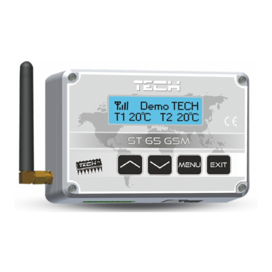
The GSM module is a device cooperating with the controllers of TECH company, allowing to remotely control the condition of the boiler operation with the use of a mobile phone. The User (via module ST-65) shall be notified with an SMS message on every boiler controller alarm. Additionally, by sending an appropriate SMS message at any time, the user receives a return message with the information on the current temperature of all sensors. -
Page 4: Description, Menu Scheme
ST-65 module GSM v1.0.7 III. DESCRIPTION, MENU SCHEME ST-65 MENU VIEW ENTERING THE MENU, ANTENNA CONFIRMING THE SETTINGS EXIT, CANCELLING SETTINGS PLUS fitting MINUS fitting VOLTAGE OUTPUT! POWER SUPPLY 9V/DC INPUT TWO SENSOR PLUG FOR COMMUNICATION WITH THE CONTROLLER CONTACT... -
Page 5: Sim Card
LANGUAGE IV. SIM CARD Module ST-65 GSM will not operate without a correctly inserted and configured SIM card. In the case when the module detects no sim card, it will switch to standby mode, waiting for a card to be inserted. The SIM card may be inserted ONLY at the time when the controller screen displays the text: "Insert the card... -
Page 6: Collecting Data From The Controller
NOTE!!! Replacement of the sim card in a different manner may result in damaging the module!!! V. COLLECTING DATA FROM THE CONTROLLER Module ST-65 GSM may work independently or with a controller by TECH company, equipped with RS communication and handling the external module. - Page 7 The SMS is sent to any authorized phone number. After sending to the module phone number the text "tech" or an authorization pin, data with controller working parameters will be sent back.
-
Page 8: Contact And Temperature Sensors
ST-65 module GSM v1.0.7 VI. CONTACT AND TEMPERATURE SENSORS Module ST-65 has 2 additional sensor connectors, one contact and one controlled output, operating independently from the boiler controller, with a universal application: 1) Two connectors intended for connection of temperature sensors (KTY) marked as T1, T2 (option –... -
Page 9: Data Collection And Settings
Working parameters of sensors and sensor connectors are set in module ST-65 by using the menu: > Sensors settings > > conf. inputs > > > conf. Inputs > > > > active > > > > inactive >... -
Page 10: Activation/Deactivation Of Alert Notices
ST-65 module GSM v1.0.7 Namely: 1234 pin 9999 A message of this type will change the module authorization pin from 1234 to 9999 and will send the return sms with the current working parameters of the boiler. !!!NOTE!!! the authorization pin is intended for changing settings and working modes of the module. -
Page 11: Operation Mode
4) Output activation Each GSM controller by TECH company is equipped with one output, which is placed in the first place from the left, looking at the view on page 3. - Page 12 ST-65 module GSM v1.0.7 Namely: 9999 W1; Message of this type will activate outputs "W" in continuous operation mode. In order to activate output "W" in time-limited mode, send a message in the format: [pin authorization] [W] [value] [space] [duration] e.g.
-
Page 13: Change And Activation Of Emergency Numbers
The user can, at any time, change the alarm number. The change can be performed by means of an SMS message or from the menu of module ST-65 GSM. The user can, at any time, change the "authorization pin" by sending a... - Page 14 ST-65 module GSM v1.0.7 Recharging Fees for sending an sms are collected in accordance with the current price list of a given operator. It should be remembered to recharge the SIM card or to pay the subscription. Available funds on the card can be controlled after logging in on the website of the GSM network operator.
-
Page 15: Sample Installation
VIII. SAMPLE INSTALLATION Module ST-65 is connected with the boiler controller by means of a four-core cable RS232 with plugs, type RJ (phone plug). Optionally, there is a possibility to buy and connect additional elements (Relay, Contact and Temperature sensors). -
Page 16: Battery Replacement: (In The Case Of Damage Or Loss Of Utility Properties)
IX. Battery replacement: (in the case of damage or loss of utility properties) Module ST-65 GSM is equipped with a Li-ion Battery. It is accepted to replace the battery only with the one which meets the below specification. Incorrect inserting of the battery can cause damage to the battery or device. - Page 17 In order to develop and improve the product, please send any comments concerning program errors or abnormal controller operation states directly to the address: SERWIS TECH: serwis@techsterowniki.pl – phone no. (+48 33) 8759380. - 17 -...
- Page 18 ST-65 module GSM v1.0.7 - 18 -...
-
Page 19: Table Of Contents
Contents I. SAFETY...............................3 II. APPLICATION............................3 III. DESCRIPTION, MENU SCHEME......................4 IV. SIM CARD..............................5 V. COLLECTING DATA FROM THE CONTROLLER................6 VI. CONTACT AND TEMPERATURE SENSORS..................8 VII. DATA COLLECTION AND SETTINGS....................9 1) Pin authorization:............................9 2) Activation/deactivation of alert notices:....................10 3) Operation mode:...........................11 4) Output activation..........................11... - Page 20 - 20 -...


Need help?
Do you have a question about the ST-65 and is the answer not in the manual?
Questions and answers