Table of Contents
Advertisement
Quick Links
Advertisement
Table of Contents

Related Manuals for Baker Hughes 525 Series


Summary of Contents for Baker Hughes 525 Series
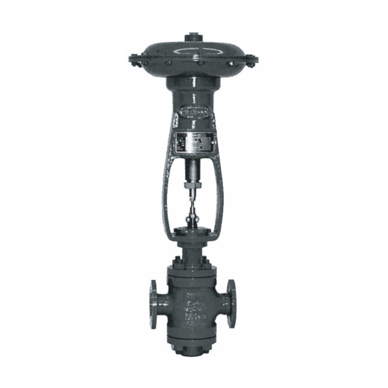
- Page 1 525 & 526 Series Reducing and Back Pressure Regulators Instruction Manual (Rev.E)
- Page 2 OPERATOR ARE STRICTLY LIMITED TO THOSE EXPRESSLY PROVIDED IN THE CONTRACT RELATING TO THE SUPPLY OF THE EQUIPMENT. NO ADDITIONAL REPRESENTATIONS OR WARRANTIES BY BAKER HUGHES REGARDING THE EQUIPMENT OR ITS USE ARE GIVEN OR IMPLIED BY THE ISSUE OF THESE INSTRUCTIONS.
-
Page 3: Table Of Contents
7.4 Pinning ..........................5 7.5 Packing Box ........................5 ................6 8. Valve Body Reassembly .......................6 8.1 525 (Reducing Service)....................6 8.2 526 (Back Pressure Service) ...................7 9. Actuators ..........................7 ......................7 Assembly Torque Requirements ....................8 Parts References ........................9 Copyright 2021 Baker Hughes Company. All rights reserved. -
Page 4: Safety Information
Warranty Baker Hughes recommended usages. Baker Hughes reserves Note: Prior to installation: • • • • Note: Indicates important facts and conditions. Copyright 2021 Baker Hughes Company. All rights reserved. -
Page 5: Introduction
1. Introduction 2. General process applications. Serial Plate After Sales Service contact the local Baker Hughes Masoneilan representative or 3. Unpacking Spare Parts through local Masoneilan representatives or Masoneilan Parts Department. Actuator and Accessories Other Options Body Series Plug Type 5. -
Page 6: Installation
6.1 525 (Reducing Service) Figure 2. Note: Spiral wound body gaskets (22) are standard in the 500 Series design and it is imperative that a new gasket be installed each time the valve is disassembled. Copyright 2021 Baker Hughes Company. All rights reserved. -
Page 7: Maintenance & Repair
Note: A sealant compatible with the process should be Note: A sealant compatible with the process should be applied sparingly to the seat ring threads and sealing applied sparingly to the seat ring threads and sealing shoulder. shoulder. Copyright 2021 Baker Hughes Company. All rights reserved. -
Page 8: Pinning
Note: While pinning is being performed, care must be taken Note: These parts may be secured using tape or wire to keep them out of the way before proceeding. Copyright 2021 Baker Hughes Company. All rights reserved. -
Page 9: Valve Body Reassembly
Note: Valve should be lapped before final assembly. See Section 7.3. Tighten nuts (10) until metal to metal contact is obtained with proper bolt torque. Refer to Table 1 for tions. Copyright 2021 Baker Hughes Company. All rights reserved. -
Page 10: 526 (Back Pressure Service)
Figure 1b: Typical Back Pressure Application Do not over tighten (See Section “7.5. Packing Box”). 9. Actuators 9.1 Type 10900 Actuators Figure 2: Lubricator Connection (Optional) Lock nut Figure 3: Seat Lapping Device Copyright 2021 Baker Hughes Company. All rights reserved. -
Page 11: Assembly Torque Requirements
1½ Stem. Hole Dia. “A” “B” “X” Dia. inches 4,78 31,75 12,7 5,56 1,562 39,67 15,7 6,35 1,875 47,63 19,1 7,92 25,4 Figure 4: Bolt Pinning Dimensions Figure 5: Bolt Tightening Sequence Copyright 2021 Baker Hughes Company. All rights reserved. -
Page 12: Parts References
525 Reducing Service 526 Back Pressure Parts References Bonnet Plug Stem Locknut Plug Packing Flange Plug Stem Packing Stud Plug Pin Blind Head Packing Copyright 2021 Baker Hughes Company. All rights reserved. - Page 13 www.controlssupplychain.com | info@controlssupplychain.com...
- Page 14 Notes Copyright 2021 Baker Hughes Company. All rights reserved.
- Page 15 Find the nearest local Channel Partner in your area: Tech Field Support & Warranty: valves.bakerhughes.com bakerhughes.com...
Need help?
Do you have a question about the 525 Series and is the answer not in the manual?
Questions and answers