
Related Manuals for Baker Hughes Mooney Flowgrid


Summary of Contents for Baker Hughes Mooney Flowgrid
- Page 1 Mooney ™ Flowgrid Regulator ™ Instruction Manual (Rev.E) Baker Hughes Data Classification : Public...
- Page 2 OPERATOR ARE STRICTLY LIMITED TO THOSE EXPRESSLY PROVIDED IN THE CONTRACT RELATING TO THE SUPPLY OF THE EQUIPMENT. NO ADDITIONAL REPRESENTATIONS OR WARRANTIES BY BAKER HUGHES REGARDING THE EQUIPMENT OR ITS USE ARE GIVEN OR IMPLIED BY THE ISSUE OF THESE INSTRUCTIONS.
-
Page 3: Table Of Contents
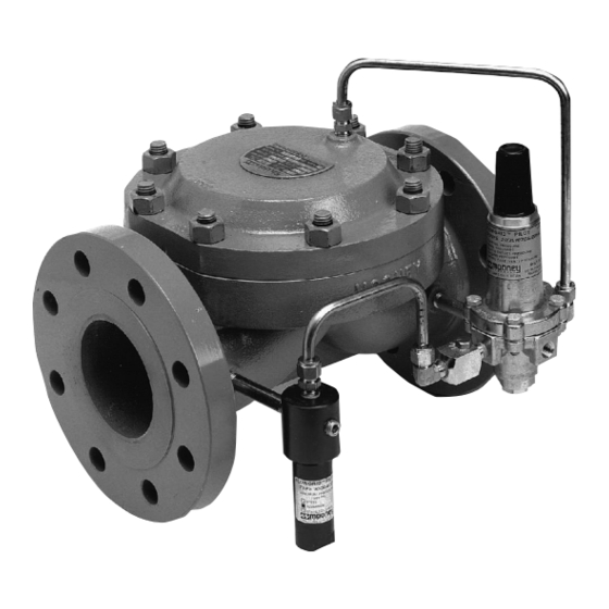
Product Description ensuring the safety and quality of the Mooney regulator. The Mooney Flowgrid regulator is an easy to maintain regulator designed to be used primarily with a self contained pilot system. The Flowgrid regulator has several unique features that add to its versatility such as: •... - Page 4 It is designed to provide stability, rangeability, and fast response All Mooney Flowgrid regulators have six main parts (excluding bolting and O-rings); the body, throttle plate, spacer, diaphragm, without stretching. It will not “take a set” and is thick for durability main spring, and spring case.
-
Page 5: Regulator Markings
Diff Min/Max differential (psig)/(bar) Max Temp Maximum operating temperature in degrees Fahrenheit Bolt Torq Recommended bolt torque for Ft-lbs/Nm spring case in foot pounds Table 3 Mooney Flowgrid Regulator Instruction Manual | 3 Copyright 2021 Baker Hughes Company. All rights reserved. -
Page 6: Principles Of Operation
Connection Connection Pilot Outlet Pilot Outlet Connection Connection Inlet Inlet Outlet Outlet Figure 6 - Back Pressure Configuration Fully Closed Figure 7 - Back Pressure Configuration Partially Open 4 | Baker Hughes Copyright 2021 Baker Hughes Company. All rights reserved. -
Page 7: Hydrostatic Testing
Inlet connection on regulator body joined to “Tee”. “Tee” connected to loading connection on spring case. C. Outlet of “Tee” connected to outlet connection on regulator Mooney Flowgrid Regulator Instruction Manual | 5 Copyright 2021 Baker Hughes Company. All rights reserved. -
Page 8: Installation
Lifting: Recommended lifting points are provided with each death, or property damage. Pilot spring cases and Mooney Flowgrid regulator. A lifting bracket is included on the regulator enclosure should be vented to a safe the spring case of the 1-2” regulators and two eye nuts on the area away from air intakes, or any hazardous loca- 3-6”... - Page 9 10 for interstage piping and sense line connection Flow recommendations. The Flowgrid Series 20 Pilot has a static sense line. Table 5 - Outlet Pressure Mooney Flowgrid Regulator Instruction Manual | 7 Copyright 2021 Baker Hughes Company. All rights reserved.
-
Page 10: Piping Details
Sense line connecting Sense port on Series 20 Pilot to upstream (BPV) or downstream (PRV) piping. Outlet port of Series 20 Pilot connected to Outlet connection of Flowgrid regulator. Pilot cartridge in PRV mode (pressure reducing) BPV (back pressure/relief) mode. 8 | Baker Hughes Copyright 2021 Baker Hughes Company. All rights reserved. - Page 11 Note: Dual port regulators in 1” - 8” sizes have been Loading Port of Series 20 Pilot connected to Loading discontinued. Schematics for reference only. connection on Spring Case (Port #1) of Flowgrid Regulator. Mooney Flowgrid Regulator Instruction Manual | 9 Copyright 2021 Baker Hughes Company. All rights reserved.
- Page 12 13. Outlet port of Series 20 Pilot connected to Outlet connection 6A. Outlet port of Series 20 Pilot connected to downstream of Flowgrid regulator. piping. 14. Pilot cartridge in PRV mode. 10 | Baker Hughes Copyright 2021 Baker Hughes Company. All rights reserved.
- Page 13 Note: In a working Monitor system with less than 25 psig (1.72 bar) differential across the second stage regulator the pilot supply (11) may be connected to the piping upstream of the first stage regulator. This will improve the shutoff of the second stage regulator. Mooney Flowgrid Regulator Instruction Manual | 11 Copyright 2021 Baker Hughes Company. All rights reserved.
-
Page 14: Start-Up And Operation
Slowly increase the pilot spring setting until the desired downstream pressure is achieved. Slowly close the downstream block regulator or vent to check the Flowgrid regulator for lockup (shut off). 12 | Baker Hughes Copyright 2021 Baker Hughes Company. All rights reserved. - Page 15 Increase the pilot spring setting of the Monitor Regulator station capacity. This applies to the Series 20 Pilot only; until the desired monitor override setting is reached. Lock in consult with Baker Hughes for applicability to other pilot setting. manufacturer’s pilots.
- Page 16 Note: In a working Monitor system with less than 25 psig (1.72 bar) differential across the second stage regulator the pilot supply may be connected to the piping upstream of the first stage regulator. This will improve the shutoff of the second stage regulator. 14 | Baker Hughes Copyright 2021 Baker Hughes Company. All rights reserved.
-
Page 17: Maintenance
The mating surface of adjacent parts must also be Reconnect the pilot system. Follow Start up procedures smooth to prevent leakage. when returning to operation. Mooney Flowgrid Regulator Instruction Manual | 15 Copyright 2021 Baker Hughes Company. All rights reserved. -
Page 18: Troubleshooting
Check to make sure needle regulators are not used on any pilot system connections. Full opening type regulators are recommended. Check for pilot vent port blockage. 16 | Baker Hughes Copyright 2021 Baker Hughes Company. All rights reserved. - Page 19 Notes Mooney Flowgrid Regulator Instruction Manual | 17 Copyright 2021 Baker Hughes Company. All rights reserved.
- Page 20 Copyright 2021 Baker Hughes Company. All rights reserved. Baker Hughes provides this information on an “as is” basis for general information purposes. Baker Hughes does not make any representation as to the accuracy or completeness of the information and makes no warranties of any kind, specific, implied or oral, to the fullest extent permissible by law, including those of merchantability and fitness for a particular purpose or use.
Need help?
Do you have a question about the Mooney Flowgrid and is the answer not in the manual?
Questions and answers