Table of Contents
Advertisement
Quick Links
Advertisement
Table of Contents

Related Manuals for Anschutz NautoPilot 5000 NX Series


Summary of Contents for Anschutz NautoPilot 5000 NX Series
- Page 1 Anschütz GmbH Zeyestr. 16-24 24106 Kiel Germany www.anschuetz.com NautoPilot® 5000 NX Series Software Version E00.01 and higher Operator Manual NautoPilot® 5100 NX NautoPilot® 5300 NX NautoPilot® 5400 NX Operator Unit 102-890.NG010 Remote Operator Unit 102-890.NG011 Edition: 002 10000001399...
- Page 2 Copyright Dieses Dokument sowie dessen Inhalt sind urheberrechtlich This document and its content are copyright protected. Distribution, geschützt. Die Weitergabe,Vervielfältigung und Speicherung sowie reproduction and storage as well as translation and exploitation of die Übersetzung wie auch Verwendung dieses Dokuments oder this document and its content, in whole or in parts and regardless of dessen Inhalts, als Ganzes oder in Teilen und egal in welcher Form what form, are prohibited without prior express written permission.
-
Page 3: Table Of Contents
NautoPilot 5000 NX Series ® Table of Contents Table of Contents List of Figures..............................V List of Tables..............................VII List of Abbreviations............................IX Introduction................................ 1 Preliminary Remarks............................. 1 Change History.............................. 1 Safety................................1 General Safety Regulations........................2 General Safety Instructions........................3 Electrostatic Discharge.......................... - Page 4 NautoPilot 5000 NX Series ® Table of Contents 1.9.3 Course Control..........................26 1.9.4 Nav Control............................ 27 1.9.5 Track Control..........................28 1.9.6 Position Monitoring........................29 1.9.7 Economy / Precision Mode (Weather Adaptivity)................29 1.9.8 Limits.............................. 30 1.9.8.1 Rudder Limit..........................30 1.9.8.2 Heading Monitor........................30 1.9.8.3 Off Heading........................... 30 1.9.8.4 Course Trim.......................... 30 1.9.8.5 Cross Track Distance Limit....................31 1.9.8.6 Track Limit Autopilot......................
- Page 5 NautoPilot 5000 NX Series ® Table of Contents 2.5.7.2 Edit Parameters........................51 2.5.7.3 Edit Set Values via Numeric Pad..................51 2.5.7.4 Edit Set Values via Drop-Down Menu..................52 2.5.8 Dead Reckoning Setup........................53 2.5.8.1 Edit Dead Reckoning Setup....................53 2.5.9 Economy / Precision Mode......................53 2.5.9.1 Select Economy / Precision Mode..................54 2.5.10 Page Selection..........................54 2.5.10.1 Open Ship Data........................
- Page 6 NautoPilot 5000 NX Series ® Table of Contents 5.5.2.3 Start Display Test......................... 68 6 Annex................................70 6.1 Alerts and Warnings..........................70 6.1.1 Alert List............................70 6.1.1.1 APIF NX Alerts........................70 6.1.1.2 Heading Control Alerts......................73 6.1.1.3 Track Control Alerts......................78 6.1.1.4 Course Control Alerts......................84 10000001399 Edition: 002...
-
Page 7: List Of Figures
NautoPilot 5000 NX Series ® List of Figures List of Figures Fig. 1: Electrostatic Discharge, Protected Area..................... 3 Fig. 2: NautoPilot 5000 NX Series, Operating Elements and Indicators............11 ® Fig. 3: Display Organization, Split Screen......................14 Fig. 4: Display Organization, 2:1 Screen......................15 Fig. - Page 8 NautoPilot 5000 NX Series ® List of Figures 10000001399 Edition: 002...
-
Page 9: List Of Tables
NautoPilot 5000 NX Series ® List of Tables List of Tables Tab. 1: Change History............................1 Tab. 2: Test Standards............................4 Tab. 3: List of Further Documents......................... 4 Tab. 4: NautoPilot 5000 NX Operator Unit, Indicator Lights (LEDs)..............12 ® Tab. 5: Operation Mode, Active / Standby LED....................12 Tab. - Page 10 NautoPilot 5000 NX Series ® List of Tables 10000001399 VIII Edition: 002...
-
Page 11: List Of Abbreviations
NautoPilot 5000 NX Series ® List of Abbreviations List of Abbreviations Acknowledged APIF Autopilot Interface Unit Advanced Steering ASIF Alarm Status Interface AS Bridge Alert Management BITE Built-In Test Equipment BNWAS Bridge Navigational Watch Alarm System Central Alert Management CAM-HMI Central Alert Management Human Machine Interface Controller Area Network CCRS... - Page 12 NautoPilot 5000 NX Series ® List of Abbreviations 10000001399 Edition: 002...
-
Page 13: Introduction
NautoPilot 5000 NX Series ® Introduction Introduction Preliminary Remarks The present manual is a description and reference book only. It is intended to answer questions and to solve problems in the quickest possible manner. Read and follow the instructions and notes in this manual before operating the equipment. For this purpose, refer to the table of contents and read the corresponding chapters thoroughly. -
Page 14: Safety
NautoPilot 5000 NX Series ® Introduction Safety General Safety Regulations The following safety symbols are used in this manual: WARNING! Warning statements indicate a hazardous situation that, if not avoided, could result in minor, moderate or serious injury, or death Consequence •... -
Page 15: General Safety Instructions
NautoPilot 5000 NX Series ® Introduction General Safety Instructions Electrostatic Discharge Fig. 1: Electrostatic Discharge, Protected Area Table Mat Ground Cord Dissipative Shoes Floor Mat Wrist Band Wrist Strap Common Ground Ground Point Any product which is labeled as shown is electrostatic sensitive. If proper precautions are not taken, handling or working on Electrostatic Discharge (ESD) -
Page 16: Test Standards
NautoPilot 5000 NX Series ® Introduction Test Standards Tab. 2: Test Standards Standards Description Maritime navigation and radiocommunication equipment and systems - Bridge alert management - Part 1: Operational and IEC 62923-1 performance requirements, methods of testing and required test results Maritime navigation and radiocommunication equipment and systems - Integrated navigation systems - Part 2: Modular... - Page 17 NautoPilot 5000 NX Series ® Introduction Documentation No. Designation 10000001271 Rudder Feedback Unit AS Operator and Service Manual 10000001560 Autopilot NX Interface Unit Service Manual 10000001266 CAN Bus Distribution Unit AS Operator and Service Manual Edition: 002 10000001399...
-
Page 18: Description
NautoPilot 5000 NX Series ® 1 Description 1 Description 1.1 Preliminary Remarks 1.2 Purpose The NautoPilot 5000 NX Series is part of the steering system family AS (Advanced ® Steering) and is used to control heading at sea for all sizes of seagoing vessels. It was designed for the use in normal and high-speed vessels. - Page 19 NautoPilot 5000 NX Series ® 1 Description Inputs (Status) Status (plugs B10, B11) 24 V DC, max. 5 mA Outputs / Inputs Serial in / out (plugs B8, B9) RS422 (NMEA*) CAN bus (plugs B21, B22) according to Anschütz CAN bus specifica- tion Ethernet Signal Inputs...
- Page 20 NautoPilot 5000 NX Series ® 1 Description PANZALQ Acknowledgement for Alarms, Messages, Warnings PANZALR Request for Alarms, Messages, Cautions PANZCRQ Command / Request PANZEST ECDIS Status PANZPSR Set Radius, Set ROT PANZXTD Cross Track Distance Recommended Minimum Specific GNSS Data True Heading and Status Dual Ground/Water Speed Water Speed and Heading Course over Ground and Ground Speed...
-
Page 21: Technical Description
NautoPilot 5000 NX Series ® 1 Description PANZRSI Rudder Position PANZSSR Preset Radius, Preset ROT and Set Heading Full Turn PANZSTA Status Autopilot Rudder Sensor Angle System Function ID Resolution Protocol True Heading and Status Text Transmission Version Water Speed and Heading ** according to IEC 61162-1 1.5 ... -
Page 22: Nautopilot® 5400 Nx
NautoPilot 5000 NX Series ® 1 Description 1.5.3 NautoPilot® 5400 NX Automatically adaption to weather and sea state using a rudder variance control. Toe angle control for dual rudder vessels to improve fuel efficiency. Increased performance by adjusting ECONOMY / PRECISION mode: •... -
Page 23: Operating Elements And Indications
NautoPilot 5000 NX Series ® 1 Description 1.6 Operating Elements and Indications Fig. 2: NautoPilot® 5000 NX Series, Operating Elements and Indicators Pos. Area / Element Description Touchscreen display Shows data and enables operation via softkeys Acknowledges an alert or status message LED flashing indicates the first occurrence of an alert or status message LED constantly light up indicates an acknowledged... -
Page 24: Tab. 4: Nautopilot® 5000 Nx Operator Unit, Indicator Lights (Leds)
NautoPilot 5000 NX Series ® 1 Description Pos. Area / Element Description Activates user interface Pushbutton Active / Standby with 2 LEDs Activates heading control mode Turn: • Adjusts set heading within HDG CTRL • Adjusts the set course in CRS CTRL Rotary knob Press: •... - Page 25 NautoPilot 5000 NX Series ® 1 Description Color Description System buzzer is disabled Alert buzzer is disabled Ethernet 1 is connected Yellow Green Ethernet 1 is connected Green flashing Data transmission at Ethernet 1 Ethernet 2 is connected Yellow Green Ethernet 2 is connected Green flashing Data transmission at Ethernet 2 Alert is processed and transferred via relay SYS...
-
Page 26: Display Organization
NautoPilot 5000 NX Series ® 1 Description 1.7 Display Organization Fig. 3: Display Organization, Split Screen Page Information Bar Central Area Control Mode Selection Page Selection Settings Area Information Area 10000001399 Edition: 002... -
Page 27: Information Bar
NautoPilot 5000 NX Series ® 1 Description Fig. 4: Display Organization, 2:1 Screen Page Information Bar Central Area Control Mode Selection Page Selection 1.7.1 Information Bar The information bar shows display and parameter set information. The shown values are for information only and cannot be edited. Alert messages are also shown in the information bar. -
Page 28: Page Selection
NautoPilot 5000 NX Series ® 1 Description Area / Element Description Softkey HDG CTRL Selects Heading Control mode Softkey CRS CTRL Selects Course Control mode Softkey NAV CTRL Selects Nav Control mode 1.7.4 Page Selection This area is used to open further pages. The display and its content may vary according to the selected page. -
Page 29: Display Pages
NautoPilot 5000 NX Series ® 1 Description Information Area, LIMITS Area / Element Description Information field RUD Shows set rudder limit in degrees Information field OFF Shows set off heading limit in degrees Information field HDG Shows set heading monitoring limit in degrees Information field XTD Shows cross track distance limit in meters Information Area, SPEED... -
Page 30: Heading Control
NautoPilot 5000 NX Series ® 1 Description Fig. 5: Page: Standby Area / Element Description CENTRAL AREA Information field HDG Shows actual heading in degrees and data source Shows difference between actual heading and set heading in Scale HDG DIFF increments of x degrees Entry field SET HDG Shows value for set heading in degrees Shows value for set rate of turn in degrees per minute... -
Page 31: Simplified View
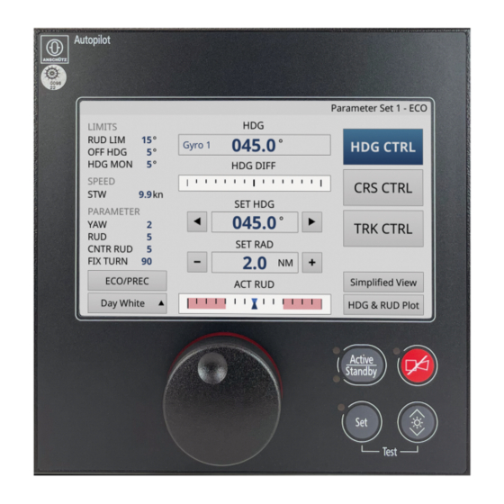
NautoPilot 5000 NX Series ® 1 Description Fig. 6: Page: Heading Control, Main Area / Element Description CENTRAL AREA Information field HDG Shows actual heading in degrees and data source Shows difference between actual heading and set heading in Scale HDG DIFF increments of x degrees Shows value for preset heading value in degrees Information and entry... -
Page 32: Course Control
NautoPilot 5000 NX Series ® 1 Description Fig. 7: Page: Simplified View Area / Element Description CENTRAL AREA Information field HDG Shows actual heading in degrees and data source Shows value for set heading in degrees Entry field SET HDG Softkeys arrow left or arrow right add / deduct the set value for FIX TURN to the set heading Information field ACT Shows actual rudder position in degrees for port rudder... -
Page 33: Nav Control
NautoPilot 5000 NX Series ® 1 Description Fig. 8: Page: Course Control, Main Area / Element Description CENTRAL AREA Shows actual heading in degrees and data source Scale XTD Shows cross track distance in increments of x meters Information and entry Shows value for set course in degrees field SET CRS Shows value for set rate of turn in degrees per minute... -
Page 34: Position Monitor
NautoPilot 5000 NX Series ® 1 Description Fig. 9: Page: Nav Control, Main Area / Element Description CENTRAL AREA Information field HDG Shows actual heading in degrees and data source Scale XTD Shows cross track distance in increments of x meters Information and entry Shows value for set course in degrees field SET CRS... -
Page 35: Fig. 10: Page: Position Monitor
NautoPilot 5000 NX Series ® 1 Description Fig. 10: Page: Position Monitor Area / Element Description Shows name and information of page Page Information Bar If related alerts are active, the alert information overwrites the page information Information Area Information field HDG Shows actual heading in degrees and data source Entry field SET CRS Shows value for set course in degrees... -
Page 36: Track Data
NautoPilot 5000 NX Series ® 1 Description 1.8.7 Track Data Note Only available in course and nav control mode. Editable values can be adjusted by selecting the respective field. Fig. 11: Page: Track Data Area / Element Description Information Area Information field HDG Shows actual heading in degrees and data source Entry field SET CRS Shows value for set course in degrees... -
Page 37: Functional Description
NautoPilot 5000 NX Series ® 1 Description Fig. 12: Page: HDG & RUD Plot Area / Element Description Central Area Time axis for time recorded in minutes Left scale with round checkbox in top left cor- Round checkbox to switch axis resolution between 5 minutes and 20 minutes Heading axis for heading recorded in degrees Top scale with round... -
Page 38: Heading Control
NautoPilot 5000 NX Series ® 1 Description 1.9.2 Heading Control Heading control requires actual heading from a gyro compass, a magnetic compass or a transmitting heading device. Fig. 13: Principle of Heading Control The autopilot controls the heading by comparing the set heading value and the actual heading value. -
Page 39: Nav Control
NautoPilot 5000 NX Series ® 1 Description Fig. 15: Comparison of Heading Control and Course Control 1.9.4 Nav Control Note Nav control is available for types NautoPilot 5100 NX and NautoPilot 5300 NX. ® ® In nav control mode the route - consisting of 2 or more waypoints - is planned on a GPS, chart plotter or equivalent navigation system. -
Page 40: Track Control
NautoPilot 5000 NX Series ® 1 Description Note The nav control mode may only be used on non-SOLAS vessels. It must not be used on vessels following SOLAS regulation. SOLAS CONSOLIDATED EDITION 2009, Chapter I, Regulation 3, Part 1 describes the following exceptions for non-SOLAS vessels: (a) The present regulations, unless expressly provided otherwise, do not apply to: •... -
Page 41: Position Monitoring
NautoPilot 5000 NX Series ® 1 Description Area / Element Description FROM-WPT Previous waypoint NEXT-WPT Waypoint following to TO-WPT Wheel Over Line (WOL). The line of the track where the planned track change maneuver is intended to start. Approach time is the time before the when the approach message is indicated on the NautoPilot 5000 NX Operator Unit. -
Page 42: Limits
NautoPilot 5000 NX Series ® 1 Description 1.9.8 Limits Limits are set to limit values and to generate an alert if a certain value is exceeded. 1.9.8.1 Rudder Limit The rudder limit is set according to the maximum / physical rudder limit and sets limits for command rudder output of the autopilot. -
Page 43: Cross Track Distance Limit
NautoPilot 5000 NX Series ® 1 Description Fig. 17: Principle of Course Trim Angle Course and heading may have different values, caused by drift, wind or sea state. The course trim angle can only be adjusted for course control, nav control and track control modes. -
Page 44: Rudder
NautoPilot 5000 NX Series ® 1 Description The yawing setting determines rudder activity and heading accuracy for the autopilot‘s control properties. The possible range is 1 to 6 (in increments of 1). Default value is 2. Value Description Recommended for Signifies control with the greatest amount of activity Calm sea (maximum accuracy level) Signifies control with the lowest amount of activity... -
Page 45: Step Width
NautoPilot 5000 NX Series ® 1 Description Value Description Possible Result Small counter rudder The ship overshoots the selected heading movement High counter rudder The ship reaches the new set heading too slowly movement If the rudder movement in counter direction at the end of a heading change is too strong or comes too early resulting in too slow setting to the new set heading value, counter rudder should be decreased. -
Page 46: Ship Load
NautoPilot 5000 NX Series ® 1 Description 1.9.9.7 Ship Load Each ship has a typical behavior depending on the load of a ship. This parameter considers the ship’s load for the steering control by an autopilot. This parameter is set according to the load percentage. 10 % is for the lowest load condition. -
Page 47: Bridge Alert Management
NautoPilot 5000 NX Series ® 1 Description Out- Plug put / Assignment Data / Signal Input X505 Out / in RS422 serial input / output Sensor data, navigation data, alert X506 Out / in RS422 serial input / output data X507 Out / in RS422 serial input / output Indicates a failure within the NautoPi- 5000 NX Operator Unit if neces-... -
Page 48: Tab. 6: Alert List, Alarm Symbols
NautoPilot 5000 NX Series ® 1 Description On the bridge alerts are presented on the individual equipment and/or on a Central Alert Management Human Machine Interface (CAM-HMI). Alerts are divided in different priorities: • Emergency alarm Highest priority of an alert. These alarms show immediate danger to human life or to the ship and its machinery and demand immediate action. -
Page 49: Tab. 7: Alert List, Warning Symbols
NautoPilot 5000 NX Series ® 1 Description Symbol Description Rectified – unacknowledged alarm (flashing) Active – responsibility transferred alarm Tab. 7: Alert List, Warning Symbols Symbol Description Active – unacknowledged warning (flashing) Active – silenced warning (flashing) Active – acknowledged warning Rectified –... -
Page 50: Outfit And Accessories
NautoPilot 5000 NX Series ® 1 Description Tab. 10: Acknowledge not Allowed Symbols Symbol Description Emergency alarm – acknowledge not allowed Alarm – acknowledge not allowed Warning – acknowledge not allowed 1.14 Outfit and Accessories This system or equipment comprises no outfit or accessories. 10000001399 Edition: 002... -
Page 51: Operation
NautoPilot 5000 NX Series ® 2 Operation 2 Operation 2.1 Preliminary Remarks User Rights The manual is a complete documentation of the system or equipment. Some functions may not be accessible depending on user rights. All functions or operations are described irrespective of the actual user rights of the user. Markup Elements The manual uses different markup elements for hardware and software. -
Page 52: Setting Into Operation
NautoPilot 5000 NX Series ® 2 Operation 2.3 Safety Instructions for Autopilot Operation WARNING! Danger due to dangerous situations while using the autopilot Risk of collisions or grounding causing serious injury and material damage • Check the traffic at sea and the sea area in front while using any control function of the autopilot. -
Page 53: Normal Operation
NautoPilot 5000 NX Series ® 2 Operation 2.5 Normal Operation 2.5.1 General Information 2.5.1.1 General Touchscreen Indications and Handling The software provides some general features which apply for several tasks. Softkeys with Delay Function Some softkeys are provided with a defined timeout to avoid unintentional activation. If a softkey with delay function is selected, a progress bar appears under the softkey. -
Page 54: Fig. 20: Disabled Element, Example
NautoPilot 5000 NX Series ® 2 Operation Fig. 20: Disabled Element, Example Sort Function in Lists Some lists are sortable. Fig. 21: Sort Criterion Indicator The arrow above the selected column header marks it as sort criterion and shows the actual sort order. General Handling Elements Tab. -
Page 55: Fig. 22: On-Screen Keyboard
NautoPilot 5000 NX Series ® 2 Operation Symbol Area / Element Description Softkey Menu Selec- Switches back to the menu selection tion Symbol Set Setting can be confirmed via pushbutton Set Input Options Specific input dialogs and elements simplify the input or adjustment of values. These are: •... -
Page 56: Activate Autopilot
NautoPilot 5000 NX Series ® 2 Operation A new value is shown in italic characters until it is confirmed. Sensor Data Status Indicator If the data quality / status of a sensor is not sufficient for a function, it is indicated by a colored bar beside the respective field. -
Page 57: Change Color Mode
NautoPilot 5000 NX Series ® 2 Operation 2.5.3.1 Change Color Mode Procedure 1. Select a color mode via the drop-down menu at the bottom left corner of the display page. ► The color mode changes. 2.5.3.2 Adjust Dimming Procedure 1. Press and hold the pushbutton Dim. ►... -
Page 58: Select Course Control Mode
NautoPilot 5000 NX Series ® 2 Operation Procedure 1. Select and hold the softkey HDG CTRL as long as the green time bar is shown. ► A blue time bar is shown during the mode change. ► Main heading control display page opens, see chapter 1.8.2. -
Page 59: Limit Settings
NautoPilot 5000 NX Series ® 2 Operation ► All available settings and values are shown. ► Nav control mode is activated. 2.5.5 Limit Settings The NautoPilot 5000 NX Series provides a variety of settings for the control modes. ® The set limits are shown in the information area of the display, see chapter 1.7.6. -
Page 60: Speed Setting
NautoPilot 5000 NX Series ® 2 Operation ► The selected item is marked with a frame. 3. Delete the current value and set a new value. 4. Select the softkey Confirm Dialog to confirm. ► The new value is set. ► The dialog closes. 2.5.6 ... -
Page 61: Parameter Settings
NautoPilot 5000 NX Series ® 2 Operation Fig. 24: Dialog: Speed Selection 2. Select the speed option. ► If Manual Speed Input is selected, a numeric pad opens. ► The selected item is marked with a frame. 3. Delete the current value and set a new value. 4. -
Page 62: Select Parameter Set
NautoPilot 5000 NX Series ® 2 Operation For Adjustment, Setting Possible Range 1 (maximum accuracy level) to 6 (minimum Yawing accuracy level) in increments of 1, default is chapter 2.5.7.2 1 (weak rudder movement) to 9 (strong rud- Rudder der movement) in increments of 1, default is chapter 2.5.7.2 0 (small movement) to 9 (high movement) in Counter Rudder... -
Page 63: Edit Parameters
NautoPilot 5000 NX Series ® 2 Operation 2.5.7.2 Edit Parameters Procedure 1. Select a parameter set, see chapter 2.5.7.1. 2. Select the softkey Edit. ► The dialog Edit Parameter Set x opens. 3. Select the value to be edited. ► The selected item is marked with a frame. ►... -
Page 64: Edit Set Values Via Drop-Down Menu
NautoPilot 5000 NX Series ® 2 Operation ► The selected item is marked with a frame. 3. Delete the current value and set a new value. 4. Select the softkey Confirm Dialog to confirm. ► The new value is set. ► The dialog closes. 2.5.7.4 ... -
Page 65: Dead Reckoning Setup
NautoPilot 5000 NX Series ® 2 Operation ► The dialog closes. 2.5.8 Dead Reckoning Setup is calculated using drift speed in knots and drift direction in degrees. Dead Reckoning (DR) It can be used as a secondary sensor source for position monitoring. 2.5.8.1 ... -
Page 66: Select Economy / Precision Mode
NautoPilot 5000 NX Series ® 2 Operation 2.5.9.1 Select Economy / Precision Mode Procedure Note Economy / precision mode is available for types NautoPilot 5300 NX and NautoPilot ® ® 5400 NX. 1. Select the softkey ECO/PREC to switch between economy and precision mode. ►... -
Page 67: Open About Page (Copyright Information)
NautoPilot 5000 NX Series ® 2 Operation 2.5.10.2 Open About Page (Copyright Information) Procedure Note Only available in standby mode. 1. Open page Ship Data, see chapter 2.5.10.1. 2. Select the softkey About. ► The page About opens. Fig. 27: Page: About 3. -
Page 68: Open Position Monitor
NautoPilot 5000 NX Series ® 2 Operation 2.5.10.5 Open Position Monitor Procedure Note Position Monitor is available in course control and nav control mode. 1. Select the softkey POS MON. ► The page POS MON opens. 2. Select the softkey Main to return to the main nav control display page. 2.5.10.6 ... -
Page 69: Set Heading
NautoPilot 5000 NX Series ® 2 Operation Fig. 28: Dialog: HDG Selection 2. Select a heading data source. 3. Select the pushbutton Set to confirm. ► The dialog closes. 2.5.11.2 Set Heading Procedure Note Only available in heading control mode. 1. Make a choice out of the following options: a) Turn the rotary knob to edit the value and press pushbutton Set to confirm. -
Page 70: Set Heading Via Fix Turn
NautoPilot 5000 NX Series ® 2 Operation 2.5.11.3 Set Heading via Fix Turn Procedure Note Only available in heading control mode. 1. Make a choice out of the following options: a) Select the softkey Arrow Left to change the set heading to port. b) Select the softkey Arrow Right to change the set heading to starboard. -
Page 71: Select Set Rot Or Set Rad For Display
NautoPilot 5000 NX Series ® 2 Operation 2.5.11.5 Select SET ROT or SET RAD for display Procedure 1. Select the information field SET ROT or SET RAD. ► The dialog Rate Of Turn & Radius opens. Fig. 29: Dialog: Rate Of Turn & Radius 2. -
Page 72: Set Radius Directly
NautoPilot 5000 NX Series ® 2 Operation ► LED at pushbutton Set is flashing. 4. Select the softkey Confirm Dialog within the numeric pad or press the pushbutton Set to confirm. ► The new rate of turn is set. 2.5.11.8 Set Radius Directly Procedure 1. -
Page 73: Setting Out Of Operation
NautoPilot 5000 NX Series ® 2 Operation ► The new value for ship load percentage is set. 2.6 Setting out of Operation Procedure 1. Disconnect the supply voltage. ► The NautoPilot 5000 NX is switched off. ® Note There is no separate ON/OFF switch. Edition: 002 10000001399... -
Page 74: Alert / Status Message Handling
NautoPilot 5000 NX Series ® 3 Alert / Status Message Handling 3 Alert / Status Message Handling Note It is advisable to acknowledge each warning, caution and information message. It is strongly advisable to acknowledge each alarm and to resolve its cause before continuing with a control mode. -
Page 75: Acknowledgement Of Alert Messages
NautoPilot 5000 NX Series ® 3 Alert / Status Message Handling 3.2 Acknowledgement of Alert Messages Note It is also possible to acknowledge alerts at an inactive remote NautoPilot 5000 NX ® Operator Unit. Alarm and warning messages are acknowledged via the pushbutton ACK, see chapter 3.2.1. -
Page 76: Possible Alarms, Warning And Cautions
NautoPilot 5000 NX Series ® 3 Alert / Status Message Handling 3.5 Possible Alarms, Warning and Cautions For a list of alerts, see chapter 6.1.1. 3.6 Central / System Alarms Alarms and warnings are either transmitted to a central alarm panel as central alarm or combined as part of a system alarm. -
Page 77: Troubleshooting
NautoPilot 5000 NX Series ® 4 Troubleshooting 4 Troubleshooting 4.1 Troubleshooting Table Tab. 12: Troubleshooting Table Failure Possible Cause Remedy Operator unit does not Replace fuse, see chap- Fuse is broken start ter 5.5.2.2 Display, operating ele- ment or LED is defective Operator unit does not re- Contact Anschütz service act on input... -
Page 78: Care And Maintenance
NautoPilot 5000 NX Series ® 5 Care and Maintenance 5 Care and Maintenance Note The NautoPilot 5000 NX is an important part of the steering gear control system. ® Regarding the ship’s safety, particular attention must therefore be paid to its care and maintenance and the use of original Anschütz equipment / parts only. -
Page 79: Repair
NautoPilot 5000 NX Series ® 5 Care and Maintenance 5.5 Repair WARNING! Danger due to electrical current Risk of death or serious injury that is caused by electrical shock • Switch off voltage supply before starting work. • Secure against switching on again. •... -
Page 80: Repair Procedures
NautoPilot 5000 NX Series ® 5 Care and Maintenance 5.5.2 Repair Procedures 5.5.2.1 Perform a Reset Procedure CAUTION! Hazard due to wrong use of reset button Risk of material damage • Do not use metallic objects to push the reset button. 1. - Page 81 NautoPilot 5000 NX Series ® 5 Care and Maintenance 3. Press pushbutton Set to stop the display test at any time. ► Display shows previous display page. 4. Contact Anschütz service if any tested component failed the test. Edition: 002 10000001399...
-
Page 82: Annex
NautoPilot 5000 NX Series ® 6 Annex 6 Annex 6.1 Alerts and Warnings 6.1.1 Alert List Note Messages / alarms with the APIF NX add-on are only possible if an autopilot interface is installed (standalone application) and the NautoPilot 5000 NX Operator Unit is ®... - Page 83 NautoPilot 5000 NX Series ® 6 Annex Alert Title Priority Esca- Possible Cause Remedy lation Alert Description Category Type GYRO FAIL Caution Repeated Gyro connected to APIF NX Check Gyro connected to APIF failed APIF NX GYRO HDG FAILED: CHECK SENSOR HCS NOT AVAIL Warning Next pri-...
- Page 84 NautoPilot 5000 NX Series ® 6 Annex Alert Title Priority Esca- Possible Cause Remedy lation Alert Description Category Type RUD STOPPED Alarm Next pri- APIF NX failure or external Check APIF NX Manual, use ority rudder stop status received, manual steering APIF NX RUDDER rudder is frozen STOP: USE MAN...
-
Page 85: Heading Control Alerts
NautoPilot 5000 NX Series ® 6 Annex Alert Title Priority Esca- Possible Cause Remedy lation Alert Description Category Type SYSTEM FAIL None APIF NX hardware failure or Restart APIF NX, use manual application restart steering APIF NX SYSTEM FAILURE: USE MAN STEERING SYSTEM FAIL Warning... - Page 86 NautoPilot 5000 NX Series ® 6 Annex Alert Title Priority Esca- Possible Cause Remedy lation Alert Description Category Type HCS NOT AVAIL Warning Next pri- Unexpected behavior in case ority of giveover of rudder control by CANNOT ACTIVATE steering system HCS: USE MAN STEERING Heading control is not activat- HCS NOT AVAIL...
- Page 87 NautoPilot 5000 NX Series ® 6 Annex Alert Title Priority Esca- Possible Cause Remedy lation Alert Description Category Type HDG CHANGED Caution None Automatic change of selected heading sensor SENSOR USED FOR CONTROL FUNCTION CHANGED HDG DOUBTFUL Warning Repeated Heading monitoring impossi- ble, only magnetic sensor is HDG MON IM- available...
- Page 88 NautoPilot 5000 NX Series ® 6 Annex Alert Title Priority Esca- Possible Cause Remedy lation Alert Description Category Type LOST HDG CTRL None No heading information avail- Use manual steering, check able during heading control heading sensors NO HEADING: USE MAN STEERING Heading control remains active but rudder is frozen LOW SPEED...
- Page 89 NautoPilot 5000 NX Series ® 6 Annex Alert Title Priority Esca- Possible Cause Remedy lation Alert Description Category Type NO RUD CTRL Caution None No steering status on CAN bus Check steering system received during control NO RUDDER CTRL ON CAN: USE MAN Rudder is frozen STEERING NO SET HDG...
-
Page 90: Track Control Alerts
NautoPilot 5000 NX Series ® 6 Annex Alert Title Priority Esca- Possible Cause Remedy lation Alert Description Category Type RUDDER STOP Alarm Next pri- Rudder is stopped due to loss Check the preselected set ority of heading information during heading and acknowledge it or CHECK AND ACK heading control and no mode use manual steering... - Page 91 NautoPilot 5000 NX Series ® 6 Annex Alert Title Category Esca- Possible Cause Remedy lation Alert Description Priority Type BACKUP POSTION SENSOR CHANGED CHECK LIMITS Warning Repeated Track control was interrupted, Check and adjust limits for limits for RAD / ROT and rud- RAD / ROT and rudder limit CHECK RUD- der limit might have changed...
- Page 92 NautoPilot 5000 NX Series ® 6 Annex Alert Title Category Esca- Possible Cause Remedy lation Alert Description Priority Type NO VALID SPD Warning Repeated No speed available during tr- rack control SWITCH TO A VALID SPEED SOURCE POSN CHANGED Caution None Automatic change of position sensor used for control POSN SENSOR...
- Page 93 NautoPilot 5000 NX Series ® 6 Annex Alert Title Category Esca- Possible Cause Remedy lation Alert Description Priority Type TCS NOT AVAIL Caution None NP5400 NX: track control is NP5400 NX: Activated track only initiated by the ECDIS control at the ECDIS Other ACTIVATE TRACK Types: check configuration CONTROL ON...
- Page 94 NautoPilot 5000 NX Series ® 6 Annex Alert Title Category Esca- Possible Cause Remedy lation Alert Description Priority Type TCS STOPPED Warning Next pri- Track control interrupted, Check ECDIS ority no leg course received from NO SET CRS: ECDIS CHECK SET CRS FROM ECDIS TCS STOPPED Alarm...
- Page 95 NautoPilot 5000 NX Series ® 6 Annex Alert Title Category Esca- Possible Cause Remedy lation Alert Description Priority Type TCS STOPPED Warning Next pri- Jump in selected position data Check position sensor ority detected POSITION JUMP: CHECK POSITION TCS STOPPED Alarm Next pri- Jump in selected position data Check position sensor...
-
Page 96: Course Control Alerts
NautoPilot 5000 NX Series ® 6 Annex 6.1.1.4 Course Control Alerts Alert Title Priority Esca- Possible Cause Remedy lation Alert Description Category Type CC NOT AVAIL Caution None Autopilot type does not include Upgrade license course control function CC NOT INCLUDED: USE HDG CTRL CC NOT AVAIL Caution... - Page 97 NautoPilot 5000 NX Series ® 6 Annex Alert Title Priority Esca- Possible Cause Remedy lation Alert Description Category Type CC STOPPED None Course control interrupted, Use manual steering, check missing heading information heading sensors NO HEADING: USE MAN STEERING Heading control is activated as fallback and rudder is frozen CC STOPPED Alarm...
- Page 98 NautoPilot 5000 NX Series ® 6 Annex Alert Title Priority Esca- Possible Cause Remedy lation Alert Description Category Type CC STOPPED None Course control interrupted, a Select gyro sensor magnetic heading sensor was MAG HDG SELECT- selected ED: SELECT GYRO HEADING Heading control is activated as fallback CC STOPPED...
Need help?
Do you have a question about the NautoPilot 5000 NX Series and is the answer not in the manual?
Questions and answers