Sign In
Upload
Manuals
Brands
Anschutz Manuals
Marine Equipment
NautoPilot 5000 NX Series
Anschutz NautoPilot 5000 NX Series Manuals
Manuals and User Guides for Anschutz NautoPilot 5000 NX Series. We have
2
Anschutz NautoPilot 5000 NX Series manuals available for free PDF download: Operator's Manual
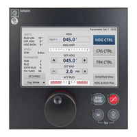
Anschutz NautoPilot 5000 NX Series Operator's Manual (104 pages)
Brand:
Anschutz
| Category:
Autopilot System
| Size: 3 MB
Table of Contents
Table of Contents
3
List of Figures
7
List of Tables
9
List of Abbreviations
11
Introduction
13
Preliminary Remarks
13
Change History
13
Tab. 1: Change History
13
Safety
14
General Safety Regulations
14
General Safety Instructions
15
Electrostatic Discharge
15
Fig. 1: Electrostatic Discharge, Protected Area
15
Standard Compliancy
16
List of Further Documents
16
Tab. 2: List of Standards
16
Tab. 3: List of Further Documents
16
Description
18
Preliminary Remarks
18
Purpose
18
Use Limitations
18
Technical Data
18
Technical Description
21
Nautopilot® 5100 NX
21
Nautopilot® 5300 NX
21
Nautopilot® 5400 NX
22
Nautopilot® 5000 NX Remote Unit
22
Stand-Alone Application
22
Integrated Application
22
Operating Elements and Indications
23
Fig. 2: Nautopilot® 5000 NX, Operating Elements and Indicators
23
Tab. 4: Nautopilot® 5000 NX Operator Unit, Indicator Lights (Leds)
24
Tab. 5: Operation Mode, Active / Standby LED
24
Display Organization
25
Fig. 3: Display Organization, Split Screen
25
Information Bar
26
Central Area
26
Control Mode Selection
26
Fig. 4: Display Organization, 2:1 Screen
26
Page Selection
27
Settings Area
27
Information Area
27
Display Pages
28
Standby
28
Heading Control
29
Fig. 5: Page: Standby
29
Simplified View
30
Fig. 6: Page: Heading Control, Main
30
Course Control
31
Fig. 7: Page: Simplified View
31
Nav Control
32
Fig. 8: Page: Course Control, Main
32
Fig. 9: Page: Nav Control, Main
33
External Heading Control
34
Fig. 10: Page: External Heading Control, Main
34
Position Monitor
35
Fig. 11: Page: Position Monitor
35
Track Data
36
Fig. 12: Page: Track Data
36
Heading & Rudder Plot
37
Fig. 13: Page: HDG & RUD Plot
37
Functional Description
38
Standby Status
38
Heading Control
38
Course Control
38
Fig. 14: Principle of Heading Control
38
Nav Control
39
Fig. 15: Principle of Course Control
39
Fig. 16: Comparison of Heading Control and Course Control
39
Track Control
40
Fig. 17: Principle of Track Control
41
External Heading Control
42
Fig. 18: External Heading Control Mode, Active
42
Position Monitoring
43
Fig. 19: External Heading Control Mode, Dialog: Limits
43
Fig. 20: External Heading Control Mode, Dialog: Rate of Turn & Radius
43
Economy / Precision Mode (Weather Adaptivity)
44
Limits
44
Rudder Limit
44
Heading Monitor
44
Off Heading
44
Course Trim
45
Cross Track Distance Limit
45
Fig. 21: Principle of Course Trim Angle
45
Track Limit Autopilot
46
Parameters
46
Yawing
46
Rudder
46
Counter Rudder
47
Step Width
47
Fix Turn
47
Toe Angle
47
Ship Load
48
Modes of Normal Operation
48
Emergency Operation
48
Dependence on Peripheral Systems / Devices
48
Interfaces / Plug Assignment
49
Bridge Alert Management
50
Tab. 6: Alert List, Alarm Symbols
51
Tab. 7: Alert List, Warning Symbols
51
Tab. 8: Alert List, Caution Symbols
51
Outfit and Accessories
52
Tab. 9: Alert Signaling
52
Tab. 10: Acknowledge Not Allowed Symbols
52
Operation
53
Preliminary Remarks
53
Safety Instructions for Operation
53
Safety Instructions for Autopilot Operation
54
Setting into Operation
54
Normal Operation
55
General Information
55
General Touchscreen Indications and Handling
55
Fig. 22: Activated Element, Example
55
Fig. 23: Deactivated Element, Example
55
Fig. 24: Indicating Elements: Inactive, Active
55
Fig. 25: Disabled Element, Example
56
Fig. 26: Sort Criterion Indicator
56
Tab. 11: General Handling Elements
56
Fig. 27: On-Screen Keyboard
57
Activate Autopilot
58
Fig. 28: Dialog: Numeric Input
58
Primary / Secondary Operator Unit Selection
59
Set Operator Unit to Active
59
Color Mode
59
Change Color Mode
60
Adjust Dimming
60
Control Mode Selection
60
Fig. 29: Drop-Down Menu: Color Mode
60
Select Heading Control Mode
61
Select Course Control Mode
61
Select Nav Control Mode
62
Limit Settings
62
Edit Limits
62
Speed Setting
63
Fig. 30: Dialog: Limits
63
Fig. 31: Dialog: Limits, Numeric Input
63
Select Speed Source
64
Edit Manual Speed
64
Fig. 32: Dialog: Speed Selection
64
Parameter Settings
65
Fig. 33: Dialog: Speed Selection, Manual Speed Input
65
Select Parameter Set
66
Edit Parameters
66
Fig. 34: Dialog: Parameter Memory
66
Edit Set Values Via Numeric Pad
67
Fig. 35: Dialog: Parameter Memory, Numeric Input
67
Fig. 36: Dialog: Set Value Settings
67
Edit Set Values Via Drop-Down Menu
68
Fig. 37: Dialog: Set Value Settings, Numeric Input
68
Dead Reckoning Setup
69
Edit Dead Reckoning Setup
69
Fig. 38: Drop-Down Menu: SET HDG Increment
69
Fig. 39: Drop-Down Menu: SET HDG Increment, Set Requested
69
Economy / Precision Mode
70
Select Economy / Precision Mode
70
Page Selection
70
Fig. 40: Dialog: Setup DR
70
Open Ship Data
71
Open about Page (Copyright Information)
71
Fig. 41: Page: Ship Data
71
Open Simplified View
72
Open HDG & RUD Plot
72
Open Position Monitor
72
Fig. 42: Page: about
72
Open Track Data
73
Main Settings
73
Select Heading Source
73
Fig. 43: Dialog: HDG Selection
73
Set Heading
74
Set Heading Via Fix Turn
74
Set Scale of HDG & RUD Plot
75
Set Course
75
Select SET HDG Increment
75
Set Fix Turn
76
Set Toe Angle
76
Select SET ROT or SET RAD for Display
77
Set Rate of Turn Directly
77
Set Rate of Turn Via Dialog
77
Fig. 44: Dialog: Rate of Turn & Radius
77
Set Radius Directly
78
Set Radius Via Dialog
78
Set Ship Load
78
Setting out of Operation
79
Alert / Status Message Handling
80
Display of Alert / Status Messages
80
Acknowledgement of Alert Messages
81
Acknowledge Alert
81
Escalation of Alerts
81
Responsibility Transfer
81
Possible Alarms, Warning and Cautions
82
Central / System Alarms
82
Specials on Heading Failure
82
Troubleshooting
83
Indicators at PCB
83
Troubleshooting Table
84
Tab. 12: Troubleshooting Table
84
Care and Maintenance
85
Safety Instructions for Care and Maintenance
85
Preventive Maintenance Procedures
85
Repair
86
Pixel Error Policy
86
Repair Procedures
87
Perform a Reset
87
Replace Fuse
87
Perform a Display Test
88
Fig. 45: Autopilot Operator Unit, Replace Fuse
88
Annex
90
Alerts and Warnings
90
Alert List
90
APIF NX Alerts
90
Tab. 13: Alert List, APIF NX Alerts
90
Heading Control Alerts
93
Tab. 14: Alert List, Heading Control Alerts
93
Course Control Alerts
97
Tab. 15: Alert List, Course Control Alerts
97
Track Control Alerts
99
Tab. 16: Alert List, Track Control Alerts
99
External Heading Control Alerts
104
Tab. 17: Alert List, External Heading Control Alerts
104
Advertisement
Anschutz NautoPilot 5000 NX Series Operator's Manual (98 pages)
Brand:
Anschutz
| Category:
Marine Equipment
| Size: 7 MB
Table of Contents
Table of Contents
3
List of Figures
7
List of Tables
9
List of Abbreviations
11
Introduction
13
Preliminary Remarks
13
Change History
13
Tab. 1: Change History
13
Safety
14
General Safety Regulations
14
General Safety Instructions
15
Electrostatic Discharge
15
Fig. 1: Electrostatic Discharge, Protected Area
15
Test Standards
16
List of Further Documents
16
Tab. 2: Test Standards
16
Tab. 3: List of Further Documents
16
1 Description
18
Preliminary Remarks
18
Purpose
18
Use Limitations
18
Technical Data
18
Technical Description
21
Nautopilot® 5100 NX
21
Nautopilot® 5300 NX
21
Nautopilot® 5400 NX
22
Nautopilot® 5000 NX Remote Unit
22
Stand-Alone Application
22
Integrated Application
22
Operating Elements and Indications
23
Fig. 2: Nautopilot® 5000 NX Series, Operating Elements and Indicators
23
Tab. 4: Nautopilot® 5000 NX Operator Unit, Indicator Lights (Leds)
24
Tab. 5: Operation Mode, Active / Standby LED
24
Display Organization
26
Fig. 3: Display Organization, Split Screen
26
Information Bar
27
Central Area
27
Control Mode Selection
27
Fig. 4: Display Organization, 2:1 Screen
27
Page Selection
28
Settings Area
28
Information Area
28
Display Pages
29
Standby
29
Heading Control
30
Fig. 5: Page: Standby
30
Simplified View
31
Fig. 6: Page: Heading Control, Main
31
Course Control
32
Fig. 7: Page: Simplified View
32
Nav Control
33
Fig. 8: Page: Course Control, Main
33
Position Monitor
34
Fig. 9: Page: Nav Control, Main
34
Fig. 10: Page: Position Monitor
35
Track Data
36
Heading & Rudder Plot
36
Fig. 11: Page: Track Data
36
Functional Description
37
Standby Status
37
Fig. 12: Page: HDG & RUD Plot
37
Heading Control
38
Course Control
38
Fig. 13: Principle of Heading Control
38
Fig. 14: Principle of Course Control
38
Nav Control
39
Fig. 15: Comparison of Heading Control and Course Control
39
Track Control
40
Fig. 16: Principle of Track Control
40
Position Monitoring
41
Economy / Precision Mode (Weather Adaptivity)
41
Limits
42
Course Trim
42
Heading Monitor
42
Off Heading
42
Rudder Limit
42
Cross Track Distance Limit
43
Parameters
43
Track Limit Autopilot
43
Yawing
43
Fig. 17: Principle of Course Trim Angle
43
Rudder
44
Counter Rudder
44
Step Width
45
Fix Turn
45
Toe Angle
45
Ship Load
46
Modes of Normal Operation
46
Emergency Operation
46
Dependence on Peripheral Systems / Devices
46
Interfaces / Plug Assignment
46
Bridge Alert Management
47
Tab. 6: Alert List, Alarm Symbols
48
Tab. 7: Alert List, Warning Symbols
49
Tab. 8: Alert List, Caution Symbols
49
Tab. 9: Alert Signaling
49
Outfit and Accessories
50
Tab. 10: Acknowledge Not Allowed Symbols
50
2 Operation
51
Preliminary Remarks
51
Safety Instructions for Operation
51
Safety Instructions for Autopilot Operation
51
Setting into Operation
52
Normal Operation
53
General Information
53
General Touchscreen Indications and Handling
53
Fig. 18: Activated Element, Example
53
Fig. 19: Deactivated Element, Example
53
Fig. 20: Disabled Element, Example
54
Fig. 21: Sort Criterion Indicator
54
Tab. 11: General Handling Elements
54
Fig. 22: On-Screen Keyboard
55
Fig. 23: Dialog: Numeric Input
55
Activate Autopilot
56
Color Mode
56
Adjust Dimming
57
Change Color Mode
57
Control Mode Selection
57
Select Heading Control Mode
57
Select Course Control Mode
58
Select Nav Control Mode
58
Edit Limits
59
Limit Settings
59
Select and Edit Speed
60
Speed Setting
60
Parameter Settings
61
Fig. 24: Dialog: Speed Selection
61
Select Parameter Set
62
Edit Parameters
63
Edit Set Values Via Numeric Pad
63
Edit Set Values Via Drop-Down Menu
64
Dead Reckoning Setup
65
Economy / Precision Mode
65
Edit Dead Reckoning Setup
65
Fig. 25: Dialog: Setup DR
65
Select Economy / Precision Mode
66
Page Selection
66
Open Ship Data
66
Fig. 26: Page: Ship Data
66
Open about Page (Copyright Information)
67
Open Simplified View
67
Open HDG & RUD Plot
67
Fig. 27: Page: about
67
Open Position Monitor
68
Open Track Data
68
Main Settings
68
Select Heading Source
68
Set Heading
69
Fig. 28: Dialog: HDG Selection
69
Set Heading Via Fix Turn
70
Set Course
70
Select SET ROT or SET RAD for Display
71
Set Rate of Turn Directly
71
Set Rate of Turn Via Dialog
71
Fig. 29: Dialog: Rate of Turn & Radius
71
Set Radius Directly
72
Set Radius Via Dialog
72
Set Ship Load
72
Setting out of Operation
73
3 Alert / Status Message Handling
74
Display of Alert / Status Messages
74
Acknowledgement of Alert Messages
75
Acknowledge Alert
75
Escalation of Alerts
75
Responsibility Transfer
75
Possible Alarms, Warning and Cautions
76
Central / System Alarms
76
Specials on Heading Failure
76
4 Troubleshooting
77
Troubleshooting Table
77
Tab. 12: Troubleshooting Table
77
5 Care and Maintenance
78
Safety Instructions for Care and Maintenance
78
Reference to ISPC
78
Maintenance Schedule
78
Preventive Maintenance Procedures
78
Repair
79
Pixel Error Policy
79
Repair Procedures
80
Perform a Reset
80
Replace Fuse
80
Start Display Test
80
6 Annex
82
Alerts and Warnings
82
Alert List
82
APIF NX Alerts
82
Heading Control Alerts
85
Track Control Alerts
90
Course Control Alerts
96
Advertisement
Related Products
Anschutz NautoPilot 5100 NX
Anschutz NautoPilot 5300 NX
Anschutz NautoPilot 5400 NX
Anschutz 110-244.NG001
Anschutz 143-021
Anschutz 143-024
Anschutz 2014045
Anschutz 4003378
Anschutz 4003716
Anschutz CP 190
Anschutz Categories
Marine Equipment
Security System
Compass
Industrial Equipment
Autopilot System
More Anschutz Manuals
Login
Sign In
OR
Sign in with Facebook
Sign in with Google
Upload manual
Upload from disk
Upload from URL