Table of Contents
Advertisement
Quick Links
Split Type Air-source Heat Pump Water
Installation &
Owner's Manual
TNK190HR
Note
This manual has been created for informative
purpose. The company declines every responsibility
for the results of projecting or installation based
on the explanations and the technical
specifications given in this manual, is besides
forbidden the reproduction under any form of
the texts and of figures contained in this
manual.
www.maxa.it
Made in Italy
Advertisement
Table of Contents

Related Manuals for MAXA TNK190HR


Summary of Contents for MAXA TNK190HR
- Page 1 Split Type Air-source Heat Pump Water Installation & Owner’s Manual TNK190HR Note This manual has been created for informative purpose. The company declines every responsibility for the results of projecting or installation based on the explanations and the technical specifications given in this manual, is besides...
- Page 3 WARNING This unit is required reliable earthing before usage, otherwise might cause death or injury. If you can't make sure that your house power supply is earthed well, please don't install the unit. Please have a qualified person perform the reliable earthing connection and the installation of the unit. Examples of a qualified person include: licensed plumbers, authorized electric company personnel, and authorized service personnel.
-
Page 4: Parts Names
The pressure-relief device is to be operated regularly to remove lime deposits and to verify that it is not blocked. Your safety is the most important thing we concerned! PARTS NAMES Anode Wired controller PT valve Water outlet Trim panel Electric control box Handle... -
Page 5: Basic Operation Principle
NOTE CONTENTS PAGE Above calculation is based on the ideal condi- tion, the final cost bill will be different caused BASIC OPERATION PRINCIPLE.............. by the actual running conditions, such as SAFETY INFORMATION................running period, ambient temperature, etc. BEFORE INSTALLATION................. INSTALLATION..................1. -
Page 6: Battery Warning
BATTERY DISPOSAL BATTERY WARNING - Dispose of used button/coin batteries immediately. WARNING: Contains button or - Place sticky tape around both sides of the coin cell battery. battery and dispose of it immediately in an WARNING: The battery is hazards and outside bin, out of reach of children, or KEEP OUT OF REACH OF CHILDREN recycle safely. -
Page 7: Before Installation
water heating is necessary, except service CAUTION and maintenance. If the unit has not been used for a long The earthing pole of socket must be period of time(2 weeks or more), grounded well, make sure that power hydrogen gas will be produced in the water supply socket and plug are dry enough and piping system. - Page 8 It is convenient for piping and wiring. If the unit has to be installed on a metal part of building, make A discharge pipe connected to the sure the well electric insulation which should meet the relevant pressure-relief device is to be installed in a local electric standard.
-
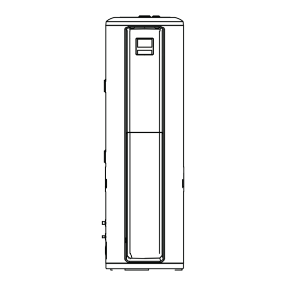
Page 9: Fixing Method
2.5 Unit outline dimension (unit: mm) Handling and Installation of water tank The water tank is soft and heavy, need more than two people to carry and install, otherwise it is easy to cause the machine to ingest and destroy into casualties. Please carry the water tank according to the factory state, do not disassemble it by yourself. - Page 10 2.4 If installed in inclosed space M8 expansion bolt fixing Wall The water heater must be located in a space >15m³, and must have unrestricted air flow. As an example, a room that has an 2.5 tall ceiling and is 3 meter long by 2 meter wide would contain 15m³ . One side wall (top view) M8 expansion bolt fixing...
-
Page 11: Installation
3. INSTALLATION 3.1 Water System Piping User Safety Valve Pipe Temp limiting valve NOTE: The temperature limiting valve is required on the hot water usage terminal. ICON One Way Valve Water Shut-off Valve Drain pipe Barrel-drain 5L-Expansion Tank for tank (if required) Accessories Function... -
Page 12: Refrigerant Circuit
Liquid pipe EXT4M80HR Ø9.52 (3/8") Ø 6.35 (1/4”) TNK190HR Ø9.52 (3/8") Ø 6.35 (1/4”) The unit installation and refrigerant piping should comply with the relevant local and national regulations for the designed refrigerant. Due to R32 refrigerant and depending on fial refrigerant charge amount, a minimum flor area for installation must be considered. -
Page 13: Electric Connection
3.3.2 Specifications of Power Supply The power supply should be an Table.3-2 independent circuit with rated voltage. Power supply circuit should be earthed Model Name TNK190HR effectively. Power Supply 220-240V~ 50Hz The wiring must be performed by MIin. Diameter of Power... -
Page 14: Installation Checklist
The unit cannot be placed into any type of closet or small 3.3.3 Switch setting enclosure. PCB has 2 bits of switches. The site location must be free from any corrosive elements in the atmosphere such as sulfur, fluorine, and chlorine. These elements are found in aerosol sprays, detergents, bleaches, For setting SG control cleaning solvents, air fresheners, paint, and varnish... -
Page 15: Trial-Running
4. TRIAL-RUNNING Emptying 4.1 Water affusion before operation After emptying, please replace the nut of Before using this unit, please follow the steps below. drainpipe. Water Affusion: If the unit is used for the first time or used again after Close emptying the tank, please make sure that the tank is full of water before turning on the power. - Page 16 Hour Min. Min. unit: ℃ unit Explenation low bit high bit Low bit Model EXT4M80HR + TANK190HR Temp./℃ Ambient 2<T4≤7 -12<T4≤-7 -7<T4≤-2 -2<T4≤2 Temp.(T4) T4<-18 -18<T4≤-12 Temp./℃ Temp./℃ COOL+DHW Temp./℃ Heat pump stop temp Ambient 7<T4≤15 Temp.(T4) 15<T4≤30 30<T4≤43 43<T4≤50 50<T4 Temp./℃...
-
Page 17: Display Explanation
Hour Min. Min. unit Explenation low bit high bit Low bit 5.2 Display Explanation Heat pump control type Heat pump 20 11 (0:Single water temperature control; control 1:Dual water temperature control) Compressor electromechanical heating belt Water tank capacity Four-way valve 0: Integral water heater 10 2 Machine type... - Page 18 ① ② ③ ⑤ Error: It will be lightened when unit is under protection/error . VACATION MODE: For the outgoing vacation mode, the water tank is set at 15°C. Maintains low tank water temperature, preheats hot water and anti-freeze lines, while reducing on/off operation of the tank.
- Page 19 Icon Description Icon Description INCREASE AND DECREASE TIMER (Daily setting) If screen is unlocked, corresponding value will 1) Press the TIMER button to the day timer icon increase by pressing the button. press the confirmation button to enter the day timer ●...
- Page 20 5.4 Priority schedule 5.3 Combination button Description Icon NOTE 1) In the main interface, press and hold the timer button for 3 If the booster heater always takes over the seconds to enter the date DHW heat load due to setting Priority setting, press the up/down button to select the date, press schedule to AC, electricity consumption will...
- Page 21 5.5 Using the SmartHome App 2) If no such message appears, proceed as follows: Tap on "+" and select your device in the list of nearby NOTE available devices. If your device is not listed, please add your device manually, first selecting the device category e.g. Water Heater.
-
Page 22: Troubleshooting
· Reorient or relocate the receiving antenna. 5.5 Compliance We, hereby declare that this device is in compliance with the · Connect the equipment into an outlet on relevant provisions of RE Directive 2014/53/EU. A copy of the full DoC is attached (Europen Union products only). a circuit different from that to which the Wireless module models: receiver is connected. - Page 23 Q: Why sometimes the buttons are unavailable? A: If there is no operation on panel for 1 min, unit will lock the panel, shows " ", to unlock the panel, please press the " " button for 2 seconds. Q: Why sometimes there is some water flowed from drainage pipe of PTR valve? A: Because the tank is pressure-bearable one, when water is heated inside the tank, water will expand, so the pressure inside of tank...
- Page 24 6.4 Error phenomenon shooting Error phenomenon Possible reason & Solution Display does not light up/water is cold. Check that the air switch is closed/set the temperature high. No hot water coming out. Check that the tap line is clear; check that the tap water pressure is not too low. Water in safety valve relief port flow If there is only a small amount of water flow out, for the water thermal expansion caused by the normal out of the pressure relief port of the...
- Page 25 Error phenomenon Possible reason & Solution When the unit reaches the temperature and stops, there may be a small deviation between the display Deviation of display from set temperature. temperature and the set temperature, which is a normal phenomenon. The use of the process in the set temperature is low, up to temperature shutdown after the display of the Reaching the temperature stopping hot amount of water may not be full grid, is a normal phenomenon, the unit can provide a certain amount of hot water is not enough.
- Page 26 Display Malfunction Description EC55 IGBT sensor failure EC56 T2b sensor failure NOTE The diagnostic codes listed above are the most common. If a diagnostic code not listed above is displayed, contact residential technical assistance referenceing the number on the front of this manual.
-
Page 27: Maintenance
7. MAINTENANCE 7.2 Recommended regular maintenance table CAUTION The maintenance of the unit requires Checking Checking Checking frequency Action professional after-sales personnel responsible Item content for overhauling the unit. air filter every month Clean the filter (inlet/outlet) 7.1 Maintenance Replace it if it has anode rod every half year been used out... -
Page 28: Made In Italy
Via San Giuseppe Lavoratore, 24 37040 Arcole, Verona +39 045 7636585 Made in Italy info@advantixspa.it www.maxa.it...
Need help?
Do you have a question about the TNK190HR and is the answer not in the manual?
Questions and answers