Table of Contents
Advertisement
Quick Links
Advertisement
Table of Contents
Troubleshooting

Related Manuals for Zehnder Rittling CALADAIR EVERSKY 500


Summary of Contents for Zehnder Rittling CALADAIR EVERSKY 500
- Page 1 ™ EVERSKY Decentralised Energy Recovery Unit Installation and commissioning manual Applicable to Manufacturing Nr 231610 → I TECHNICAL SPECIFICATIONS page 5 VIII INSTALLATION page 13 XII START-UP page 29 XIV GENERAL WIRING DIAGRAM page 38 Z-EN-V0623-CSY-INM-Zehnder Eversky, uk 1/47...
-
Page 2: Table Of Contents
™ EVERSKY Decentralised Energy Recovery Unit TECHNICAL SPECIFICATIONS ............................5 I.1. General dimensional characteristics ........................5 I.2. Dimensional characteristics specific to the hot water coil ................... 5 I.3. Electrical characteristics ............................6 I.4. External connections ............................7 I.5. Airflow connections .............................. 7 GENERAL INFORMATION ............................. - Page 3 ™ EVERSKY Decentralised Energy Recovery Unit XI.2. Stop sequence..............................28 XII. START-UP ................................29 XII.1. Setting up the time schedules ........................30 XII.2. Adjustment of ventilation setpoints and CO2 management ................31 XIII. TROUBLESHOOTING – MAINTENANCE ........................31 XIII.1. Fresh air filter pressure switch DEP FS ......................31 XIII.1.a.
- Page 4 ™ EVERSKY Safety and environment instructions • Installation and maintenance of the unit must be performed by qualified staff according to local and current standards and regulations. • Use Personal Protective Equipment to avoid damages related to electrical, mechanical (injuries from contact with metal sheets, sharp edges) and acoustics risks.
-
Page 5: Technical Specifications
™ EVERSKY SPECIFICATIONS TECHNICAL I.1. General dimensional characteristics (1) Dimension of the opening panels Location of suction and discharge outlets according to the chosen configuration Ø EVERSKY Models 1670 1297 1985 1547 1985 1547 1100 2365 1085 1050 1924 Weight EVERSKY Models 1100... -
Page 6: Electrical Characteristics
™ EVERSKY I.3. Electrical characteristics PREMIUM BE FIRST INFINITE BE Electrical Electrical SMART - INFINITE BC PREMIUM BC Temp. Model motor safety Electrical Electric Electrical Electric Electric Thermic Electrical supply EVERSKY power rating supply charge supply charge charge (°C / °C) protection* voltage voltage... -
Page 7: External Connections
™ EVERSKY I.4. External connections • (A) or (B) : Power supply Condensate drainage with condensate lift pump (hose ø6x9) (B) Gravity evacuation of condensate (hose ø10x16) • • (C) Removable outlets/blind panels I.5. Airflow connections The EVERSKY unit has modular connection ports on the fresh air intake and the exhaust extracted air allowing 9 configurations of aeraulic connection to adapt to each installation specificity. -
Page 8: General Information
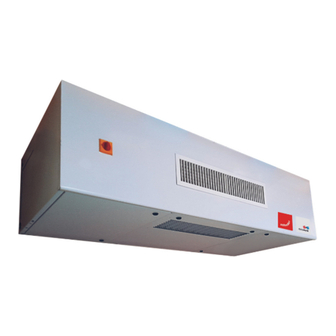
™ EVERSKY II. GENERAL INFORMATION EVERSKY is a range of high efficiency and low noise emissions decentralised ERU (Energy Recovery Unit). It features as standard an air CO2 control (DCV). Installed directly into the room or space to be treated, it avoids the need for a complex and expensive air distribution network. Featuring a high efficiency static heat exchanger, hot water or electrical coil, fresh air F7 filtration range and reinforced sound insulation, EVERSKY guarantees expected hygiene and comfort in the case of demanding rooms while limiting energy consumption. -
Page 9: Packaging And Packing
™ EVERSKY V. PACKAGING AND PACKING Sensitive parts are protected by The EVERSKY units are delivered fixed on transport supports and wrapped in a protective film. cardboard or bubble film. VI. IDENTIFICATION AND LABELLING The EVERSKY units are identified by the signage label affixed directly to a side wall. Signage label Unit size 500/700/900/1100... -
Page 10: Composition
™ EVERSKY VII. COMPOSITION VII.1. General composition Details of the composition of the unit seen from below Z-EN-V0623-CSY-INM-Zehnder Eversky, uk 10/47... -
Page 11: Vii.2. Electrical Board
™ EVERSKY Mark Designation Components Variable speed supply air fan (EC motor) Variable speed extract air fan (EC motor) Plate type recuperator with removable condensate pan Bypass with modulating motorized dumper BE+THS Supply air electrical heating coil + thermal safety switch (PREMIUM BE – INFINITE BE) BC + THA Supply air hot water heating coil + frost protection switch (PREMIUM BC –... -
Page 12: Vii.3. Control Terminal Blocks And User Connections
™ EVERSKY Mark Components Terminal block for fans supply + condensate lift pump Terminal block for safeties Terminal block for commons GDO Terminal block for commons AGND (30) Terminal block for commons G (1) → +24V Terminal block for commons +C (4) Terminal block for commons +C (4) Terminal block for commons G (1) →... -
Page 13: Installation
™ EVERSKY VIII. INSTALLATION VIII.1. Handling in an upright position It is recommended to handle the unit on its transport medias (1) and to remove them at the last moment as close as possible de the place of location. If the equipment is handled using a forklift, take care that it supports the load-bearing structure. -
Page 14: Viii.4. Coring Of The Wall Or The Ceiling
™ EVERSKY VIII.4. Coring of the wall or the ceiling If the fesh air inlet or/and the exhaust air outlet must pass through a wall, a sufficiently large opening must be provided according to the recommendations in the following table: EVERSKY A mini (mm) E (mm) -
Page 15: Viii.5.A. Attachment Of The Support To The Ceiling
™ EVERSKY VIII.5.a. Attachment of the support to the ceiling Example of unit fastening with duct connection on the back side and leaning against the wall. Step Description Remove the bracket from the top panel of the unit by unscrewing the 4 fixing screws. Note: the position of the bracket thus fitted at the factory corresponds to the clamping position once the un unit is leaning against the wall. -
Page 16: Viii.5.B. Installation Of The Unit On Its Support
™ EVERSKY VIII.5.b. Installation of the unit on its support Step Description Place the unit in horizontal position (doors below and blowing grid at the front) and remove the transport supports. Lift the unit and bring it close to its final position about 80mm from the wall and 80mm from the ceiling. -
Page 17: Viii.5.C. Installation Of The Unit In A False Ceiling
™ EVERSKY VIII.5.c. Installation of the unit in a false ceiling The unit can be semi-recessed in a false ceiling (mounting (A)) up to 10mm above the blowing grid frame. (A) Mounting in contact with the ceiling (B) Offset ceiling mounting The unit can also be offset from the ceiling (B). -
Page 18: Viii.7. Aeraulic Connection
™ EVERSKY VIII.7. Aeraulic connection Step Description Loosen the screws (F) and remove the port panels. Flip the port panels and connect them to the ducts. Tighten the screws (F). The modularity of the port panels makes it possible to position them on any side according to the diagram below: VIII.8. -
Page 19: Electrical Connection Of External Devices
™ EVERSKY Connect power supply wires directly on the main switch terminal (marker 1 and 3). Connect the protective earth (PE) wire on the crimped nut near the main switch (provide a eyelet lug for M6 screw). The protective earth wire must be slightly longer than the line and neutral wires. Power supply connection to the main switch Attach and clamp strongly the power supply cable to a fixed part (frame, cable tray…). -
Page 20: Ix.2. Heating Output (Do3) - 24Vac To Be Relayed
™ EVERSKY IX.2. Heating output (DO3) - 24Vac to be relayed Only for Premium BC and Infinite BC unit versions. Factory settings = NO (Normally Open) output. 24Vac output to be relayed. The DO3 digital output is activated when the control identifies a need for heat to comply with the temperature setpoint. -
Page 21: Ix.4. Forced Reduced Speed Digital Input (Rs=Reduced Speed) (Di3)
™ EVERSKY Hot water generator THA Frost protection 3 ways valve thermal switch θ Circulator Hydraulic principle diagram Hydraulic connection Electrical connection Respect the The axis of the valve must not be direction of oriented upside down orientation of the valve axis Respect the direction of flow of... -
Page 22: Ix.5. Forced Normal Speed Digital Input (Ns=Normal Speed) (Di4)
™ EVERSKY IX.5. Forced normal speed digital input (NS=Normal Speed) (DI4) The forced normal speed external control is used to force the unit to operate in normal speed. It is active when the contact is closed. The function has priority if the unit is: In reduced speed by the timer In reduced speed by the forced reduced speed external control Stopped by the timer. -
Page 23: Drainage Of Condensate
™ EVERSKY X. DRAINAGE OF CONDENSATE X.1. Gravity evacuation As standard, the unit is designed for a drainage of condensate by gravity (without high point). The installation of a siphon is to be expected at the time of installation of the unit. Non-compliance with the installation rules of the condensate siphon can lead to an overflow of the condensate pan and an internal flooding of the unit that can cause damages to the equipment, damages, malfunctions, and endanger the occupants and staff. -
Page 24: X.2.C. Operating Principle
™ EVERSKY X.2.c. Operating principle The pump operates autonomously as soon as the unit is switched on. It is equipped with a level controller that automatically switches the pump on and off depending on the level of condensate in the condensate pan. As standard, the pump incorporates a NC (Normally Closed) dry contact that opens when the condensate level contained in the condensate pan reaches a critical level, see XIV GENERAL WIRING DIAGRAM. - Page 25 ™ EVERSKY X.2.f.2. Installation The transparent PVC tube must not pass through any The condensate exhaust pipe must never pass through a area that may cause condensate to freeze. section that could cause the discharged condensate to freeze. Step Description Remove the part of the tube that equips in standard the unit and acting for drainage by gravity.
-
Page 26: X.2.G. Installation Of The Anti-Siphoning Device
™ EVERSKY X.2.g. Installation of the anti-siphoning device If the end of the discharge tube is below the condensate lift pump level, there is a risk of siphoning the pump which can lead to its failure by repeated dry running. To avoid this, it is therefore necessary to install the anti-siphoning device supplied in the condensate lift pump kit. -
Page 27: General Operation
™ EVERSKY Symptoms Causes and remedies The pump does not work regardless of the water Check the power supply of the pump and wiring. level in the tank. Check that the height of discharge does not exceed the maximum allowed The pump operates continuously without height. -
Page 28: Xi.1. Start-Up Sequence Of The Unit
™ EVERSKY XI.1. Start-up sequence of the unit The boot sequence is enabled when the following conditions are met: • The unit is ON, • - And there is no active Class A alarm (alarms that stop the plant), or the external shutdown control is not active, •... -
Page 29: Start-Up
™ EVERSKY XII. START-UP The clamp that holds the PG 5.0 mobile wired remote touch screen during the transport phase can be removed permanently. The EVERSKY ventilation unit is delivered preset and ready for operation. The commissioning procedure can follow the following sequence of steps: Icon Step Description... -
Page 30: Xii.1. Setting Up The Time Schedules
™ EVERSKY XII.1. Setting up the time schedules The operating principle of the EVERSKY unit is to continuously adjust the air flow according to the CO2 level measured in the room by acting on the fan speed in order to always optimize comfort and energy consumption. The time schedule is to be adapted according to the type of room occupancy, and according to whether or not the EVERSKY unit must maintain thermal comfort in this room. -
Page 31: Xii.2. Adjustment Of Ventilation Setpoints And Co2 Management
™ EVERSKY XII.2. Adjustment of ventilation setpoints and CO2 management The principle of CO2 control is to manage the speed of the fans (and therefore the airflow rate) according to the level of CO2 in the air in the room. The higher the CO2 level, and therefore the higher the occupancy rate, the faster the fans turn, and therefore the higher the airflow (air renewal). -
Page 32: Xiii.1.B. Electrical Connection
™ EVERSKY XIII.1.b. Electrical connection The filter pressure switch is of the NO type (normally open). The contact is open at rest and closes when the filter pressure drop (differential pressure) is higher than the setting (200 Pa at the factory). The pressure switch must be connected between terminals (1) and (3) according to the electrical wiring diagram. -
Page 33: Xiii.2.A. Setting The Tare
™ EVERSKY XIII.2.a. Setting the tare The nominal setting of fan pressure switches is 25Pa. There is no need to change the factory setting. This setting must be respected when the component can be replaced if necessary, which can be delivered on another setting value. The adjustment is simply done using a flat footprint screwdriver by turning the central element (1) so that the arrow (2) coincides with the set value. - Page 34 ™ EVERSKY Supply fan Extract fan Z-EN-V0623-CSY-INM-Zehnder Eversky, uk 34/47...
-
Page 35: Xiii.3. Pt1000 Temperature Sensor
™ EVERSKY XIII.3. PT1000 temperature sensor The temperature sensors are PT1000 type. The location of each temperature sensor is shown in chapter VII.1 General composition. The curve below shows the resistance characteristic of the sensitive element as a function of its temperature. The sensor is simply checked using an ohmmeter and a reference thermometer. -
Page 36: Xiii.5. Electrical Heating Coil (Be)
™ EVERSKY The output signal of the CO2 sensor is therefore never zero and should normally always be greater than 3V. In the case, conversely, have it is possible that the probe or connectors a problem. Visual representation of the CO2 probe and electrical connection terminals The 24Vac power supply is between terminals (7) and (8) and the analog signal 0-10V output is located on the terminal (2). -
Page 37: Xiii.7.A. Location
™ EVERSKY XIII.7.a. Location The THS safety thermostat is located on the support plate of the heating element see XIII.5 Electrical heating coil (BE). DBE) The THSD safety thermostat is located on the support plate of the heating element see XIII.6 Electrical frost protection coil ( XIII.7.b. -
Page 38: General Wiring Diagram
™ EVERSKY XIV. GENERAL WIRING DIAGRAM Z-EN-V0623-CSY-INM-Zehnder Eversky, uk 38/47... - Page 39 ™ EVERSKY Z-EN-V0623-CSY-INM-Zehnder Eversky, uk 39/47...
-
Page 40: Wiring Diagram Of Customer Connections
™ EVERSKY XV. WIRING DIAGRAM OF CUSTOMER CONNECTIONS Condensate lift pump: Z-EN-V0623-CSY-INM-Zehnder Eversky, uk 40/47... -
Page 41: Periodic Maintenance
™ EVERSKY XVI. PERIODIC MAINTENANCE XVI.1. Generalities Maintenance and decommissioning of the installations must be carried out under conditions that ensure compliance with the applicable environmental regulatory requirements. Maintenance must be carried out at least once a year or as required by applicable regulations (fire safety, etc.). -
Page 42: Troubleshooting
™ EVERSKY XVII. TROUBLESHOOTING First of all, check that the electrical connectors and terminal blocks are correctly connected and tightened, and that this operation has not been omitted during the start-up phase of the equipment. Also check that the screw connectors are tight. Defective parts must be replaced only with original components in order to comply with the regulations applicable to the product. -
Page 43: Aeraulic Performances
™ EVERSKY XX. AERAULIC PERFORMANCES XX.1. EVERSKY 500 XX.2. EVERSKY 750 Z-EN-V0623-CSY-INM-Zehnder Eversky, uk 43/47... -
Page 44: Xx.3. Eversky 900
™ EVERSKY XX.3. EVERSKY 900 XX.4. EVERSKY 1100 Z-EN-V0623-CSY-INM-Zehnder Eversky, uk 44/47... -
Page 45: Commissioning Report
™ EVERSKY XXI. COMMISSIONING REPORT Site Address Technician / Date ………/……../……… company Unit Manufacturing number Normal speed setp. Reduced speed setp.t High CO2 setpoint Low CO2 setpoint Ventilation setting …………………..% …………………..% …………………..ppm …………………..ppm Temperature Constant supply air Supply air Constant extract air Extract air setting temperature... - Page 46 ™ EVERSKY NOTES Date Stakeholder Comments Z-EN-V0623-CSY-INM-Zehnder Eversky, uk 46/47...
- Page 47 ™ EVERSKY Date Stakeholder Comments Z-EN-V0623-CSY-INM-Zehnder Eversky, uk 47/47...
Need help?
Do you have a question about the CALADAIR EVERSKY 500 and is the answer not in the manual?
Questions and answers