
Subscribe to Our Youtube Channel
Related Manuals for Zehnder Rittling ComfoAir 155 CM


Summary of Contents for Zehnder Rittling ComfoAir 155 CM
- Page 1 ComfoAir 155 CM Mechanical Ventilation with Heat Recovery Installation Instructions CA155CM-GB...
-
Page 2: Table Of Contents
ontents Page General Description / Physical Specification ......3 - 4 Installation Instructions .............. 4 General Preparation ..............4 Configuration ................. 5 Mounting ..................6 Access for Maintenance ............... 7 Condensate Drain ................. 7 Ducting Guidelines ............... 8 Electrical ..................9 Wiring the Unit ................ -
Page 3: General Description / Physical Specification
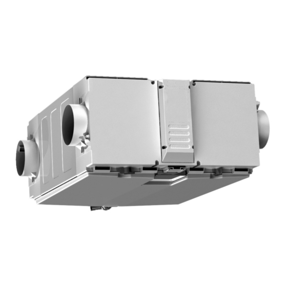
Overview 1.1.1 The ComfoAir 155 CM is a ventilation system designed to provide improved indoor air quality in dwellings. As a whole house system, the unit continuously extracts air from the non-habitable rooms and supplies fresh, filtered air to habitable rooms. Heat that is recovered from the air drawn from the bathrooms and kitchen is passed through a heat exchanger and the heat that is recovered is transferred, to temper the supply air in habitable rooms to provide a comfortable indoor environment. -
Page 4: Installation Instructions
Installation Instructions General Preparation 2.1.1 The ComfoAir 155 CM unit is supplied with 4 x 125mm Ø spigots. • 125mm ducting with connectors can be used (see Ancillary Section page 3) to provide performance levels required for compliance with local Building Regulations. -
Page 5: Configuration
Positioning 2.2.1 The ComfoAir 155 CM unit must be installed horizontally with the fixing brackets provided. 2.2.2 It is not advisable to install the unit directly above a bedroom or living room ceiling, or in an area that is part of a living area or bedroom. -
Page 6: Mounting
2.4.1 The ComfoAir 155 CM unit is supplied with two adjustable ceiling fixing brackets. Each bracket is a long strip and has four fixing points located at equal intervals. It is recommended that six screws per bracket are used to secure the unit. -
Page 7: Access For Maintenance
It is important that any condensate MUST be drained away. • The ComfoAir 155 CM unit is provided provided with a condensate drain located at the side of the unit (See Figures 6-8) and can be rotated for ease of connection. -
Page 8: Ducting Guidelines
Ducting must be connected to all four spigots according to right or left hand configuration (See Section 2.3 for Configuration). It is recommended that a minimum distance of 200mm is maintained between the ComfoAir 155 CM and any ducting bends. 2.7.3 To prevent condensation, ensure that the intake and exhaust ductwork from the unit is insulated. -
Page 9: Electrical
2.7.8 The intake fresh air should be directly from the outside. • If drawn through a wall, an external grille should be fitted. • If drawn through a roof, a recognised roof terminal should be fitted. • Ensure that the free area opening of the grille/terminal is a minimum of 90% of the free area of the ducting being used. -
Page 10: Wiring The Unit
Wiring Diagrams Key: Earth Green / Yellow Neutral Blue Brown Permanent Live Black AUX speed Grey High speed 2.9.1 Two speed control via a light switch 2.9.2 Two speed control via ZGS2 switch 2.9.3 Three speed control via ZGS1 switch 2.9.4 Three speed control via a light switch for trickle &... -
Page 11: Connecting To The Bms
System (BMS) 2.9.6 To wire into to the BMS connector within the ComfoAir 155 CM, first remove the electrical wiring cover as per Fig. 9 below then locate the BMS connector on the PCB (maintain a minimum separation distance of 35mm between the mains power and controller cables). - Page 12 Figure 12 - BMS Wiring Diagram Figure 11 - ZGRC1 Controller Note: Only one ZGRC1 boost and status controller can be installed with the ComfoAir 155 CM. Additional boost actuation should be via either 'switch-live' or standard hardwired 2-position switches. A separate AUX switch...
- Page 13 2.9.8 When wiring has been completed apply cable clamp and retain the cable sheath securely in place by tightening the cable clamp down with screw fixings. Pre-wired supply cord not shown Figure 13 - Securing BMS Wiring (Cable not supplied) 2.9.9 Refit electrical cover, taking care gasket seal underneath is seated correctly and cable is not trapped.
-
Page 14: On-Site Commissioning
On-Site Commissioning 3.1.1 This section covers set-up, configuration of the unit for installation and altering pre-set factory settings. For instructions on how to operate the LCD display user menu, maintenance options and indicator warning information, please refer to the User / Homeowner Guide. 3.1.2 Once the wiring connections have been checked, switch the mains supply on and check that the system is operating correctly. - Page 15 3.1.4 Commissioning Wizard To progress through the commissioning wizard, rotate the controls central button to required configuration and press the button to select (at each section the text will flash until it has been selected, whereby it will then go solid).
- Page 16 3.1.5 Wizard Menu Structure Installer Settings Port Configuration Rotate button to choose either RH (Right Hand) or LH (Left Hand) Configuration Extract High Factory airflow set at 66%, rotate button to required airflow % Supply High Factory airflow set at 66%, rotate button to required airflow % Extract Low Factory airflow set at 33%, rotate button to required airflow % Supply Low...
- Page 17 Refer to performance graph for ComfoAir 155 CM airflow characteristics (See Section 3.1.8). Note: All settings are stored within the ComfoAir 155 CM unit’s memory and should NOT be lost in the event of a power failure. When power is restored, the unit should revert to normal running with all settings unchanged.
- Page 18 3.1.10 Recommissioning Menu Structure Recommissioning User Menu See Homeowner Guide Service Menu See Homeowner Guide Setup Menu Password Input password 1010 to proceed into Setup Menu screens Port Configuration Rotate button to choose either RH (Right Hand) or LH (Left Hand) Configuration Extract High Wizard airflow setting will be shown .
- Page 19 3.1.11 To Modify Summer ByPass Activation Temperature When the internal and external temperature conditions are met the unit will try to maintain an indoor comfort temperature by operating the summer bypass valve. This can be adjusted as follows: • Press the control button to activate the unit. <...
-
Page 20: Guarantee
The Guarantee Period This Zehnder ComfoAir 155 CM has a 2 Year Guarantee as standard with the option to extend to a 6 Year, subject to registration. Terms and conditions apply. 4.1.1 This does not affect your statutory rights. 4.1.2 Full details available at www.zehnder.co.uk.
Need help?
Do you have a question about the ComfoAir 155 CM and is the answer not in the manual?
Questions and answers