Table of Contents
Advertisement
Quick Links
Download this manual
See also:
Manual
Advertisement
Table of Contents

Subscribe to Our Youtube Channel
Related Manuals for Zehnder Rittling ComfoD 180


Summary of Contents for Zehnder Rittling ComfoD 180
- Page 1 Ventilation system ComfoD 180 and ComfoAir 180 Manual for the installer Heating Cooling Fresh Air Clean Air ComfoD / Basic ComfoAir / Luxe...
-
Page 2: Foreword
Operating devices available for the unit. This document provides all the information required Warranty and liability conditions. for safe and optimal installation of the ComfoD 180 EEC declaration of conformity. and ComfoAir180. In this document they will be How to maintain the filters of the unit. -
Page 3: Table Of Contents
Table of Contents Foreword ................................... 2 Safety ..................................5 Installation conditions ............................. 5 Transport and unpacking ............................5 Technical specifications ............................6 4.1 Configuration unit ..............................7 4.2 Dimension sketch ..............................8 4.3 Wiring diagram ..............................10 Installation ................................12 5.1 Rework Right to Left version .......................... - Page 4 4 - EN...
-
Page 5: Safety
1 Safety 3 Transport and unpacking Always follow the safety regulations, warnings, Take the necessary precautions when comments and instructions given in this document. transporting and unpacking the unit and Personal injury or damage to the unit can arise make sure the packing material is disposed from non-compliance with the safety regulations, of in an environmentally friendly manner. -
Page 6: Technical Specifications
4 Technical specifications Sound power 1 Sound power 1 Position Ventilation capacity Power Current Silencer housing Supply fan Exhaust fan 28 m 3 /h at 3 Pa 0.08 A 27.2 dB(A) 39 dB(A) 38 dB(A) 37 m 3 /h at 6 Pa 0.09 A 27.8 dB(A) 40 dB(A) -
Page 7: Configuration Unit
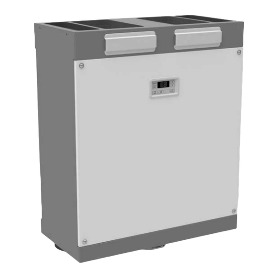
4.1 Configuration unit Position Part External casing of coated sheetsteel Interior of high-quality, expanded polypropylene EPP and ABS 5 connections for the air ducts 2 filters for air purification 2 energy-efficient DC motors with high-efficient fan HE (High efficient) heat exchanger or enthalpy exchanger (standard in unit version “Enthalpie” and “ERV”) Display to read data, and for programming procedures (not present in the unit version “Luxe”) Electronics box with the Control PCB of the unit for all the standard connections Identification plate detailing information on the unit (not visible) -
Page 8: Dimension Sketch
4.2 Dimension sketch 20 C 8 - EN... - Page 9 Legend Code Description Outdoor air Supply air Extract air Exhaust air Condensation drain EN- 9...
-
Page 10: Wiring Diagram
4.3 Wiring diagram Legend Colour code Code Colour Code Colour Code Colour (N) B Blue (L1) G Grey White (PE) G/Y Green/ Yellow (L2) Bl Black Yellow (L3) Br Brown Legend Code Decription Code Decription Pre heater NTC-Sensor Outdoor air Exhaust motor NTC-Sensor Supply air Supply motor... - Page 11 Power cord Luxe version ComfoSense Position controller EN- 11...
-
Page 12: Installation
5 Installation 5.1 Rework Right to Left version The unit with display is supplied as a Right-hand The unit version “Luxe” can be used as a Right- version (the supply and return side are on the right hand version or Left-hand version. Just mount the side of the unit). -
Page 13: Wall Mounting, Standard
5.2 Wall mounting, standard 450mm Remove the top 2 screws from the Use the screws removed to secure 1 Mount the unit against a wall rear. of the mounting brackets supplied to with a minimum mass of 200 kg/m 2 . the unit. -
Page 14: Wall Mounting, Restricted Height
5.3 Wall mounting, restricted height 450mm minimum 150mm minimum 150mm Remove the top 2 screws from the Use the screws removed to secure 1 Mount the unit against a wall rear. of the mounting brackets supplied and with a minimum mass of 200 kg/m 2 . -
Page 15: Wall Mounting, Restricted Height And Width
5.4 Wall mounting, restricted height and width 450mm Remove the top 2 screws from the Use the screws removed to secure 1 Mount the unit against a wall rear. of the mounting brackets supplied to with a minimum mass of 200 kg/m 2 . -
Page 16: Air Ducts
5.5 Air ducts 5.5.1 Top air ducts The unit’s top air duct openings can only be Legend connected using a connector from the Zehnder Code Decription ComfoPipe Plus air duct system. The following types Outdoor air of connector may be used: Supply air ■... - Page 17 Follow the steps below when the bottom supply air duct is used: Seal the top supply air duct and Release the front panel by removing Pull on the strap to remove the heat remove the seal cap from the bottom the 4 screws.
-
Page 18: Condensation Drain
5.6 Condensation drain 5.6.2 Dry syphon The condensation must be drained off frost-free, at a gradient and incorporate an air seal (U-bend or dry syphon). The connection for the condensation drain is located underneath the unit and has an external diameter of 20mm . -
Page 19: Extractor Hood (Optional)
5.8 Extractor hood (optional) 5.9 External filter (optional) It is possible to fit the ventilation system with an external filter, for instance the FilterBox from Zehnder. The external filter is part of the ducting of the Example external filter ventilation system, and does not Example extractor hood form part of the unit.
Need help?
Do you have a question about the ComfoD 180 and is the answer not in the manual?
Questions and answers