Advertisement
- 1 INTRODUCTION
- 2 THE LOWDOWN ON THE SB120 AND ITS FEATURES
- 3 GEOMETRY SB120
- 4 GEOMETRY SB120 LR
- 5 FRAME STANDARDS
- 6 KEEP YOUR YETI FRESH AND CLEAN
- 7 FRAME ASSEMBLY
- 8 BEARING PRESS ASSEMBLY
- 9 SWITCH INFINITY V2 BEARING ASSEMBLY
- 10 SWITCH INFINITY V1 BEARING ASSEMBLY
- 11 SEAT POST SET-UP
- 12 SWITCH INFINITY SERVICE
- 13 DROPPER POST INSERTION GUIDE
- 14 EXPLODED VIEW
- 15 EXPLODED VIEW PARTS LIST
- 16 REBUILD KITS
- 17 FREQUENTLY ASKED QUESTIONS
- 18 Documents / Resources
INTRODUCTION
The SB120 is made specifically for off-road use only.
This manual outlines basic setup and maintenance recommendations of your new Yeti. It is impossible to anticipate every situation or condition that may occur during the assembly, setup, and maintenance of your bicycle, Yeti recommends that all service and repairs be performed by your local authorized Yeti Dealer.
This manual contains many "Warnings" and "Cautions" concerning the consequences of failure to maintain or inspect your bicycle. The word "Warning" indicates a potentially hazardous situation in which, if not avoided, could result in serious injury or death. The word "Caution" indicates a potentially hazardous situation in which, if not avoided may result in minor injuries or damage to your bicycle or a component of your bicycle. Be sure to read and understand all of the Warnings and Cautions listed in the manual.

Make sure you review and understand the warnings, instructions, and content of this manual and accompanying manuals for your bicycle.
Technological advances have made bicycles and bicycle components more complex and the pace of innovation is increasing. It is impossible for this manual or the accompanying manuals to provide all the information required to properly repair and/or maintain your bicycle. In order to help minimize the chances of an injury, it is critical for you to have work performed by an authorized Yeti retailer.
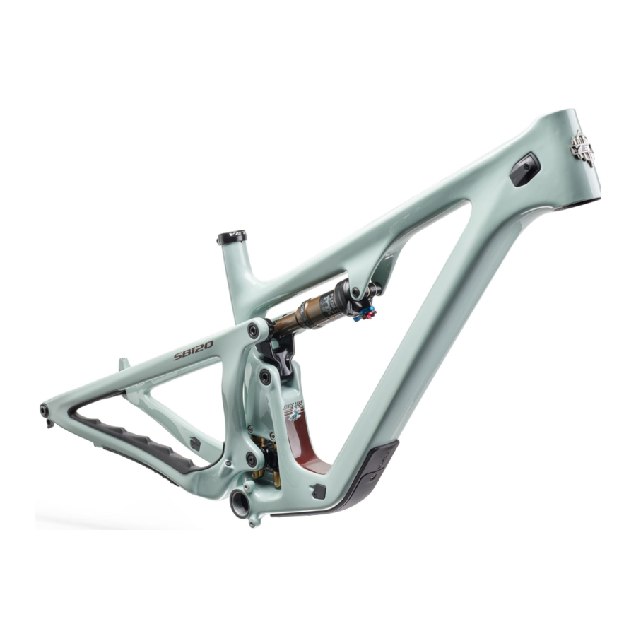
THE LOWDOWN ON THE SB120 AND ITS FEATURES
FRAME FEATURES
- SWITCH INFINITY TECHNOLOGY PATENTED SUSPENSION SYSTEM
The SB120 delivers 120mm of rear travel with our patented Switch Infinity technology. Efficient pedaling performance while still smooth and supportive when the going gets rough. - HIGH MODULUS CARBON FIBER MAIN FRAME AND SWING ARM
High modulus carbon is hand laid to create our Turq Series frames. That same stiffness and efficiency can also be found in our carbon series frame sets. - FLOATING COLLET AXLE SYSTEM ON PIVOTS INCREASES BEARING LIFE
Floating colleted pivot axles help create a perfectly aligned connection between the front and rear triangles of the frame. Allowing the enduro max sealed bearings to keep things moving freely at the pivots. - INTEGRATED ISCG-05 MOUNTS
2-bolt ISCG-05 chain guide mounts are there for you in case you need extra drivetrain security for rowdy sections. - RATTLE-FREE CABLE PORT ASSEMBLY SECURES CABLES AND HOSES TO PROVIDE A SILENT RIDE
The SB120 is designed with clamping cable ports to insure a quite ride, reduced cable movement and clean aesthetic. The ports are configurable so you can chose cable or wireless componenets without leaving behind open housing ports. - INTERNALLY MOLDED CABLE TUBES FOR HASSLE-FREE ROUTING AND A QUIET BIKE
Gone are the days of fishing your cables through your downtube hoping they pop out the other side. The SB120's internally molded cable tubes allow you to put the cable in one port and have it come out right where you want it. - INTEGRATED 41MM / 52MM TAPERED HEAD TUBE
Using an integrated head tube design on the SB120 allows for a larger head tube with more area, which results in increased stiffness, and lower overall ride height without compromising any performance. - CUSTOM DOWN TUBE PROTECTOR AND RIBBED CHAIN GUARDS TO DECREASE CHAIN SLAP NOISE
Custom seatstay, chainstay and down tube guards keep the ride quiet while protecting the frame. The nylon down tube guard keeps your bike protected where you need it most so you can focus on charging down the trail. - INTEGRATED AXLE AND UNIVERSAL DERAILLEUR HANGER SYSTEM
Dedicated 12 x 148 boost dropouts with SRAM's universal derailleur hanger (UDH) provide strength, stiffness and easy hanger and wheel installation. - CUSTOM TUNED REAR SHOCK
We develop custom suspension tunes from the ground up here in Golden, CO to optimize suspension performance to perfectly compliment the SB120 suspension kinematics. For help setting up your suspension, please visit our Shock Setup Guide.
https://shocksetup.yeticycles.com/bikes
GEOMETRY SB120


FIT
| X-SMALL | 4'10" (145 CM) – 5'3" (160 CM) |
| SMALL | 5'1" (155 CM) – 5'7" (170 CM) |
| MEDIUM | 5'5" (165 CM) – 5'11" (180 CM) |
| LARGE | 5'10" (178 CM) – 6'3" (191 CM) |
| X-LARGE | 6'1" (185 CM) – 6'7" (200 CM) |
| XX-LARGE | 6'5" (195 CM) – 6'11" (210 CM) |
GEOMETRY SB120 LR


FIT
| X-SMALL | 4'10" (145 CM) – 5'3" (160 CM) |
| SMALL | 5'1" (155 CM) – 5'7" (170 CM) |
| MEDIUM | 5'5" (165 CM) – 5'11" (180 CM) |
| LARGE | 5'10" (178 CM) – 6'3" (191 CM) |
| X-LARGE | 6'1" (185 CM) – 6'7" (200 CM) |
| XX-LARGE | 6'5" (195 CM) – 6'11" (210 CM) |
FRAME STANDARDS

| TRAVEL | 120MM |
| WHEEL SIZE | 29" |
| FRAME SIZE | XS, SM, MD, LG, XL, XXL |
| REAR SHOCK | 190MM X 45MM |
| BOTTOM BRACKET | BSA 73MMV |
| REAR WHEEL | 148MM X 12MM (BOOST) |
| SEATPOST | 31.6MM |
| CHAINLINE | 55MM |
| HEADSET | INTEGRATED 41MM/52MM TAPERED |
| REAR BRAKE POST MOUNT | 180MM |
| SHOCK HARDWARE | FRONT: M8X36MM, REAR: CUSTOM INSERT |
| MIN/MAX CHAINRING | 28T MIN/34T MAX |
| MIN MAX REAR ROTOR | 180MM MIN/203MM MAX |
| AXLE SPEC | 172MM M12X1 |
KEEP YOUR YETI FRESH AND CLEAN
MAINTENANCE OVERVIEW
Following these guidelines will help maintain the performance of your bicycle and prevent more serious problems from arising. It is important to remember that service intervals can vary depending on climate, trail conditions and riding frequency. Servicing your bike requires special knowledge and tools. If you are unsure about working on your own bicycle, contact your authorized Yeti Dealer for more information on general bicycle maintenance.
SCHEDULE

TORQUE
Yeti strongly recommends using a torque wrench when assembling your frame. Torque specifications for individual parts on the SB120 are listed below, as well as in the step by step assembly instructions later in the manual. For general bicycle maintenance please consult the torque specifications of the component you are adjusting.
KEY TORQUE SPECS
| PART # | DESCRIPTION | TORQUE (Nm) |
| 300030361 | COLLET AXLE, 15MM X 58.5L, M15X1.5 | 25 |
| 300030364 | SHOULDER SCREW, 15 X 27.35L, M15 THREAD, SS PIVOT | 25 |
| 300030376 | COLLET AXLE 15MM, 43.5L | 25 |
| 300030378 | COLLET WEDGE SUB-ASSUMBLY 15MM, M4 THREADED WEDGE BOLT | 14 |
| 300030057 | SHCS, M6 X 1.0, 20L | 12 |
| 300030377 | SHOULDER SCREW, M10 X 23L, SHOCK EYELET | 12 |
| 300030370 | SCREW, MALE, M6X12.0MM | 10 |
| 300030174 | SCREW, FH, M4 X 0.7, 16L | 2.5 |
| 300030177 | SCREW, FH, M4 X 0.7, 25L | 2.5 |
| 300030357 | SHCS, LOW PROFILE, M5 X 0.8, 16L | 5 |
| 300030173 | SCREW, FH, M4 X 0.7, 10L | 2.5 |
| 300060080 | SRAM UNIVERSAL HANGER | 25 |
| 100425018 | REAR AXLE M12X1 X 172L BOLT-ON BLACK UDH | 15 |
| 300060078 | YETI SEAT CLAMP, BOLT ON, 31.6 | 5 |
FRAME ASSEMBLY
YETI TIPS
Make sure your tools are in good condition. A worn allen key can round the hex on a bolt not allowing for proper torque.
Torque settings are listed throughout the instructions of this manual. It is important to prep all bolt threads. The instructions denote whether to use a Loctite compound or grease and part locations, listed in parentheses, are shown in the exploded view in "DROPPER POST INSERTION GUIDE". Please ensure all prep call outs are followed.
Failure to follow prep instructions could lead to serious frame issues.
Service on Yeti bicycles requires special knowledge and tools. Yeti Cycles recommends that all service and repairs be performed by an authorized Yeti Dealer.
TOOLS NEEDED
- Torque wrench(es), 5-25 Nm, CW and CCW Directions
- 2.5mm allen key
- 3mm allen key
- 4mm allen key
- 5mm allen key
- 6mm allen key
- 8mm allen key
- 10mm allen key
- 8mm guide pins
- 3" socket extender
- Blue Loctite (243)
- Grease
- Press Shaft Eyelet Spacer (3.22) into rear shock eyelet.
![]()
- Install 2X Low Profile H20 Bolts (3.25) and Washers (3.26) to front triangle.
Torque: 4 Nm (or hand tight)
![]()
- Install 2x Cable Port Clamps (3.27) to the front triangle with 2x M4 x 10L FHCS (3.31).
Install 1x Cable Port Clamp (3.27) to the rear triangle NDS Chainstay with 1x M4 x 10L FHCS (3.31).
Tighten until snug. Hardware can be torqued to 2-3 Nm after housing installation.
![]()
- Place a Head Tube Cable Port Cover (3.30) into each recess behind the head tube.
Place a Double Port Clamp (3.28) into the nondrive side cover and a Single Port Clamp (3.29) into the drive-side cover. Secure with M4 x 25L FHCS (3.24).
Tighten until snug. Hardware can be torqued to 2-3 Nm after housing installation.
![]()
- Install Lower DT Protector (3.35) to the front triangle using 3x Low Profile M5 Screws (3.25)
Torque: 5 Nm
![]()
- Assemble Switch Infinity Link (3.12) into frame using 4x SHCS (3.10) with Washers (3.11). Grease zerks should face to the non-drive side.
Torque in a cross pattern: 12 Nm.
Repeat torque to ensure all fasteners fully tight.
![]()
- Place 2x Race Extenders (3.5) onto the lower bearings in Link Assembly (3.14). Install into front triangle using Link Pivot Collet Axle (3.4) and plain Collet Nut (3.2).
Torque: 25 Nm
![]()
- Assemble Shock Extender Assembly (3.15) to SB120 Link (3.14) by placing 2X Race Extender (3.13) in the extender cavities and sliding between the link tabs. The threaded extender tab should face upwards, thru hole tab facing downward. Secure with a Guide Pin and assemble Female 8x41mm Bolt (3.17) with Washer (3.21) through the assembly. Secure with Male M6 Bolt (3.19) and Washer (3.20).
Torque: 10 Nm (or hand tight)

- Apply grease to main pivot cavities of rear triangle. Slide rear triangle assembly onto main pivot and secure with Main Pivot Collet Axle (3.1) and Routing Collet Nut (3.7), placing routing feature at the top.
Torque: 25 Nm
Install a plain collet nut (3.2, flat top with no clamp feature) if kit uses a wireless drivetrain.
![]()
- Place 2x Race Extenders (3.5) onto the upper bearings in Link Assembly (3.14). Rotate rear triangle and Link together, lining up SS Pivot bores.
Install 2x SS Pivot Screws (3.3) from the inside of the Link and partially into the rear triangle.
Place 2x plain Collet Nut (3.2) into the rear triangle.
Using a wrench from the outside of the swingarm, begin tightening in the "left-hand" direction (this is still a standard thread, but installed from the inside), tightening the SS Pivot Screw and Collet Nut.
Torque: 25 Nm

- Install Large Collet Wedge Bolts (3.9) into
2x Collet Axles (3.1) and (3.4)
Torque: 14 Nm
![]()


QC CHECK
Cycle rear triangle through to make sure motion is smooth.
Take precaution to make sure link does not contact seat tube.
- Install the shock into the frame by securing front eyelet with a Guide Pin. Install Shock Extender Screw (3.16) through the lower extender tab, through the Shock, and thread into the upper extender tab (3.23). Use a socket bit extender to help gain clearance between wrench and Link.
Torque: 12 Nm
Take precautions to prevent the shock striking/ contacting the downtube.
![warning]() Note: RockShox Superdeluxe Lunch Ride spec shock must be deflated to install/remove on XS sized frames.
Note: RockShox Superdeluxe Lunch Ride spec shock must be deflated to install/remove on XS sized frames.
![]()
- Install Female 8x45mm Bolt (3.18) with Washer (3.21) through front Shock Eyelet and secure with M6 Male Bolt (3.19) and Washer (3.20)
Torque: 10 Nm
![]()
- Install Housing Clamp Cap (3.8) onto the driveside main pivot axle with a M4 x 16L FHCS (3.23)
Tighten until snug. Hardware can be torqued to 2-3 Nm after housing installation.
![]()
- Install a Housing Clamp Cap (3.8) and Clamp Base (3.6) onto the non-drive main pivot wedge bolt with a M4 x 25L FHCS (3.24).
Tighten until snug. Hardware can be torqued to 2-3 Nm after housing installation.
![]()
- Install Univesal Hanger (3.34) into frame. Do not use grease. Note that hanger cap bolt is reverse threaded.
Torque: 25 Nm
![]()
 Note: RockShox Superdeluxe Lunch Ride spec shock must be deflated to install/remove on XS sized frames.


BEARING PRESS ASSEMBLY
LINK BEARING PRESS

- Press both upper bearings into the link from the inside of the link tabs using a 15x24mm arbor. Check that both bearings are fully seated.
- Press the drive-side lower bearing into the link using a 15x24mm arbor, fully seating the bearing into the link.
- Install the lower bearing spacer against the pressed lower bearing. Press the non-drive side bearing into the link until bearing bottoms against the spacer
EXTENDER BEARING PRESS

- Press the drive-side bearing (orientation of extender with the threaded tab on top) with the extended race facing inward. Press into the extender until fully seated.
- Press the non-drive side bearing into the extender with the extended racing facing inward. Press until the bearing contacts the drive-side bearing.
SWITCH INFINITY V2 BEARING ASSEMBLY
BEARING REMOVAL

- Remove dust caps on the outside of the bearings.
- Remove non-drive side bearing.
- Remove axle sleeve from drive side bearing.
- Remove drive side bearing.
BEARING INSTALL

- Press drive side bearing into Switch Infinity body.
- Slide axle sleeve into drive side bearing.
- Press non-drive side bearing onto sleeve.
- Replace bearing caps.
SWITCH INFINITY V1 BEARING ASSEMBLY
BEARING REMOVAL

- Remove drive side bearing and axle sleeve
- Remove non-drive side bearing
BEARING INSTALL

- Press non-drive side bearing into switch infinity housing (ensure extended race is facing outward from switch infinity body).
- Place axle sleeve in body and press drive side bearing into housing
SEAT POST SET-UP
STANDARD ROUTING SET-UP
- With a 3mm allen wrench, remove the outer plastic downtube protector.
![]()
- Install your seatpost housing into the drive-side head tube port, pushing until it exits near the downtube cable port access hole.
![]()
- The hole under the downtube protector provides an access point to use your finger to help push the housing around the bend in the frame up into the seat tube.
![]()
- While pushing the housing into the head tube port, continue guiding the cable up the seat tube through the access hole until the housing exits the seat tube.
![]()


SWITCH INFINITY SERVICE
- With a 2.5mm allen wrench, remove the two clamps securing the shifter and brake housing to the main pivot.
![]()
- With a 5mm allen wrench, remove the main pivot Collet Wedge Bolt (3.9).
![]()
- With a 10mm allen wrench, remove the Main Pivot Collet Axle (3.1).
![]()
- Rotate your swingarm upwards to expose the Switch Infinity Link and access both grease zerks. With a clean rag and mild detergent, clean any mud, dust, or debris off the Switch Infinity Link.
![]()
- Remove the two dust caps from the Switch Infinity Link. Clean any debris or dust off the dust caps and bearing races in the Switch Infinity Link. Reinstall dust caps when finished.
![]()
- Using a needle-type grease gun, push new grease into the two Switch Infinity grease ports until you see fresh grease extruding from the shaft seals. Wipe off any excess grease that was pushed out of the seals.
![]()
- Apply assembly grease to the Main Pivot Collet Axle (3.1) shaft and head and apply anti-seize to the threads. Lower the swing arm and re-install your Main Pivot Collet Axle (3.1).
Torque: 25 Nm.
![]()
- Apply assembly grease to the Main Pivot Collet Wedge head and threads. Install into the Main Pivot Collet Axle (3.1).
Torque: 14 Nm.
![]()
- Re-install the housing clamps at the main pivot. Place a single clamp onto the shifter housing and secure with a M4 x 16L screw. Place a clamp and clamp base around the brake housing and secure with a M4 x 25L screw. Tighten until snug.
![]()


EXPLODED VIEW

- Clamps
- Collet Wedge Bolt (3.9)
- Main Pivot Collet Axle (3.1)
- Main Pivot Collet Wedge
DROPPER POST INSERTION GUIDE
Droppers are an essential tool for the modern mountain bike but proper clearance checks are required before heading out for your first ride.
The key checks are as follows:
Ensure your dropper is short enough to fit into the seat tube without interfering with the frames structure but you are still able to achieve your desired BB-Saddle measurement. See the max insertion depth chart to confirm this distance for wired and wireless posts.
There are some scenarios where you can fit a longer dropper in your frame but when you drop your dropper the saddle or battery for AXS posts could interfere with your tire during a suspension compression. See the Min BB-Saddle at full drop to confirm this distance.
Always perform a final check to ensure your post is installed to at least the minimum insertion line. Also, compress the dropper and suspension, let the air out of your shock, to ensure there is no tire interference to the saddle or AXS battery at full bottom out.
We strive to spec out dropper lengths to provide the maximum drop for the highest percentage of our riders. There is a wide range of saddle heights for every frame size. There is a possibility saddle height could fall outside of this range. A small percentage of customers might find they require a shorter or longer post given their saddle height.
Please ensure you check the minimum dimensions in the below tables before going for your first ride. Failure to do so could result in tire to saddle rub or tire to battery contact for AXS posts.
Please confirm both of these measurements, they are both required to ensure proper dropper fitment.
If you have any questions, please contact Yeti or your local bike shop.
MINIMUM BB TO SADDLE CABLED DROPPER (MM)*

| FRAME SIZE | X-SMALL | 498.5** |
| SMALL | 497.4** | |
| MEDIUM | 496.5** | |
| LARGE | No min | |
| X-LARGE | No min | |
| XX-LARGE | No min |
*These measurements are only for cabled droppers. Please make sure if you have a wireless post you confirm that there is not any interference of the tire hitting the battery when the post is fully dropped and the suspension is fully compressed.
**If you go lower then listed minimum you run the risk of tire to saddle interference.
MAX INSERTION WIRELESS DROPPER (MM)*

| FRAME SIZE | X-SMALL | 232.2 |
| SMALL | 242.8 | |
| MEDIUM | 277.4 | |
| LARGE | 316.8 | |
| X-LARGE | 331.0 | |
| XX-LARGE | 331.0 |
*Subtract 34mm for a cabled dropper to accommodate housing bend angle.
EXPLODED VIEW

PREP KEY

EXPLODED VIEW PARTS LIST
| ITEM # | PART # | DESCRIPTION | TORQUE (NM) | QTY |
| 1 | SB120 FRONT TRIANGLE ASSEMBLY | 1 | ||
| 1.1 | SB120 FRONT TRIANGLE ASSEMBLY | 1 | ||
| 2 | SB120 SWINGARM ASSEMBLY | 1 | ||
| 2.1 | SB120 SWINGARM | 1 | ||
| 3 | SB120 SMALL PARTS ASSEMBLY | 1 | ||
| 3.1 | 300030361 | COLLET AXLE, 15MM X 58.5L, M15X1.5 | 25 | 1 |
| 3.2 | 300030362 | COLLET NUT, M15, 9.5 THICK, ROUND CAP | 4 | |
| 3.3 | 300030364 | SHOULDER SCREW, 15 X 27.35L, M15 THREAD, SS PIVOT | 25 | 2 |
| 3.4 | 300030376 | COLLET AXLE 15MM, 43.5L | 25 | 1 |
| 3.5 | 300030365 | RACE EXTENDER, 25 X 15.1 X 3.35 | 4 | |
| 3.6 | 300030366 | CLAMP BASE, 23MM X 3.5T, BRAKE HOUSING | 1 | |
| 3.7 | 300030367 | COLLET NUT, M15 X 1.5, SHIFTER HOSE CLAMP | 1 | |
| 3.8 | 300030368 | CLAMP CAP, HOUSING | 2 | |
| 3.9 | 300030378 | COLLET WEDGE SUB-ASSEMBLY 15MM, M4 THREADED WEDGE BOLT | 14 | 2 |
| 3.10 | 300030057 | SHCS, M6 X 1.0, 20L | 12 | 4 |
| 3.11 | 300030214 | WASHER 6.3 X10.0 X 1.0 MM | 4 | |
| 3.12 | 200020422 | ASSY, SWITCH INFINITY, MECHANISM, FACTORY SERIES | 1 | |
| 3.13 | 300030375 | SHOCK EXTENDER BEARING EXTENSION | 2 | |
| 3.14 | 200020420 | SB120 LINK ASSEMBLY | 1 | |
| 3.14.1 | 300040539 | SB120 LINK | 1 | |
| 3.14.2 | HNA00000BA0 0000000000 | BEARING, 3802-2RS, 15 X 24 X 7 | 4 | |
| 3.14.3 | 300030369 | SPACER, 15.2 X 17 X 7.3L | 1 | |
| 3.15 | 200020421 | ASSY, SHOCK EXTENDER, SB120 | 1 | |
| 3.15.1 | 300040543 | SHOCK EXTENDER, SB120, 25MM | 1 | |
| 3.15.2 | 300020032 | BEARING, 398 MAX DBL, 8 X 19 X 10/11 | 2 | |
| 3.16 | 300030377 | SHOULDER SCREW, M10 X 23L, SHOCK EYELET | 12 | 1 |
| 3.17 | 300030372 | BOLT, FEMALE, 8 X 41.0, M6 THREAD | 1 | |
| 3.18 | 300030371 | BOLT, FEMALE, 8 X 41.0, M6 THREAD | 1 | |
| 3.19 | 300030370 | SCREW, MALE, M6X12.0MM | 10 | 2 |
| 3.20 | 300030062 | WASHER 6.5 X 12.5 X 0.5 MM | 2 | |
| 3.21 | 300030069 | WASHER 8.5 X 12.5 X 0.5 MM | 2 | |
| 3.22 | 300030374 | SHOCK EYELET SPACER | 1 | |
| 3.23 | 300030174 | SCREW, FH, M4 X 0.7, 16L | 2.5 | 1 |
| 3.24 | 300030177 | SCREW, FH, M4 X 0.7, 25L | 2.5 | 3 |
| 3.25 | 300030357 | SHCS, LOW PROFILE, M5 X 0.8, 16L | 5 | 5 |
| 3.26 | 300030358 | WASHER 5.2 X 8.8 X 1.0 MM, STAINLESS ED BLACK | 2 | |
| 3.27 | 300040518 | COVER-CABLE PORT, SINGLE, RIGHT EXIT | 3 | |
| 3.28 | 300040522 | CLAMP, HT PORT DOUBLE, PA6 | 1 | |
| 3.29 | 300040521 | CLAMP, HT PORT SINGLE, PA6 | 2 | |
| 3.30 | 300040524 | CABLE PORT COVER, HEAD TUBE, 2 PIECE | 2 | |
| 3.31 | 300030173 | SCREW, FH, M4 X 0.7, 10L | 2.5 | 3 |
| 3.32 | 300060080 | SRAM UNIVERSAL HANGER | 25 | 1 |
| 3.33 | 300060078 | ASSY, YETI SEAT CLAMP, BOLT ON, 31.6 | 1 | |
| 3.34 | 300040523 | COVER, HT PORT, BLIND, PA6 | 1 | |
| 3.35 | 200020418 | DT GUARD, MY23 OUTER, PA/ABS | 1 | |
| 3.36 | 300040542 | COVER-CABLE PORT, BLANK, RIGHT EXIT | 1 | |
| 3.37 | 300040510 | FRAME PLUG, CABLE PORT | 2 | |
| 3.38 | 100425018 | REAR AXLE M12X1 X 172L BOLT-ON BLACK UDH | 15 | 1 |
| 4 | SB120 SHOCK SUB ASSEMBLY | 1 |
REBUILD KITS


FREQUENTLY ASKED QUESTIONS
WHAT IS THE DIFFERENCE BETWEEN THE TURQ AND CARBON SERIES SB120?
TURQ Series bikes are manufactured with the highest quality and best-performing carbon fiber available and offer the perfect balance of stiffness, durability, and compliance. The result is a bike that feels smooth, solid and aggressive. Carbon series bikes use a modified carbon fiber layup of our TURQ Series bikes. By using different materials and tweaking the fiber layup, we are able to make a more aggressively priced carbon high-performance mountain bike while maintaining the strength and stiffness of its higher end sibling. The carbon series SB120 weighs a bit more, about 200g for a frame.
WHAT IS SWITCH INFINITY TECHNOLOGY AND HOW DOES IT WORK?
Switch Infinity utilizes a patented translating pivot that automatically switches direction as the bike moves through its travel. This provides excellent anti-squat characteristics for superior pedaling performance and ideal suspension characteristics as it gets deeper into the travel. Inside are a pair of greased bushings that slide up and down on two Kashima coated rails – it's not an extra shock that needs to be filled with air. Just keep it greased and wiped clean per our maintenance recommendations below.
DOES THE SWITCH INFINITY SYSTEM REQUIRE MAINTENANCE?
The fully sealed Switch Infinity mechanism has external grease ports to lube the bushings and seals. Yeti and development partner Fox Racing Shox recommend a lubrication interval of 40 hrs of riding. It is important not to over lube the system and adhere to the recommended interval. It also doesn't hurt to wipe off any excess dust and dirt that may accumulate throughout the week. Any maintenance supplies you need can be found on our webstore or at your local dealer.
For detailed maintenance information, please visit https://www.ridefox.com/fox17/help.php?m=bike&id=465
CAN I REPLACE OR MODIFY ANY YETI FRAME PARTS ON MY SB120?
All replacement frame parts for your SB120 can be found through your local dealer or on our webstore. Only genuine Yeti parts should be used when replacing any parts on your frame. We know there are a lot of aftermarket products out there that seem legit but we do not have the ability to qualify and ensure all of these products are safe to use on our frames. If it is found that any frame part has been modified or replaced all warranties will be voided and all liability will be assumed by the customer.
CAN I CHANGE OR UPGRADE THE SPEC COMPONENTS ON MY SB120?
There are many options in aftermarket parts to upgrade or personalize your bike. Some parts are standardized, especially from the big brands like Fox, Shimano, SRAM etc. You should always confirm with a professional mechanic that your parts are the correct standard and correctly and securely mount to your bike without any interference or play. Pay special attention to all the bikes standards and check the fit before use
CAN I USE AN ANGLESET ON THE SB120?
The SB120 was designed with an integrated headset which has the headset cups molded into the frame so you can easily drop the bearings into the cups. There are some aftermarket anglesets available for this style headset however the frame was not tested for the use of these and therefore should not be used. Yeti's warranty will be voided if it is found an angle-set was installed on the frame and all liability will be assumed by the customer. See "What travel fork is the SB120 designed to use" for more information.
WHAT TRAVEL FORK IS THE SB120 DESIGNED TO USE?
The SB120 is designed to run a 130mm travel fork. We tested this frame to 20mm over the spec fork. So if you're feeling the need to beef up the fork you can run up to a 150mm fork no problem. Bottom line - max axle to crown measurement of 564mm. Increasing your fork travel will slacken the head angle and seat tube angle and raise the bottom bracket. Running a shorter fork is fine too if that suits you. Shortening the fork will steepen the head angle and seat tube angle and lower the bottom bracket. For more geometry information, check out the geometry section.
HOW BIG OF A TIRE CAN I FIT ON THE SB120?
The short answer is the SB120 can accept up to a 2.6" tire. There is great tire clearance on the SB120 but tire sizes vary widely by manufacturers, so it is hard to give a number that works for all brands.
CAN I FIT A WATER BOTTLE INSIDE THE FRONT TRIANGLE?
Yes, we designed the SB120 to accommodate a standard sized water bottle inside the front triangle for sizes MD-XXL. Size XS will fit Yeti's 15oz Hot Lap bottle and size SM will fit standard 21oz bottles. We recommend using a side-entry cage for easiest access.
WHAT CRANKS AND BOTTOM BRACKET CAN I USE ON THE SB120?
The SB120 bottom-bracket standard is BSA 73mm and only wide "q" factor cranks are compatible. It is readily compatible with Shimano, SRAM, and RaceFace cranks, but a fit check is required for other brands.
WHAT REAR WHEEL AXLE FITS ON MY SB120?
The SB120 is designed to work exclusively with SRAM's Universal Derailleur Hanger at 12x148mm spacing. This axle had a thread pitch 12x1.0 and a length of 172mm. Note that this axle is only compatible with frames specifically designed with the Universal Derailleur Hanger.
WHAT TYPE OF HEADSET DOES THE SB120 USE?
The SB120 uses an Integrated 41mm/52mm tapered headset. This system allows for the headset bearings to be contained inside the head tube for an overall lower ride height, more simplified installation, and increased stiffness.
HOW BIG OF A ROTOR WILL FIT ON THE FRAME?
The SB120 has a direct mount rear brake tab and can run a 180mm rotor without the need for a brake adaptor. With the use of a brake adaptor the frame can accept up to a 203mm rotor.
CAN I RUN A STEALTH SEATPOST DROPPER ON THE SB120?
Yes. The SB120 has routing options for stealth only.
WHAT CHAINLINE WAS THE SB120 DESIGNED AROUND?
The SB120 was designed around a 55mm Boost chainline. Depending on the crank and chain ring configuration you can run other chainlines but you will have to do a clearance check first.
WHAT IS THE MAX SIZE SINGLE-CHAINRING THAT FITS ON THE SB120?
Without getting too technical, the max chainring size depends on the crank chainline and the chainring shape.
- Shimano / SRAM 55mm chainline Boost cranks: 34t round / 32t oval
- Minimum Chainring Size: 28t round / 30t oval Confused? Ask your local dealer or call us 303.278.6909.
DOES THE SB120 HAVE ISCG MOUNTS?
Yes. The SB120 has an integrated 2-bolt ISCG '05 mount. It is designed to work best with low profile modern guides; depending on the brand, some older models with larger upper guides may not fit. We always recommend performing a fit-check with a specific chain guide to confirm compatibility.
WHAT TYPE OF SHOCK DOES THE SB120 USE?
The SB120 uses a 190 x 45mm shock. The shock can also be locked out if you so desire, but we recommend running it fully open for the best compliance and traction.
HOW DO I INSTALL MY ROCKSHOX SUPERDELUXE SHOCK ON MY XS SIZED FRAME?
RockShox Superdeluxe shocks must be deflated to install/remove on XS sized frames. Attach a shock pump to the shock and slowly deflate the shock until the shock length is reduced.
WHAT TYPE OF SHOCK HARDWARE DOES THE SB120 USE?
The SB120 uses M8x36mm hardware on the air can side and a custom Yeti reducer on the shaft side. If you swap between shocks, the reducer can be found here,
https://yeticycles.com/gear/detail/shock-eyelet-spacer
CAN I PUT A COIL SHOCK ON MY SB120?
No, the SB120 will not fit a coil shock due to sizing constrictions and limited frame clearance in the bike's link.
WHAT PERCENTAGE SAG DO YOU RECOMMEND FOR THE SB120?
We would advise starting with 30% sag, or 13.5mm of shock stroke for optimal pedaling efficiency and terrain compliance. Be sure to set your sag at your normal riding weight, gear included. Feel free to venture slightly above or below 30% to suit your personal preference.
Visit our shock set up page to help set up your suspension,
https://shocksetup.yeticycles.com/calculator
WHAT SIZE SEAT POST DOES THE SB120 USE?
The SB120 uses a 31.6mm seat post.
WHAT SIZE SEAT COLLAR DOES THE SB120 USE?
The SB120 uses a 36.4mm seat collar.
WHAT IS THE WARRANTY ON MY SB120?
The SB120 has a LIFETIME manufacturer's warranty.
WHAT IS THE LONGEST TRAVEL DROPPER POST I CAN RUN ON THE SB120?
This is mostly defined by your inseam. There is no frame limitation, so in theory, you can run any travel as long as you are above the minimum insert mark and you are not so low your tire rubs on your saddle. Your local Yeti dealer can help you sort this out. We run 150mm drop on SM-XS frames, 175mm on MD and 200mm drop on LG-XXL.
CAN I CONVERT THIS BIKE INTO A "MULLET" BIKE AND PUT A 27.5" WHEEL ON REAR OF THE SB120?
It is possible, but we would not suggest it as it would lower your BB too much and slacken your head tube angle and seat tube angle. But hey, if those changes suit your ride style then go for it.
Documents / Resources
References
![shocksetup.yeticycles.com]() https://shocksetup.yeticycles.com/bikes
https://shocksetup.yeticycles.com/bikes![www.ridefox.com]() Yeti Infinity Link User Guide | Bike Help Center | FOX
Yeti Infinity Link User Guide | Bike Help Center | FOX![yeticycles.com]() SHOCK EYELET SPACER - Yeti Cycles
SHOCK EYELET SPACER - Yeti Cycles![shocksetup.yeticycles.com]() https://shocksetup.yeticycles.com/calculator
https://shocksetup.yeticycles.com/calculator![yeticycles.com]() Yeti Cycles Home - Yeti Cycles
Yeti Cycles Home - Yeti Cycles
Download manual
Here you can download full pdf version of manual, it may contain additional safety instructions, warranty information, FCC rules, etc.
Advertisement


Need help?
Do you have a question about the SB120/LR and is the answer not in the manual?
Questions and answers