Table of Contents

Related Manuals for Paul Agnew Ilektro 1250 Tunnel


Summary of Contents for Paul Agnew Ilektro 1250 Tunnel
- Page 1 ilektro Range MODEL 1250 Tunnel 1250 - BAY MK II SPECIFICATION SHEET Version 1 02/01/23 Contents of manual may be updated without notice. For the latest version of this manual please refer to our website: www.paulagnewdesigns.com.au...
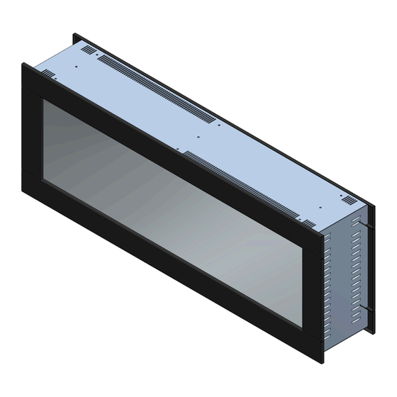
- Page 2 1250 Tunnel APPLIANCE DIMENSIONS Product Code: 1250 Tunnel MODEL 1250 - GF MK II 1217 1249 FRAME BUILD OUT DIMENSIONS (All dimensions are in millimetres) H - MIN C - CAVITY DEPTH W - MIN 1245 1165 NOTE: Remove trim as per the step...
-
Page 3: Installation Steps
1250 Tunnel INSTALLATION PROCEDURE Product Code: 1250 Tunnel INSTALLATION STEPS: A. Measure the appliance and create an opening to fit the fire into. See Fig 1 B. Create a route for the electrical connection. C. Remove the front trims, see below. -
Page 4: Front Glass Removal
1250 Tunnel INSTALLATION PROCEDURE Product Code: 1250 Tunnel D. Remove the front glass, see below. Front Glass Removal 1250 - GFL MK II WARNING: BEFORE THE FRONT GLASS IS INSTALLED OR REMOVED UNPLUG THE APPLIANCE AND WAIT UNTIL THE APPLIANCE IS COOL TO THE TOUCH. GLASS CAN BE HEAVY AND FRAGILE SO HANDLE WITH CARE. - Page 5 1250 Tunnel INSTALLATION PROCEDURE Product Code: 1250 Tunnel E. Install mounting bracket by aligning the edge 6.4mm from the center of the wall sides and 156mm from the bottom of the wall sides. Fig. 6 1250 - GFR MK II...
-
Page 6: Front Glass Installation
1250 Tunnel INSTALLATION PROCEDURE Product Code: 1250 Tunnel I. Install the log set to suit your own style. Install the front trim by aligning with the pins on the appliance. This ensures the touch display panel performs properly. Installation - Suggested Log Layout... -
Page 7: Front Trim Installation
1250 Tunnel INSTALLATION PROCEDURE Product Code: 1250 Tunnel Front Trim Installation A. Lift the trim and ensure the trim top lines up with the appliance top, then push in until the trim drops 1250 - GFR MK II down and sits on the appliance by aligning the slots in the trim with the pins on the appliance. Fig 12. -
Page 8: Exploded View
1250 Tunnel Note: Above given dimensions are for frame structure only. EXPLODED VIEW ilektro Range... - Page 9 148 Cochranes Road Moorabbin, Victoria 3189 www.paulagnewdesigns.com.au info@paulagnewdesigns.com.au ilektro Range...
Need help?
Do you have a question about the Ilektro 1250 Tunnel and is the answer not in the manual?
Questions and answers