
Related Manuals for Daikin Rotex GW-20 C28


Summary of Contents for Daikin Rotex GW-20 C28
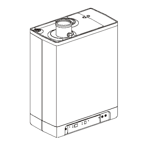
- Page 1 ROTEX Condensing Boiler Installation instructions Wall-mounted Gas Condensing Boiler GW-20 C22 / RKOMB22AAV1H GW-20 C28 / RKOMB28AAV1H GW-20 C33 / RKOMB33AAV1H...
- Page 2 2P369568-2B...
-
Page 3: Table Of Contents
TABLE OF CONTENTS Safety instructions Unit description General ......................................5 Functioning ...................................... 5 Operating modes ..................................... 5 PC Interface ....................................7 Test programs ....................................7 Main components Accessories ..................................... 9 Installation Installation measurements ................................10 Installation space ................................... 12 Assembly ....................................... 13 Connecting Connecting CH installation ................................ - Page 4 These installation instructions With these installation instructions, you can safely assemble, install and maintain the unit. Carefully follow the instructions. In case of any doubt, please contact the manufacturer. Keep the installation instructions near the unit. Abbreviations and terms used Description To be referred to as High Efficiency...
-
Page 5: Safety Instructions
SAFETY INSTRUCTIONS The manufacturer ROTEX Heating Systems GmbH accepts no liability for damage or injury caused by the failure to (strictly) observe the safety instructions, or negligence during the installation of the Rotex RKOMB*AAV1H wall-mounted gas boiler and any associated accessories. This device is not intended for use by people (including children) with reduced physical, sensory or mental abilities, or lack of experience and knowledge, unless they are given supervision or instructions on the use of the device by a person who is... - Page 6 Post-running After the end of the CH-operation, the pump will run for a specified time. The post-pumping time is set to the value in par. 7.2 in its factory settings. This setting can be changed. In addition to this, the pump will run automatically 1 time per 24 hours, for 10 seconds, in order to prevent it from getting stuck.
-
Page 7: Pc Interface
temperature (this temperature can be set, see par. 7.2). The tap comfort function has the following settings: On: ( LED on) The tap comfort function of the unit is continuously switched on. • The unit always immediately provides warm water. Eco: ( LED on) The tap comfort function of the unit is self-learning. -
Page 8: Main Components
MAIN COMPONENTS CH pump Air supply (only when using twin pipe flue system) Gas valve Flue gas/air inlet concentric adapter Burner controller (incl. operating panel) Connection block / terminal strip X4 Sensor S1 (flow) Condensate drain pan Sensor S2 (return) Domestic hot water sensor S3 Siphon Flow sensor... -
Page 9: Accessories
Accessories Description Article numbers B-pack small EKFJS*AA B-pack middle EKFJM*AA B-pack large EKFJL*AA Valve kit EKVK4AA Cover plate EKCP1AA Outdoor sensor EKOSK1AA 3-Way valve set EK3WV1AA Flue gas adapter Concentric 80x125 EKHY090717 Ø Flue gas adapter Parallel 80 mm EKHY090707 Propane conversion set *KOMB28AAV1 EKHY075787 &KOMB33AAV1... -
Page 10: Installation
INSTALLATION Installation measurements Unit with pipes connected downwards: Unit + wall mounting strip Supply CH G ¾” (ext) Return CH G ¾” (ext) G ½” (int) Tap water cold R ½” Tap water warm R ½” Condense outlet Ø dn25 (flexible) 517mm RKOMB22AAV1H 577mm... - Page 11 Unit connected to B-pack: Unit + B-pack Supply CH G ¾” (ext) Return CH G ¾” (ext) G ½” (int) Tap water cold R ½” Tap water warm R ½” Condense outlet Ø dn25 (flexible) 770mm RKOMB22AAV1H 830mm RKOMB28AAV1H 890mm RKOMB33AAV1H Z2 = Smoke gas outlet/air inlet Ø60/100 (concentric) ROTEX Heating Systems GmbH...
-
Page 12: Installation Space
Installation space The unit must be installed against a wall with sufficient load bearing capacity. In case of light wall constructions, there is a risk of resonance noises. Within 1 meter of the unit, there must be a earthed wall plug. In order to prevent the condense outlet from freezing, the unit must be installed in a frost-free room. -
Page 13: Assembly
Assembly The boiler can be hung to the wall using : the wall suspension strip and a the connection kit EKVK4AA • a B-pack including an expension vessel and a connection kit. • 4.3.1 Assembling suspension strip and assembly bracket Make sure the construction of the wall is suitable for hanging the boiler. - Page 14 4.3.3 Assembling unit Unpack the unit. Check the content of the packaging, which consists of: • Unit (A) • Suspension strip (B) • Sifon (C) + flexible hose • Installation instructions • Operating instructions • Guarantee card Check the unit for any damage: immediately report damages to the supplier. Install the suspension strip.
-
Page 15: Connecting
CONNECTING Connecting CH installation Rinse the CH installation carefully. Fit the supply pipe (A) and return pipe (B) to the connection set. All pipes must be assembled with no electrical current, in order to prevent shocks from the pipes. Existing connections may not be rotated, in order to prevent leakages. The CH installation must be fitted with: A filling/draining tap (A) in the return pipe, immediately underneath the unit. - Page 16 Underfloor heating distributor without pump Connect the underfloor heating system (D) and set the maximum CH supply temperature of the boiler to the design condition. Fit a clamp thermostat (A) onto the supply tube underneath the boiler. The clamp thermostat with blind cap must be set to a maximum supply temperature of 55°C.
-
Page 17: Connecting Dhw Installation
Connecting DHW installation Rinse the installation carefully. If required, assemble an inlet combination. Assemble the cold (D) and warm water pipe (C) to the connection set. Comments If the unit is only used for warm water supply, the heating function can be switched •... -
Page 18: Connecting Electronically
Connecting electronically CAUTION A socket with safety ground must be no further than 1 meter from the unit. The socket must be easily accessible. When installing the unit in damp space, a fixed connection is obligatory, by means of an all-pole main switch with a minimum contact gap of 3 mm. -
Page 19: Connect Room Thermostat
Connect room thermostat 5.4.1 Room thermostat on/off 1. Connect the room thermostat (see par. 10.1). 2. If necessary, set the feedback resistance of the room thermostat to 0.1 A. If unsure, measure the electrical current and set it accordingly. The maximum resistance of the thermostat pipe and the room thermostat amounts to a total of 15 Ohm. -
Page 20: Connecting Gas
Undo the appointment of an RF room thermostat to the CH boiler. Press the reset button of the unit for approximately 5 seconds to • access the RF room thermostat menu of the CH boiler. button 2x. On the display above the Press the service button, a •... -
Page 21: Flue Gas Output And Air Input
Flue gas output and air input For the installation of the flue gas output and air input material, we refer to the enclosed basic manual, or contact the manufacturer of the appropriate flue gas output and air input equipment for extensive technical information and specific assembly instructions. -
Page 22: Outlet Systems
Outlet systems Please note that not all flue gas configurations described below are permitted in all countries. Therefore observe local regulations prior to installation. 5.7.1 Pipe lengths As the resistance of the flue tube and air supply pipes increases, the power of the unit will decrease. - Page 23 5.7.3 Permitted pipe lengths at parallel air supply and flue tube systems Permitted pipe lengths when applying Ø80 mm. C33 (*) RKOMB22AAV1H 100 m 100 m 100 m 100 m 100 m RKOMB28AAV1H 85 m 85 m 85 m 85 m 85 m RKOMB33AAV1H 80 m...
- Page 24 5.7.5 General assembly: For all outlets, the following assembly applies: Slide the combustion gas outlet pipe into the air outlet of the unit. Slide the combustion gas outlet pipes into each other. From the unit, every pipe has to be slid into the previous one. Mount a non-vertical combustion gas outlet pipe on a slope towards the unit (min.
- Page 25 Assembly of double pipe extension pipe(s) for balcony gallery output If free output is hindered by a roof overhang, balcony, gallery etc., the air supply pipe and combustion gas outlet pipe have to be extended up to at least the front of the overhanging part.
- Page 26 5.7.7 Horizontal wall terminal Unit category: C13 CAUTION Pipes for the connection of the air supply and the combustion gas outlet between the unit and the double pipe feedthrough must have a diameter of Ø80 mm. When installing a concentric flue tube system, it must have a diameter of 80/125 mm.
- Page 27 Assembly of combi extension pipe for balcony/gallery outlet If free output is hindered by a roof overhang, balcony, gallery etc., the combi feedthrough pipe must be extended until at least the front of the overhanging part. Fit the combi extension pipe onto the combi feedthrough. Shorten the combi feedthrough or the combi extension pipe to the correct length in accordance with the measurements provided.
- Page 28 5.7.8 Vertical roof terminal and vertical double pipe flue system Unit category: C33 CAUTION If the vertical combi feedthrough cannot be applied, the air supply and combustion gas outlet must be carried out separately. Vertical combi feedthrough • Permitted pipe length For parallel: Air supply and combustion gas outlet together, excluding the length of the combi feedthrough.
- Page 29 Vertical double pipe flue system CAUTION The outputs of the combustion outlet and air supply must be made in the same pressure surface. The air supply from the sloped roof surface and the combustion gas outlet is also possible through a chimney ; the other way round it is not.
- Page 30 5.7.9 Roof outlet prefab chimney Unit category: C33 If there is too little space in a shaft, a roof outlet through a prefab chimney may be required. The prefab chimney must be fitted with combustion gas outlet openings of at least 150cm per connected unit and must meet the stated minimum measurements.
- Page 31 5.7.10 Roof outlet and air supply from the facade Unit category: C53 CAUTION The air supply in the facade must be fitted with an inlet grid (A). Combustion gas outlet (B) through a prefab chimney, or through a double-walled roof through feed Ø80 mm with traction extractor hood. The prefab chimney must be fitted with flue tube openings of at least 150cm connected unit and must meet the stated minimum measurements.
- Page 32 5.7.11 Air supply from the facade and a roof outlet with communal exhaust system Unit category: C83 An air supply from the facade and a roof outlet with communal exhaust system is permitted. IMPORTANT • The air supply in the facade must be fitted with an inlet roster (A).
- Page 33 5.7.12 Combined flue outlet/air inlet system Unit category : C43 IMPORTANT A roof outlet through a Combination Air Supply combustion gas • outlet system is permitted. For the communal combustion gas outlet hood and air supply • hood, a declaration of no objection or a Gas certificate from the Gastec Gas institute is required.
- Page 34 5.7.13 Concentric horizontal flue gas outlet, vertical part air-surrounded by shaft Unit category : C93 A flue tube system according to C93 (C33) is permitted when using the output material provided by Rotex. Permitted pipe length and system requirements Air supply and combustion gas outlet pipe between unit and concentric horizontal shaft 80/125 with a maximum length of 10 meters.
-
Page 35: Commissioning The Unit And The Installation
COMMISSIONING THE UNIT AND THE INSTALLATION Filling and air purge of unit and installation 6.1.1 CH system Insert the unit's plug into a socket. The unit may carry out a self-check: (on service display). The unit will then go into the off setting: (on service display) and the CH pressure is shown on the temperature display. -
Page 36: Commissioning The Unit
Commissioning the unit Reading Operating On/off On/off button CH operation or setting maximum CH temperature Tap/ CH button, to set the required temperature Tap operation or setting tap temperature - button Required temperature CH or tap water in °C / pressure CH water in bar / malfunction code + button Tap comfort function eco Tap comfort function off / eco / on... -
Page 37: Switching Off The Unit
Switching off the unit CAUTION Drain the unit and the installation, if the mains electricity supply is interrupted and there is a risk of freezing. Remove the plug from the socket. Drain the unit with the filling/draining tap. Drain the installation at the lowest point. Shut the main tap for the water supply from the hot water section. -
Page 38: Setting And Adjustment
SETTING AND ADJUSTMENT The functioning of the unit can be influenced by means of the (parameter) settings in the boiler controller. Part of this can be configured directly via the operating panel, another part can only be adjusted by means of the installers code. Direct via operating panel The following functions can be operated directly. -
Page 39: Parameter Settings Via The Service Code
Parameter settings via the service code The parameters of the boiler controller have been configured in the factory in accordance with the following table. These parameters can only be changed with the service code. Take the following actions to activate the program memory: Press the and the button simultaneously, until a... - Page 40 Minimum rpm CH Settings reach 20 – 50% (40%=propane) Minimum capacity modulating CH pump Setting reach 15 to set value par. 3. Minimum rpm hot water Settings reach 20 – 50% (40%=propane) Min. leaving water temperature at OT Settings reach 10 – 60°C (OpenTherm) or RF thermostat Reaction OT and RF room thermostat 0= do not respond to hot water request if requested temperature...
-
Page 41: Setting Maximum Ch Power
Setting maximum CH power The maximum CH power is set to 70% in the factory. If more power is required for the CH installation, the maximum CH power can be changed by adjusting the rpm of the fan. See table: Setting CH power. This table shows the relation between the rpm of the fan and the unit power. -
Page 42: Weather Dependent Regulation
Weather dependent regulation When connecting an outdoor sensor, the leaving water temperature is automatically regulated dependent on the outdoor temperature, in accordance with the set fuel line. The maximum leaving water temperature (T max) is set via the display. If so desired, the fuel line can be changed by using the service code (see par.7.3). -
Page 43: Conversion To Different Type Of Gas
Conversion to different type of gas CAUTION Work on gas carrying parts may only be carried out by a certified installer. If a unit is connected to a different type of gas than the one it has been set to by the manufacturer, the gas dosing ring must be replaced. -
Page 44: Setting Gas/Air Regulation
Setting gas/air regulation The CO setting has been set at the factory and does not require any adjustments, in principle. The setting can be checked by measuring the CO percentage in the combustion gases. In case of any disturbance of the setting, the replacement of the gas valve or the conversion to a different type of gas must be checked, and if necessary set in accordance with the following instructions. - Page 45 11 If the CO percentage at maximum and minimum power is within the reach stated in the above tables, the CO setting of the boiler is correct. If NOT, adjust the CO setting in accordance with the instruction in the following chapter. 12 Switch off the unit by pressing the button and return the sample point to its position.
-
Page 46: Malfunctions
MALFUNCTIONS Show last malfunction Use the key to switch the unit off, and press the button. The red malfunction LED is lit continuously, and the latest fault code is shown flashing on the temperature display. If the unit has never detected a locking malfunction, no code will be displayed. The last locking malfunction can be deleted by briefly pressing the button while pressing the button. -
Page 47: Other Faults
Other faults 8.3.1 Boiler controller is noisy when igniting Possible causes: Solution: Gas supply pressure too high. Yes The home pressure controller may be faulty. Contact the energy company. No Check the ignition pin distance. Incorrect ignition distance. Yes ... - Page 48 8.3.4 The power is reduced Possible causes: Solution: At a high level of rpm, the power has decreased Check the unit, siphon and output system for contamination. Yes by more than 5%. Clean unit, siphon and output system. 8.3.5 CH is not reaching correct temperature Possible causes: Solution:...
- Page 49 8.3.8 CH installation stays warm unwanted Possible causes: Solution/cause: Check the wiring. Room thermostat/weather dependent regulation Check OpenTherm and On/off connection of the unit. Yes faulty or short circuited. Replace the thermostat. Replace the weather-dependent regulation. No Unwanted circulation in the CH circuit due to thermosiphon effect or second pump in CH installation is heated due to Tap comfort.
-
Page 50: Maintenance
MAINTENANCE The unit and the installation must be checked by a certified installer, and cleaned if necessary. CAUTION Work on gas carrying parts may only be carried out by a certified installer. After work, check the flue gas carrying parts for air tightness. If the unit has just been operational, some parts may be hot. - Page 51 9.1.3 Fitting When assembling, check the various seals for damages, hardening, (hairline) fractures and/or discoloration. Where necessary, place a new seal. Also check the correct positioning. If retarders are not fitted, or incorrectly fitted, it may lead to serious damage. Place the retarders in the heat exchanger.
-
Page 52: Technical Specifications
TECHNICAL SPECIFICATIONS Unit category C13; C33; C43; C53; C63; C83:C93 Initial gas pressure G20: 20 mbar, G31: 30, 37 or 50 mbar, G25: 25 mbar Suitable for gas IT, ES, CZ : II2H3P : II2Esi3P : II2ELL3P : I2E(S) : II2E3P Technical data RKOMB*AAV1H Domestic water... -
Page 53: Electrical Diagram Rkomb22Aav1H, Rkomb28Aav1H & Rkomb33Aav1H
10.1 Electrical diagram RKOMB22AAV1H, RKOMB28AAV1H & RKOMB33AAV1H Earth connection exchanger Fuse (2A T) CH pump DHW sensor Ignition hood Gas block + ignition module Resistance Flow sensor Boiler controller Ignition/ionization pin Leaving water sensor CH water pressure sensor Earth connections Mains electricity supply Return sensor External energy saving switch (also see par. -
Page 54: Warranty Conditions
WARRANTY CONDITIONS The general warranty conditions of Rotex Heating Systems GmbH apply to this product. The warranty is void if it is determined that the faults, damages, or undue wear are attributable to improper use or inexpert treatment or inexpert repair, setting, installation or maintenance, by non-certified installers, or that it was exposed to substances with aggressive chemicals (incl. - Page 55 Dystrybutorem produktów marki Produkty ROTEX distribuuje: verdeeld in België door: ROTEX w Polsce jest firma: Daikin Airconditioning Daikin Airconditioning Poland Sp. z o.o. Central Europe - Czech Daikin Belux - Wavre ul. Taśmowa 7 Republic spol. s r.o. Avenue Franklin 1B PL - 02-677 Warszawa budova IBC - Pobřežní...
Need help?
Do you have a question about the Rotex GW-20 C28 and is the answer not in the manual?
Questions and answers