Table of Contents
Advertisement
Quick Links
RPG-MWSC-160
Installation & Maintenance
Guid Guide
RPG-MWSC-160
Microwave Scintillometer
Installation & Maintenance Guide
Version 1.30
MWSC Installation & Maintenance
1
+49 (0) 2225 99981 – 0
RPG Radiometer Physics GmbH
Werner-von-Siemens-Str. 4
www.radiometer-physics.de
53340 Meckenheim, Germany
remotesensing-service@radiometer-physics.de
All data and specifications are subject to change without notice! © Radiometer Physics GmbH 2014
Advertisement
Table of Contents

Related Manuals for Rohde & Schwarz RPG-MWSC-160


Summary of Contents for Rohde & Schwarz RPG-MWSC-160
- Page 1 RPG-MWSC-160 Installation & Maintenance Guid Guide RPG-MWSC-160 Microwave Scintillometer Installation & Maintenance Guide Version 1.30 MWSC Installation & Maintenance +49 (0) 2225 99981 – 0 RPG Radiometer Physics GmbH Werner-von-Siemens-Str. 4 www.radiometer-physics.de 53340 Meckenheim, Germany remotesensing-service@radiometer-physics.de All data and specifications are subject to change without notice! © Radiometer Physics GmbH 2014...
-
Page 2: Document Change Log
RPG-MWSC-160 Installation & Maintenance Guid Guide Document Change Log Date Issue/Rev Change 11.11.2017 01/20 Splitting installation guide from instrument manual 31.01.2018 01/21 Update including photos/fuses/labeling/editorial changes 20.02.2018 01/22 Adapted temperature ranges 31.03.2020 01/30 General Update (structure, text, photos) MWSC Installation & Maintenance +49 (0) 2225 99981 –... -
Page 3: Table Of Contents
Mounting on Towers ................21 3.3.3 Cable Connections and Power up ............22 3.3.4 Alignment of the RPG-MWSC-160 units ..........23 Appendix A (Instrument Dimensions) ..................26 MWSC Installation & Maintenance +49 (0) 2225 99981 – 0 RPG Radiometer Physics GmbH Werner-von-Siemens-Str. -
Page 4: Safety Instructions
In combination with an optical scintillometer, the RPG-MWSC-160 provides path-integrated estimates of sensible and latent heat fluxes. In hydrology, the RPG-MWSC-160 is a valuable tool to determine the amount of evaporated surface water as a function of time. The system should only be used for the purpose described here. -
Page 5: Installation Related Technical Data
RPG-MWSC-160 Installation & Maintenance Guid Guide For safety reasons, install a fence around the scintillometer for warning people to enter the danger zone (a circle of 1 m radius around the centre of the tripod). This instrument is not intended to be used or installed by children or persons with physical or mental disabilities or who lack experience or have not been supervised by personal responsible for their safety. - Page 6 RPG-MWSC-160 Installation & Maintenance Guid Guide Power requirements: Parameter Operating Voltage 12 V DC nominal Power consumption Receiver: 20 Watt typical, transmitter: 15 Watt typical The scintillometer receiver / transmitter modules can be powered by any 12 V DC supply or battery.
-
Page 7: Microwave Emission Safety Instructions
RPG-MWSC-160 Installation & Maintenance Guid Guide Microwave Emission Safety Instructions During measurements the scintillometer transmitter continuously emits up to P = 0.025 Watts of microwave power at 160.8 GHz. The computed antenna gain G is 52 dB with -20 dB side- lobes at 1°... -
Page 8: Scope Of This Document
Guid Guide 1. Scope of this Document This document contains information about: • Installation and maintenance of the microwave scintillometer RPG-MWSC-160 in combination with an optical LAS system. 2. Technical Description The MicroWave Scintillometer (MWS) RPG-MWSC-160 consists of a receiver and transmitter. -
Page 9: Rpg-Mwsc-160 Receiver
Digital data out (max. 60 W for LAS supply) microwave signal level External ports underneath protecting cap Figure 1: Rear view of the RPG-MWSC-160 receiver. MWSC Installation & Maintenance +49 (0) 2225 99981 – 0 RPG Radiometer Physics GmbH Werner-von-Siemens-Str. 4 www.radiometer-physics.de... - Page 10 RPG-MWSC-160 Installation & Maintenance Guid Guide The RPG-MWSC-160 is designed to provide the power supply for the connected LAS system: ⎓ • DC socket 12 V 120 W Input is either connected to an appropriate 12 V DC source or to the optional AC power supply that is mounted to the receiver back plane.
- Page 11 RPG-MWSC-160 Installation & Maintenance Guid Guide MWSC Installation & Maintenance +49 (0) 2225 99981 – 0 RPG Radiometer Physics GmbH Werner-von-Siemens-Str. 4 www.radiometer-physics.de 53340 Meckenheim, Germany remotesensing-service@radiometer-physics.de All data and specifications are subject to change without notice! © Radiometer Physics GmbH 2014...
-
Page 12: Rpg-Mwsc-160 Transmitter
The power level display gives a value between 0 and 2000 as a proxy for the output power. Bottom Figure 4: Top and bottom view of RPG-MWSC-160 alignment units MWSC Installation & Maintenance +49 (0) 2225 99981 – 0 RPG Radiometer Physics GmbH Werner-von-Siemens-Str. -
Page 13: Rpg-Mwsc-160 Accessories
±10°in elevation and 0°-360° in azimuth direction (Figure 4). 2.3 RPG-MWSC-160 Accessories Apart from the two base units of the RPG-MWSC-160, the following optional accessories are available. 2.3.1 Double Base Plates The double base plates enable a combined mounting of the MWS and LAS transmitters/receivers on a single tripod or mounting point (Figure 5/6). - Page 14 The only exception is transmitter of BLS2000 from Scintec. This unit must be supplied separately, because its power consumption is too large. Figure 7: Left: AC power supply mounted to RPG-MWSC-160 transmitter, Right: 50 m AC power cable. MWSC Installation & Maintenance +49 (0) 2225 99981 –...
-
Page 15: Installation
Alignment telescopes • Double base plates • AC power supplies Table 1: RPG-MWSC-160 packing list. Optional components in gray. Figure 8: Unpacking the RPG-MWSC-160. MWSC Installation & Maintenance +49 (0) 2225 99981 – 0 RPG Radiometer Physics GmbH Werner-von-Siemens-Str. 4 www.radiometer-physics.de... - Page 16 RPG-MWSC-160 Installation & Maintenance Guid Guide MWSC Installation & Maintenance +49 (0) 2225 99981 – 0 RPG Radiometer Physics GmbH Werner-von-Siemens-Str. 4 www.radiometer-physics.de 53340 Meckenheim, Germany remotesensing-service@radiometer-physics.de All data and specifications are subject to change without notice! © Radiometer Physics GmbH 2014...
- Page 17 10 m power cables for 12 V DC supply. • A fibre-optics-to-Ethernet-converter (including short network cable). • 50 m fibre-optical data cable for connecting RPG-MWSC-160 receiver to H-PC. Figure 9: A: AC power cable (50 m), B: Connecting cables between MWS...
-
Page 18: Assembling The Rpg-Mwsc-160 Units
Guid Guide 3.2 Assembling the RPG-MWSC-160 Units The RPG-MWSC-160 units are delivered with rain shields are already mounted to the instrument housing. The receiver’s GPS clock is already installed as well. However, in case it is required by the specific measurement setup, the user can mount the GPS and the weather station on the other side of the housing. - Page 19 RPG-MWSC-160 Installation & Maintenance Guid Guide Mounting the Weather Station 3.2.2 The external weather station Vaisala WXT-536 is required for the online calculation of the sensible and latent heat fluxes. The station is mounted to a pole attached to the receiver housing.
-
Page 20: Setting Up The Combined Oms System
������ order to avoid saturation of the LAS signal, long path length should go along with high observation heights (for details refer to the RPG-MWSC-160 Instrument Manual). Figure 13 gives an orientation for the choice of both parameters. Figure 13: Saturation of the LAS signal in dependence of the observed sensible heat fluxes (T=300 K, RH=80%, p=1013.25 hPa), saturation criterion from Ochs and Wilson, 1993 [1]. -
Page 21: Mounting The Alignment Units
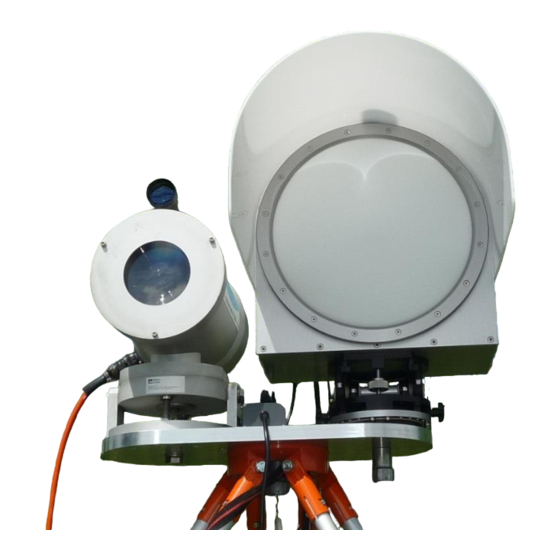
Figure 14: Setup of a combined Optical/Microwave Scintillometer (OMS) system with crossing beams. Tx: transmitters, Rx: receivers. 3.3.1 Mounting the Alignment Units Figure 15: No tools are needed to fasten the alignment units to the RPG-MWSC-160 transmitter/receiver. MWSC Installation & Maintenance +49 (0) 2225 99981 –... - Page 22 (Figure 5). The mounting on the double base plate is shown in Figure 17. Figure 18 shows how the height adaptors are attached to the LAS transmitter/receiver. Figure 16: Fasten center bolt to mount RPG-MWSC-160 units on a tripod (single configuration). Figure 17: Mounting the MWSC units in the double configuration.
-
Page 23: Mounting On Towers
RPG-MWSC-160 Installation & Maintenance Guid Guide Figure 18: Mounting the height adaptors for LAS transmitter and receiver. 3.3.2 Mounting on Towers With increasing path lengths, the scintillometers have to be mounted at higher observations heights (Figure 19, left). For example, a path length of 5000 m, requires an observation height above 40 meters to avoid saturation of the LAS signal (Figure 13). -
Page 24: Cable Connections And Power Up
The RPG-MWSC units provide a connector for a direct 12 V DC supply. Optionally, two AC power supplies are mounted on the back panel of each instrument. In both cases, the LAS transmitter and receiver are connected to the RPG-MWSC-160 units for power supply (exception: BLS2000 from Scintec). Make sure that the connecting power cables are plugged-in as labeled before the system is powered. -
Page 25: Alignment Of The Rpg-Mwsc-160 Units
“RX” port. The Ethernet cable can either be plugged into a local network or it can directly connect to the H-PC (peer-to-peer configuration) (for details refer to the RPG-MWSC-160 Instrument Manual). Figure 21: Setting up the fibre-optical cable for data transfer. - Page 26 (Figure 24). During long-term operations the user shall regularly check, if the screws are still tightly fixed. Figure 23: RPG-MWSC-160 alignment units allow adjustment of elevation (A) and azimuth (B) angle. The alignment process includes two steps: At first, the alignment telescopes (Figure 24) help to catch the transmitted signal by adjusting the receiver and the transmitter by sight.
- Page 27 RPG-MWSC-160 Installation & Maintenance Guid Guide In a second step, the received signal level is maximized by fine tuning the receiver pointing. When no transmitter signal is received, the displayed value is close to zero (Figure 26). If ‘1’ is displayed, the signal level is out of range. Only one axis shall be adjusted at a time.
-
Page 28: Appendix A (Instrument Dimensions)
RPG-MWSC-160 Installation & Maintenance Guid Guide Appendix A (Instrument Dimensions) Total weights: • Receiver: 12 kg (including weather station) • Transmitter: 10 kg MWSC Installation & Maintenance +49 (0) 2225 99981 – 0 RPG Radiometer Physics GmbH Werner-von-Siemens-Str. 4 www.radiometer-physics.de 53340 Meckenheim, Germany remotesensing-service@radiometer-physics.de...
Need help?
Do you have a question about the RPG-MWSC-160 and is the answer not in the manual?
Questions and answers