Page 3
�. Zero-export function via energy meter ����������� - 19 - 7.1 Multiple strings and parallel connection meters ����������� - 28 - 7.2 Use of zero-export function ������������������ - 38 - 7.3 Notes while using zero export function ������������ - 39 - 7.4 How to browse the load power of your PV grid-tieplant on monitoring platform? - 39 - �.
�. Introduction �.� Appearance Introduction On-grid Inverter can convert solar panel DC power into AC power which can directly input to the grid. Its appearance is shown below.These models contain SUN-40K-G04, SUN-45K-G04, SUN-50K-G04. The following is collectively referred to as “inverter”.
�.� Parts list Please check the following table, to see whether all the parts are included in the package: Mounting stainless steel screws M4×12 Grid-tied PV String Inverter Wall mounting bracket x1 User manual DC+/DC- Plug connectors Stainless steel anti-collision including metal terminal bolt M6×60 User manual x1...
�.� Product handling requirements One people stand on both sides of the machine, holding two handles to lift the machine. transport �. Safety warnings and instructions Improper use may result in potential electric shock hazards or burns. This manual contains important instructions that should be followed during installation and maintenance.
Warning: Inverter adopts non-isolated topology structure, hence must insure DC input and AC output are electrical isolated before operating the inverter. Shock Hazard: Prohibit disassembling inverter case, there existing shock hazard, which may cause serious injury or death, please ask qualified person to repair. Shock Hazard: When PV module is exposed to sunlight, the output will generate DC voltage.
�. Operation Interface �.� Interface View Normal Alarm Pic 3.1 Front panel display �.� Status Indicator There are four LED status indicator lights in the front panel of the inverter. Please see table 3.1 for details. Indicator status Explanation Inverter detects DC input off...
�.� Buttons There are four keys in the front panel of the Inverter(from left to right): Esc, Up, Down and Enter keys. The keypad is used for: Scrolling through the displayed options (the Up and Down keys); ● Access to modify the adjustable settings (the Esc and Enter keys). ●...
�. Product installation 4.1 Select installa�on loca�on To select a location for the inverter, the following criteria should be considered: WARNING: Risk of fire Do not install the inverter in areas containing highly flammable materials or gases. ● Do not install the inverter in potentially explosive atmospheres. ●...
Page 11
Install on a wall or strong structure capable of bearing the weight. ● Install vertically with a maximum incline of +15°. If the mounted inverter is tilted to an angle ● greater than the maximum noted, heat dissipation can be inhibited, and may result in less than expected output power.
≥500mm ≥500mm Pic 4.3 Installation Gap �.� Inverter Installation The inverter is designed according to the wall mounted type installation, please use the wall mounted (the brick wall of the expansion bolt) when installing. Anchoring Mounting bracket Stainless steel screws Inverter Pic 4.4 Inverter Installation - 09 -...
Page 13
Procedure shows below: 1. Locate on the appropriate wall according to the bolt position on the mounting bracket, then mark the hole.On the brick wall, the installation must be suitable for the expansion bolt installation. Pic 4.5 Inverter hanging plate installation 2.
5 Electrical Connec�on �.� PV Module Selection: When selecting proper PV modules, please be sure to consider below parameters: 1) Open circuit Voltage (Voc) of PV modules not exceeds max. PV array open circuit voltage of inverter. 2) Open circuit Voltage (Voc) of PV modules should be higher than min. start voltage. 3) The PV modules used to connected to this inverter shall be Class A rating certified according to lEC 61730.
Page 15
Safety Hint: Please use approved DC cable for PV system. Cross section(mm ) Cable type Range Recommended value Industry generic PV cable 2.5-4.0 2.5(12AWG) (model: PV1-F) (12~10AWG) Table 5.1 DC Cable Specifications The steps to assemble the DC connectors are listed as follows: a) Strip off...
Max. DC input current should be 20A. if exceeds, it may damage the inverter and it is not covered by Deye warranty. �.� AC input terminal connection Do not close the DC switch after the DC terminal is connected.Connect the AC terminal to the AC side of the inverter, the AC side is equipped with Three phase AC terminals that can be conveniently connected.
Page 17
L3 PE L1 L2 Pic 5.7 AC input connection Warning: Be sure that AC power source is disconnected before attempting to wire it to the unit. 1. Before making Grid port connection, be sure to turn off AC baeaker or disconnector first. 2.
�.� The connection of the ground line Good grounding is good for resisting surge voltage shock and improving EMI performance.There- fore, before connecting AC, DC and communication cables, you need to ground the cable firstly. For a single system, just ground the PE cable. For multiple machine systems, all PE cables of the inverter need to be connected to the same grounding copper platoon to ensure the equipoten- tial connection.
In order to protect the inverter AC connection, it is recommended to install a circuit breaker to prevent overcurrent. See table 5.3 below. Rated output Rated output Current for protection Inverter voltage(V) current(A) device(A) SUN-40K-G04 220/230 60.6/58A SUN-45K-G04 220/230 68.2/65.2A SUN-50K-G04 220/230 75.8/72.5A Table 5.3 Recommended current protector specifications...
�.� Installation of datalogger When installing the WiFi stick, tear off the sealing strip on the inverter. Insert the datalogger into the interface and fix it with a screw. The configuration of the datalogger needs to be performed after various electrical connections have been completed and the inverter DC power on.
�.� Start up the inverter When starting up the three phase string inverter, should fellow steps below: 1. Starting switch on the AC breaker. 2. Turn on the DC switch of the photovoltaic module, and if the panel provides sufficient starting voltage and power, the inverter will start.
7. Zero-export func�on via energy meter There're two kinds of energy meters for this series inverter. First type is Eastron SDM630-Mod- bus V2 which is able to measure the Max. 100A current directly. More details please refer to Pic 7.1 & 7.2. For the Eastron SDM630 MCT 40mA, it needs external CT to measure the current. The CT power range is from 5A-2000A.
Page 23
� � � � � � � � L� L� L� Eastron L� L� L� Gird Load (�,�,�,�) (�,�,�,�) B A G RS ��� � � � � RS 485 B RS 485 A Eastron SDM630-Modbus V2 Inverter Solar Panel array AC Breaker RS 485 Male...
Page 24
� � � � � � � � L� L� L� Eastron L� L� L� Gird Load (�,�,�,�) (�,�,�,�) B A G RS ��� � � � � RS 485 B RS 485 A Eastron SDM630-Modbus V2 Inverter Solar Panel array AC Breaker RS 485 Male...
�.� Multiple strings and parallel connection meters This application is that when the string inverters work in parallel, there is only one power grid and one load, and only one meter can be connected to prevent reverse current, so only this many-to-one anti-reverse current connection can be connected.
Page 32
Name Description Range AVG: Average power of three phase is zero exported. MIN: Phase with minimum load power is zero Exp_Mode AVG/MIN exported, while the other two phase may be in purchase mode. CT ratio of power grid side meter when extern CT is CT_Ratio 1-1000 applied.
Page 33
� � � � � � � � L� L� L� Eastron L� L� L� Gird Load (�,�,�,�) (�,�,�,�) B A G RS ��� � � � � RS 485 B RS 485 A Eastron SDM630-Modbus V2 Master(Mst) Grid L1 L2 L3 N RS���...
Page 34
� � � � � � � � L� L� L� Eastron L� L� L� Gird Load (�,�,�,�) (�,�,�,�) B A G RS ��� � � � � RS 485 B RS 485 A Eastron SDM630-Modbus V2 Generator Master(Mst) L1 L2 L3 N RS���...
�.� Use of zero-export function When the connection is completed, the following steps should be refered to use this function: 1. Turn on the AC switch. 2. Turn on the DC switch, waiting for the inverter's LCD is turned on. 3.
�.� Notes while using zero export function For your safety and the operation of limiter function of the inverter, we put forward the following suggestions and precautions: Safety Hint: Under zero export mode we strongly recommend that the two PV arrays are formed by the same number of PV panels of the same size, which will make the inverter more responsive to limit the power.
Page 43
And then choose your system type as “Self-consumption” Edit Plant Cancel Done Address : Basic Info YongJiang Road, Beilum,NingBo, ������, China System Info Yield Info Coordinates : Owner Info Longitude ��� �� ��.�� Latitude �� �� ��.�� ” ” Time Zone : Creation Time : ����/��/��...
8. General Opera�on During normal operation, the LCD shows the current status of the inverter, including the current power, total generation, a bar chart of power operation and inverter ID,etc. Press the Up key and the Down key to see the current DC voltage, DC current, AC voltage, AC current,inverter radiator temperature,software version number and Wifi...
Page 45
Ac�veP Q-Mode VRated Q(%) ReactP Exp_Mode Fun- ISO CT_Ra�o 0 Fun RCD FeedIn SelfCheck Shunt ShuntQTY Island Generator Meter G.CT Setup G.MFR Limiter G.FeedIn Running param G.Pout Feed-in V1-V12 G.Cap DC1-Wind OFF/ON MPPT Num DC2-Wind OFF/ON WindTurbine Cancel OF-Derate UF-Uprate WGRa WGraStr LVRT...
Page 46
*Note: These parameters will be avaiable after the meter is Brazil connected successfully. Otherwise, it won't show. EN50549-1-PL EN50549-1 Attention: For running param detail on the LCD display, please IEC61727 refer to the official Deye website https://www.deyeinverter.com CUSTOM VDE_4105 VDE_0126 Spain CEI_0-21 G98_G99...
�.� The initial interface From the initial interface, you can check PV power, PV voltage, grid voltage, inverter ID, model and other infomation. Power: Power: State: Standby State: Com.Error Pic 8.2 The initial interface Press UP or Down, you can check inverter DC voltage, DC current, AC voltage, AC current and inverter temperature.
ImpEp: Daily energy purchased from grid; Total: Total energy purchased from grid. ImpEp: 0.00KWh Total : 0.00KWh Pic 8.11 Electrical energy ExpEp: Daily energy sold to grid; Total: Total energy sold to grid. ExpEp: 0.00KWh Total : 0.00KWh Pic 8.12 Electrical energy �.�...
Page 49
�.�.� ON/OFF setting ON / OFF << Turn ON << Setup Turn OFF Turn ON Turn OFF << Cancel << Cancel Pic 8.15 ON/OFF setting When the inverter is turned off, it stops working immediately, and go to standby mode and then will go to self-test program again.
�.� System param setting System Param includes time set, language set, display set and factory reset. Time Set << Display Set Language Set Factory Reset << Factory Reset Set Restore << Pic 8.17 System Param 20200522 OK English << Polski 08:11:21 Cancel Pic 8.18 Time Bright Delay...
�.� Protect Param setting Warning: Engineer Only. We will set the param depends on the safety requirements, so customers don't need to reset it. The password is same as 8.4 Running param PassWord GridStanderd << Advanced Back << Pic 8.24 Password Braszil EN50549-1 EN50549-1-PL <<...
Page 52
OverVolt OverVolt Point 240.0V << Delay 1000ms << OverVolt OverVolt Point 240.0V << Delay 1000ms << OverVolt OverVolt Point 240.0V << Delay 1000ms << UnderVolt UnderVolt Point 235.0V << Delay 1000ms << UnderVolt UnderVolt Point 235.0V << Delay 1000ms << UnderVolt UnderVolt Point...
9. Repair and Maintenance String type inverter doesn’t need regular maintenance. However,debris or dust will affect heat sink’s thermal performance. It is better to clean it with a soft brush. If the surface is too dirty and affect the reading of LCD and LED lamp, you can use wet cloth to clean it up. High Temperature Hazard: When the device is running, the local temperature is too high and the touch can cause burns.
Check the solar panel output connection. Failure in reading memory (EEPROM). Restart the inverter if the Read the memory error F�� fault still exists, contact your installer or Deye service. Failure in writing memory (EEPROM). Restart the inverter if the Write the memory error F��...
Page 56
�. Check if the inverter FW version is suitable for the hardware. �. Restart the inverter, if the error still exists, please contact your installer or Deye service. DC leakage flow fault Hardly appear the code. Never ever happened so far.
Page 57
�. Check AC current sensor and its circuit. AC over current(one cycle) �. Restart the inverter, if the fault still exists, contact your installer or Deye service. DC over current Hardly appear the code. Never ever happened so far. Check the AC voltage protection setting. And Check if the AC AC Line W,U over voltage cable is too thin.Check the voltage difference between LCD and...
Page 58
DC busbar voltage is too low then showing F��, maybe Loss of driver or need update firmware. �. Restart the inverter, if the fault still exists, contact your installer or Deye service. AC reverse irrigation AC reverse irrigation. AC grid U over current Hardly appear the code.
· Low Voltage Directive 2014/35/EU (LVD) · Restriction of the use of certain hazardous substances 2011/65/EU(RoHS) NINGBO DEYE INVERTER TECHNOLOGY CO., LTD. confirms herewith that the products described in this document are in compliance with the fundamental requirements and other relevant provisions of the above mentioned directives.
Page 61
Product: 
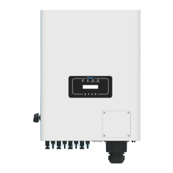
Grid-connected PV Inverter Models: SUN-50K-G04;SUN-45K-G04;SUN-40K-G04; Name and address of the manufacturer: Ningbo Deye Inverter Technology Co., Ltd. No. 26 South YongJiang Road, Daqi, Beilun, NingBo, China This declaration of conformity is issued under the sole responsibility of the manufacturer. Also this product is under manufacturer’s warranty.
Need help?
Do you have a question about the SUN-40K-G04 and is the answer not in the manual?
Questions and answers