Table of Contents
Advertisement
Quick Links
www.ti.com
EVM User's Guide: THVD4411EVM
THVD4411 Evaluation Module
Description
The THVD4411EVM allows for quick prototyping of
TI's RS-485 and RS-232 multiprotocol transceiver
(THVD4411). The EVM allows for half and full duplex
RS-485 operational modes as well as 1T1R RS-232
communication. The THVD4411EVM can be powered
by a single supply from 3V to 5.5V or can have
a separate logic supply that allows control of the
transceiver by controllers operating as low as 1.8V.
Multiple speeds are allowed through the use of the
slew rate control pin and the ability to use integrated
terminations in RS-485 mode.
Get Started
1. Order the EVM from ti.com (THVD4411EVM)
2. See the latest product information and data sheet
for
THVD4411
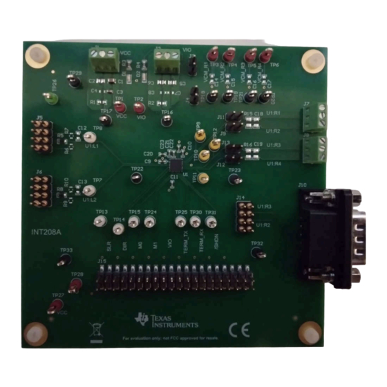
THVD4431EVM (Top Side)
SLLU380 – MARCH 2024
Submit Document Feedback
Features
•
THVD4411RGE pre-installed onto evaluation
module
•
Eight bulk power-supply decoupling capacitor pads
for VCC and VIO connections
•
0603 resistor pads available to create resistive link
between GND and EARTH connections for both
VIO and VCC terminals
•
Terminal and header pin access to RS-232 and
RS-485 bus signals
•
D-sub or header connections for RS-232 signals
Applications
•
Industrial PC
•
Factory automation and control
•
HVAC systems
•
Building automation
•
Point-of-sale terminals
•
Grid infrastructure
•
Industrial transport
Copyright © 2024 Texas Instruments Incorporated
THVD4411EVM (Bottom Side)
THVD4411 Evaluation Module
Description
1
Advertisement
Table of Contents

Subscribe to Our Youtube Channel
Related Manuals for Texas Instruments THVD4411


Summary of Contents for Texas Instruments THVD4411
- Page 1 • THVD4411RGE pre-installed onto evaluation TI's RS-485 and RS-232 multiprotocol transceiver module (THVD4411). The EVM allows for half and full duplex • Eight bulk power-supply decoupling capacitor pads RS-485 operational modes as well as 1T1R RS-232 for VCC and VIO connections communication.
-
Page 2: Kit Contents
(1) THVD4411EVM with the THVD4411RGE pre-installed ready to operate directly out of box. 1.3 Specification Refer to THVD4411 data sheet (SLLSFR9) for most to up to date specification for device. A selection of common usage ranges for devices considered in the construction of the board are shown below. - Page 3 Single Supply Operation (Logic Supply Equals Main Voltage Supply) The THVD4411 Transceiver in the RGE package from TI has an additional logic supply pin, VIO. This is used to power the internal digital logic circuits inside of the device. In single supply operation mode for the THVD4421RGE, the VIO pin must be shorted to VCC by shorting the header pins of J3, so that the digital circuits are properly powered.
-
Page 4: Board Setup And Operation
The mode pins along with the TERM_TX and TERM_RX pins must be configured before communication starts as opposed to changing during communication for proper operation. All the various modes of the THVD4411 share the use of the logic pins (denoted with the prefix “L”) and the bus pins (denoted with the prefix “R”). - Page 5 Figure 2-2. U1:LX Header Pinout The function of each individual L pin depends on the mode in which the THVD4411 is being operated in. Bus pins are the higher voltage tolerant pins for use with RS-485 or RS-232 depending on chosen operation mode.
- Page 6 Half duplex operation is a very common implementation of RS-485 and entered when the mode is 10 for M1 and M0 respectively. In half duplex mode, the receive and transmit bus facing pins (denoted R# on the THVD4411) are shared by the transceiver, allowing for asynchronous bi-directional communication on two wires with the trade-off being that the bus can only have 1 driver at a time and a device cannot receive and transmit data simultaneously.
- Page 7 Shunt rows 2 and 3 to connect R2 and RS-232 bus signal jumper 4x2 Header R3 pins to J10 for RS-232 THVD4411 control signal Access control pins for THVD4411 and 2x20 Header access VIO and GND connections available 2.4 Resistor Information Table 2-4.
-
Page 8: Led Information
Possibly not light up for VIO < 3.3V 2.7 IC Information Table 2-7. Debug IC ID Function Package Comment Installed? THVD4411 – RS-485 and RS-232 Comes pre-installed with THVD4411RGE multiprotocol transceiver THVD4411 Evaluation Module SLLU380 – MARCH 2024 Submit Document Feedback Copyright © 2024 Texas Instruments Incorporated... -
Page 9: Test Points
2.9 Assembly Instructions No Additional Assembly Required. Component pads are available for modification if desired by end user. 2.10 Best Practices For best results, refer to THVD4411 data sheet (SLLSFR9) for proper part operation. SLLU380 – MARCH 2024 THVD4411 Evaluation Module Submit Document Feedback Copyright ©... - Page 10 Figure 3-1. Power Supply Schematic THVD4411EVM - All Components Shown Figure 3-2. Power Supply Schematic THVD4411EVM - Default Configuration Shown Figure 3-3. Main IC Schematic THVD4411EVM - All Components Shown THVD4411 Evaluation Module SLLU380 – MARCH 2024 Submit Document Feedback Copyright © 2024 Texas Instruments Incorporated...
- Page 11 Hardware Design Files Figure 3-4. Main IC Schematic THVD4411EVM - Default Configuration Shown SLLU380 – MARCH 2024 THVD4411 Evaluation Module Submit Document Feedback Copyright © 2024 Texas Instruments Incorporated...
-
Page 12: Pcb Layouts
Hardware Design Files www.ti.com 3.2 PCB Layouts Figure 3-5. Top Layer of PCB Layout - THVD4411EVM Figure 3-6. Bottom Layer of PCB Layout - THVD4411EVM THVD4411 Evaluation Module SLLU380 – MARCH 2024 Submit Document Feedback Copyright © 2024 Texas Instruments Incorporated... - Page 13 Hardware Design Files Figure 3-7. 3D Rendering of Top Layer - THVD4411EVM Figure 3-8. 3D Rendering of Bottom Layer - THVD4411EVM SLLU380 – MARCH 2024 THVD4411 Evaluation Module Submit Document Feedback Copyright © 2024 Texas Instruments Incorporated...
-
Page 14: Bill Of Materials (Bom)
5014 Keystone Electronics TP16, TP17, TP18, TP19, TP20, TP21, TP22, TP23, 5011 Keystone Electronics TP29, TP32, TP33 TP26 5126 Keystone Electronics THVD4411RGE Texas Instruments THVD4411 Evaluation Module SLLU380 – MARCH 2024 Submit Document Feedback Copyright © 2024 Texas Instruments Incorporated... - Page 15 No issues known. 4.2 Trademarks All trademarks are the property of their respective owners. 5 Related Documentation 5.1 Supplemental Content THVD4411 data sheet (SLLSFR9) SLLU380 – MARCH 2024 THVD4411 Evaluation Module Submit Document Feedback Copyright © 2024 Texas Instruments Incorporated...
- Page 16 STANDARD TERMS FOR EVALUATION MODULES Delivery: TI delivers TI evaluation boards, kits, or modules, including any accompanying demonstration software, components, and/or documentation which may be provided together or separately (collectively, an “EVM” or “EVMs”) to the User (“User”) in accordance with the terms set forth herein.
- Page 17 www.ti.com Regulatory Notices: 3.1 United States 3.1.1 Notice applicable to EVMs not FCC-Approved: FCC NOTICE: This kit is designed to allow product developers to evaluate electronic components, circuitry, or software associated with the kit to determine whether to incorporate such items in a finished product and software developers to write software applications for use with the end product.
- Page 18 www.ti.com Concernant les EVMs avec antennes détachables Conformément à la réglementation d'Industrie Canada, le présent émetteur radio peut fonctionner avec une antenne d'un type et d'un gain maximal (ou inférieur) approuvé pour l'émetteur par Industrie Canada. Dans le but de réduire les risques de brouillage radioélectrique à...
- Page 19 www.ti.com EVM Use Restrictions and Warnings: 4.1 EVMS ARE NOT FOR USE IN FUNCTIONAL SAFETY AND/OR SAFETY CRITICAL EVALUATIONS, INCLUDING BUT NOT LIMITED TO EVALUATIONS OF LIFE SUPPORT APPLICATIONS. 4.2 User must read and apply the user guide and other available documentation provided by TI regarding the EVM prior to handling or using the EVM, including without limitation any warning or restriction notices.
- Page 20 Notwithstanding the foregoing, any judgment may be enforced in any United States or foreign court, and TI may seek injunctive relief in any United States or foreign court. Mailing Address: Texas Instruments, Post Office Box 655303, Dallas, Texas 75265 Copyright © 2023, Texas Instruments Incorporated...
- Page 21 TI products. TI’s provision of these resources does not expand or otherwise alter TI’s applicable warranties or warranty disclaimers for TI products. TI objects to and rejects any additional or different terms you may have proposed. IMPORTANT NOTICE Mailing Address: Texas Instruments, Post Office Box 655303, Dallas, Texas 75265 Copyright © 2024, Texas Instruments Incorporated...
Need help?
Do you have a question about the THVD4411 and is the answer not in the manual?
Questions and answers