Advertisement
Quick Links
www.ti.com
EVM User's Guide: THVD24X2VEVM
THVD24X2VEVM User's Guide
Parker Dodson
Description
This EVM user's guide for the THVD24X2VEVM provides a quick method to evaluate TI's THVD24X2V family
of full duplex transceivers in a SOIC package. This EVM user's guide describes the THVD24X2VEVM and the
intended use of the evaluation module.
Features
•
Ready to use out-of-box with THVD2452VDR preinstalled
•
Two 10-µF and two 47-µF decoupling capacitors installed on VCC to GND and GND to EARTH connections
•
Resistor pad available to create resistive link between GND and EARTH connections
•
Common-mode voltage connection points to test device with multiple common-mode voltages
SLLU368 – APRIL 2023
Submit Document Feedback
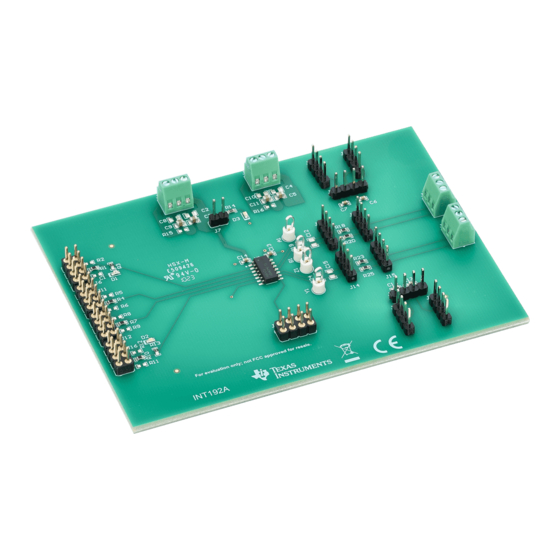
Figure 1-1. THVD24X2VEVM Top View
Copyright © 2023 Texas Instruments Incorporated
Description
THVD24X2VEVM User's Guide
1
Advertisement

Subscribe to Our Youtube Channel
Related Manuals for Texas Instruments THVD24X2VEVM


Summary of Contents for Texas Instruments THVD24X2VEVM
- Page 1 Description This EVM user’s guide for the THVD24X2VEVM provides a quick method to evaluate TI’s THVD24X2V family of full duplex transceivers in a SOIC package. This EVM user’s guide describes the THVD24X2VEVM and the intended use of the evaluation module.
- Page 2 1 Evaluation Module Overview 1.1 Kit Contents The THVD24X2VEVM is ready to operate directly out-of-box with a THVD2452VDR transceiver in a D package installed at site U1 on the board. In addition to the preinstalled THVD2452VDR, the following tables describe each pad on the THVD24X2VEVM board and which components are already installed by default.
- Page 3 Evaluation Module Overview Table 1-2 describes the pads on the THVD24X2VEVM board where resistors are installed by default and pads where additional resistors can be added. Table 1-2. Resistor Pads on the THVD24X2VEVM Board Pad Name Function Package Comment Installed? 0-Ω...
- Page 4 100-nF, 25-V decoupling capacitor 0805 “Z” line common-mode decoupling capacitor The THVD24X2VEVM has three LEDs preinstalled on pads D1, D2, and D3. These LEDs are in a non-standard package. Table 1-4 provides the location and the function of each LED.
- Page 5 VIO power input VCC power input 2.2 Operating the THVD24X2VEVM in Default Setup Out-of-the-box the EVM, when powered, can operate the THVD2452V as a full duplex RS-485 transceiver. The device pins are separated into four distinct groups: single-ended communication pins, differential communication pins, power pins, and control pins.
- Page 6 Leave floating for single supply applications, attach digital supply if dual operation is used Attach VCC to J2 Shunt for single supply Open for dual supply THVD24X2VEVM User's Guide SLLU368 – APRIL 2023 Submit Document Feedback Copyright © 2023 Texas Instruments Incorporated...
- Page 7 Operating the EVM 2.3 Operating the THVD24X2VEVM With Modifications 2.3.1 Single-ended Bus Modification Operational Modes There are a few options for modifying the single ended data and control signals on this EVM. Jumpers J6, J11, J12, and J16 all contain pads that are blank by default. For D, DE, and /RE signals there are 0603-sized pads for either pullup or pulldown resistors to have a default logic on these pins with the added benefit of still being able to external signals to this pin.
- Page 8 Hardware Design Files www.ti.com 3 Hardware Design Files 3.1 Schematics Figure 3-1. THVD24X2VEVM - Schematic (No Variant) Figure 3-2. THVD24X2VEVM - Schematic (Default Variant) THVD24X2VEVM User's Guide SLLU368 – APRIL 2023 Submit Document Feedback Copyright © 2023 Texas Instruments Incorporated...
-
Page 9: Pcb Layouts
Hardware Design Files 3.2 PCB Layouts Figure 3-3. THVD24X2VEVM - Layout (Top View) SLLU368 – APRIL 2023 THVD24X2VEVM User's Guide Submit Document Feedback Copyright © 2023 Texas Instruments Incorporated... - Page 10 Hardware Design Files www.ti.com Figure 3-4. THVD24X2VEVM - Layout (Bottom View) THVD24X2VEVM User's Guide SLLU368 – APRIL 2023 Submit Document Feedback Copyright © 2023 Texas Instruments Incorporated...
-
Page 11: Bill Of Materials (Bom)
Hardware Design Files 3.3 Bill of Materials (BOM) Table 3-1. Bill of Materials for the THVD24X2VEVM Package Designator Quantity Value Description Part Number Manufacturer Reference White Test Point, Multipurpose, White, A1, B1, Y1, Z1 Multipurpose 5012 Keystone Testpoint CAP, CERM, 10 uF, 6.3 V, +/-... -
Page 12: Additional Information
Additional Information www.ti.com Table 3-1. Bill of Materials for the THVD24X2VEVM (continued) Package Designator Quantity Value Description Part Number Manufacturer Reference R5, R9, R12 RES, 50, 2%, 3.9 W, 0603 0603 RCP0603W50R0GEB Vishay-Dale R17, R21, R22, RES, 15 k, 5%, 0.1 W, 0603... - Page 13 STANDARD TERMS FOR EVALUATION MODULES Delivery: TI delivers TI evaluation boards, kits, or modules, including any accompanying demonstration software, components, and/or documentation which may be provided together or separately (collectively, an “EVM” or “EVMs”) to the User (“User”) in accordance with the terms set forth herein.
- Page 14 www.ti.com Regulatory Notices: 3.1 United States 3.1.1 Notice applicable to EVMs not FCC-Approved: FCC NOTICE: This kit is designed to allow product developers to evaluate electronic components, circuitry, or software associated with the kit to determine whether to incorporate such items in a finished product and software developers to write software applications for use with the end product.
- Page 15 www.ti.com Concernant les EVMs avec antennes détachables Conformément à la réglementation d'Industrie Canada, le présent émetteur radio peut fonctionner avec une antenne d'un type et d'un gain maximal (ou inférieur) approuvé pour l'émetteur par Industrie Canada. Dans le but de réduire les risques de brouillage radioélectrique à...
- Page 16 www.ti.com EVM Use Restrictions and Warnings: 4.1 EVMS ARE NOT FOR USE IN FUNCTIONAL SAFETY AND/OR SAFETY CRITICAL EVALUATIONS, INCLUDING BUT NOT LIMITED TO EVALUATIONS OF LIFE SUPPORT APPLICATIONS. 4.2 User must read and apply the user guide and other available documentation provided by TI regarding the EVM prior to handling or using the EVM, including without limitation any warning or restriction notices.
- Page 17 Notwithstanding the foregoing, any judgment may be enforced in any United States or foreign court, and TI may seek injunctive relief in any United States or foreign court. Mailing Address: Texas Instruments, Post Office Box 655303, Dallas, Texas 75265 Copyright © 2023, Texas Instruments Incorporated...
-
Page 18: Important Notice
TI products. TI’s provision of these resources does not expand or otherwise alter TI’s applicable warranties or warranty disclaimers for TI products. TI objects to and rejects any additional or different terms you may have proposed. IMPORTANT NOTICE Mailing Address: Texas Instruments, Post Office Box 655303, Dallas, Texas 75265 Copyright © 2023, Texas Instruments Incorporated...
Need help?
Do you have a question about the THVD24X2VEVM and is the answer not in the manual?
Questions and answers