Page 1
Range Road 6022, 6026, 6032 Sawmill Owner’s Manual WARNING: Read carefully and understand all ASSEMBLY AND OPERATION INSTRUCTIONS before operating. Failure to follow the safety rules and other basic safety precautions may result in serious personal injury. Item # 
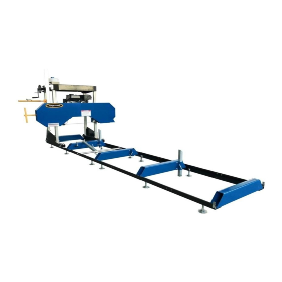
RR6022A/B, RR6026AW, RR6032AW/BW...
INTENDED USE The Range Road Sawmill is portable and versatile which makes it a great tool for any lumber project. It has the capabilities of sawing logs up to 22”, 26”, 32” in diameter, 8” thick and a cutting length of 125”.
Always check for damaged or worn parts before using the saw mill. Broken parts will affect the saw mill operation. Replace or repair damaged or worn parts immediately. • Do not exceed the saw mill load capacity. Range Road Enterprises Ltd Box 5 Site 9 RR1 Lacombe, AB T4L 2N1 www.range-road.ca...
Set up and use only on a flat and level surface. Area must be well ventilated. Wear ANSI-approved safety goggles, heavy-duty work gloves, and dust mask/respirator during set up. Range Road Enterprises Ltd Box 5 Site 9 RR1 Lacombe, AB T4L 2N1...
This is a poison you cannot see or smell. NEVER use gas engines indoors EVEN IF doors and window are open. Only use OUTSIDE and far away from windows, doors and vents. Range Road Enterprises Ltd Box 5 Site 9 RR1 Lacombe, AB T4L 2N1 www.range-road.ca...
Page 6
6. Use only accessories that are recommended by Range Road for your model. Accessories that may be suitable for one piece of equipment may become hazardous when used on another piece of equipment.
• Wear approved safety goggles, heavy-duty gloves, and a dust mask/respirator during service. • Maintain all labels on the saw mill. These show important information. If unreadable, missing or damaged, contact Range Road for a replacement. • Have the equipment serviced by a qualified repair person using only OEM replacement parts. This will ensure that the safety of the saw mill is maintained.
The operator should contact local agencies for laws or regulations relating to fire prevention requirements. Assembly Read all of the safety precautions and warnings in this manual before setting up or using this product. Range Road Enterprises Ltd Box 5 Site 9 RR1 Lacombe, AB T4L 2N1 www.range-road.ca...
Page 9
Place 2 guide rails on the floor and install 2 or 3 leveling feet in the large round holes on the bottom of each rail. Place the 2 rails on their leveling feet parallel to each other Range Road Enterprises Ltd Box 5 Site 9 RR1 Lacombe, AB T4L 2N1 www.range-road.ca...
Page 10
4 holes on each side, this rail will eventually be the center of the rails and it has a side pocket on it. Range Road Enterprises Ltd Box 5 Site 9 RR1 Lacombe, AB T4L 2N1 www.range-road.ca...
Page 11
Make sure the two rails are level to one another. Do cross measurements now to make sure the rails are square to each other. Both lengths should be the same. Range Road Enterprises Ltd Box 5 Site 9 RR1 Lacombe, AB T4L 2N1...
Page 12
Mount and tighten center log support cross tube. Put the leveling feet on next 2 rails and put them in position at the center log support cross tube. Range Road Enterprises Ltd Box 5 Site 9 RR1 Lacombe, AB T4L 2N1...
Page 13
When you have the rails level with the log support cross tube use clamps to hold the outer rails together. Level one rail, then level the 2nd rail from it Range Road Enterprises Ltd Box 5 Site 9 RR1 Lacombe, AB T4L 2N1...
Page 14
Cross measure new rails and adjust as required. Re check levelness and cross measurements. Now that the track is assembled, mill head assembly is the next step Range Road Enterprises Ltd Box 5 Site 9 RR1 Lacombe, AB T4L 2N1...
Page 15
Place the top frame on the floor and put the 2 galvanized corner posts in and finger tighten all 4 bolts. Range Road Enterprises Ltd Box 5 Site 9 RR1 Lacombe, AB T4L 2N1 www.range-road.ca...
Page 16
Lift and rotate the top frame so it is right side up and position it at head unit. Put the back cover in position. Range Road Enterprises Ltd Box 5 Site 9 RR1 Lacombe, AB T4L 2N1 www.range-road.ca...
Page 17
Install the front guard with the Range Road logo. On the water tank side install the scale bracket with the bolts. Range Road Enterprises Ltd Box 5 Site 9 RR1 Lacombe, AB T4L 2N1 www.range-road.ca...
Page 18
Place spacers and pulleys on bottom bolts, pulley circlips face the spacers, put nuts and washers on but do not tighten up. Take out bolt for water tank and mount water tank. Range Road Enterprises Ltd Box 5 Site 9 RR1 Lacombe, AB T4L 2N1...
Page 19
Range Road Enterprises Ltd Box 5 Site 9 RR1 Lacombe, AB T4L 2N1 www.range-road.ca...
Page 20
Run threaded rod through the angle bracket on each side of the head unit and tighten the cables up. Lift complete head so the feet can be installed next step. Range Road Enterprises Ltd Box 5 Site 9 RR1 Lacombe, AB T4L 2N1...
Page 21
Mount left and right roller assemblies onto the galvanized tubes, snug bolts up but do not tighten them. Install carriage stabilizer. Range Road Enterprises Ltd Box 5 Site 9 RR1 Lacombe, AB T4L 2N1 www.range-road.ca...
Page 22
Position head unit over track and line rollers up so that the track sits in the roller groove, set head unit onto tracks. Tighten all 8 bolts on roller frames and 8 on top frame of head unit. Range Road Enterprises Ltd Box 5 Site 9 RR1 Lacombe, AB T4L 2N1...
Page 23
Measure distance from the blade log support on each side to double check that head unit is level. Install roller stops at all 4 frame corners. Range Road Enterprises Ltd Box 5 Site 9 RR1 Lacombe, AB T4L 2N1 www.range-road.ca...
Page 24
Mount control handle on right hand post, making sure throttle cable is not twisted, tighten 2 bolts. Mount Scale bar, the metal spacer sits behind the bar at base Remove these 2 bolts and metal spacer. where the 2 bolts secure it. Range Road Enterprises Ltd Box 5 Site 9 RR1 Lacombe, AB T4L 2N1 www.range-road.ca...
Page 25
Install log holder into frame rails, There are multiple frame holes for mounting, choose the one that works best for your application. Range Road Enterprises Ltd Box 5 Site 9 RR1 Lacombe, AB T4L 2N1...
Page 26
Blade tension should also be double checked – looking for about 32 ft/lbs if using a torque wrench on the big nut on the orange T-handle. When firing up the machine for the first time, run at an idle, verify there are no fuel leaks. Range Road Enterprises Ltd Box 5 Site 9 RR1 Lacombe, AB T4L 2N1...
Page 27
Run the unit up to full rpm and verify blade is running smooth, the units moves up and down easily and engine is running properly. There are different adjustment procedures and troubleshooting listed below in this manual. Range Road Enterprises Ltd Box 5 Site 9 RR1 Lacombe, AB T4L 2N1...
Page 28
Bolt 99 with a wrench. Then tighten Nut 98C after adjustment. Continue making small adjustments until the Blade stays centered. AFTER any adjustment, tighten Bolts 96A and 96B and nuts 98A and 98B. Range Road Enterprises Ltd Box 5 Site 9 RR1 Lacombe, AB T4L 2N1...
The log should be positioned so that the force of cutting holds it against supports. Log supports need to be lower than the thickness of the board being cut to avoid blade damage. Range Road Enterprises Ltd Box 5 Site 9 RR1 Lacombe, AB T4L 2N1 www.range-road.ca...
Page 31
13. The cut direction must be as shown below. If the log is cut from the other direction, the saw blade will push the log away from the supports and may cause the log to become unstable. Range Road Enterprises Ltd Box 5 Site 9 RR1 Lacombe, AB T4L 2N1 www.range-road.ca...
18. Move the Saw Head slowly along the track and against the log to make the cut. NOTE: Repeated adjustments will need to be made during cutting. Range Road Enterprises Ltd Box 5 Site 9 RR1 Lacombe, AB T4L 2N1...
3. Apply a thin coat of rust preventive oil to all uncoated metal parts. 4. Cover and store in dry, well-ventilated area out of reach of children. Range Road Enterprises Ltd Box 5 Site 9 RR1 Lacombe, AB T4L 2N1...
Tension blade properly Blade cuts Too much blade speed and/ Reduce blade speed and rate of feed. feed rate. rough. Blade is too coarse. Use recommended blade only. Range Road Enterprises Ltd Box 5 Site 9 RR1 Lacombe, AB T4L 2N1 www.range-road.ca...
Page 35
Remove stray branches that prevent proper positioning. Clean debris off blade. Follow all safety precautions whenever diagnosing or servicing the equipment or engine. Range Road Enterprises Ltd Box 5 Site 9 RR1 Lacombe, AB T4L 2N1 www.range-road.ca...
Page 36
Range Road Enterprises Ltd Box 5 Site 9 RR1 Lacombe, AB T4L 2N1 www.range-road.ca...
Page 37
Range Road Enterprises Ltd Box 5 Site 9 RR1 Lacombe, AB T4L 2N1 www.range-road.ca...
Note: Some parts are listed and shown for illustration purposed only, and are not available individually as replacement parts. WARRANTY One-year limited warranty For technical questions, please visit www.range-road.ca www.range-road.com Range Road Enterprises Ltd Box 5 Site 9 RR1 Lacombe, AB T4L 2N1 www.range-road.ca...