Table of Contents
Advertisement
Quick Links
WARNING:
Read carefully and understand all ASSEMBLY AND OPERATION INSTRUCTIONS before
operating. Failure to follow the safety rules and other basic safety precautions may result in
serious personal injury.
Range Road Enterprises Ltd
Box 5 Site 9 RR1
Lacombe, AB T4L 2N1
www.range-road.ca
Range Road RR6036AW
Sawmill Owner's Manual
Item #
RR6036AW
Advertisement
Table of Contents

Related Manuals for Range Road RR6036AW


Summary of Contents for Range Road RR6036AW
- Page 1 Range Road RR6036AW Sawmill Owner’s Manual WARNING: Read carefully and understand all ASSEMBLY AND OPERATION INSTRUCTIONS before operating. Failure to follow the safety rules and other basic safety precautions may result in serious personal injury. Item # RR6036AW Range Road Enterprises Ltd...
-
Page 2: Intended Use
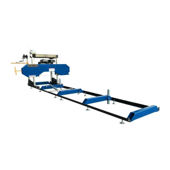
INTENDED USE The Range Road Saw Mill is portable and versatile which makes it a great tool for any lumber project. It has the capabilities of sawing logs up to 36” in diameter, 8” thick and a cutting length of 125”. -
Page 3: Work Area
It is also a good idea to back off the blade tension when not in use, helps to preserve belt and blade life. Inspect it for good working condition prior to storage and before re-use. Range Road Enterprises Ltd Box 5 Site 9 RR1 Lacombe, AB T4L 2N1 www.range-road.ca... -
Page 4: Important Safety Information
Engine exhaust contains carbon monoxide. This is a poison you cannot see or smell. NEVER use gas engines indoors EVEN IF doors and window are open. Only use OUTSIDE and far away from windows, doors and vents. Range Road Enterprises Ltd Box 5 Site 9 RR1 Lacombe, AB T4L 2N1 www.range-road.ca... - Page 5 Caution is necessary when near the engine’s magneto or recoil starter. Use only accessories that are recommended by Range Road for your model. Accessories that may be suitable for one piece of equipment may become hazardous when used on another piece of equipment.
- Page 6 • Maintain all labels on the sawmill. These show important information. If unreadable, missing or damaged, contact Range Road for a replacement. • Have the equipment serviced by a qualified repair person using only OEM replacement parts. This will ensure that the safety of the sawmill is maintained.
- Page 7 Open the package and carefully remove the individual parts and boxes from the crate and organize on the floor. Leave the large head unit resting in the crate. Locate all the rail pieces and lay out on the floor. Range Road Enterprises Ltd Box 5 Site 9 RR1 Lacombe, AB T4L 2N1...
- Page 8 The angle iron rails will now be mounted to the square tubing frame – don’t tighten the hardware yet as the rails may need to be adjusted when the two track sections are joined together. Range Road Enterprises Ltd Box 5 Site 9 RR1 Lacombe, AB T4L 2N1 www.range-road.ca...
- Page 9 The rail sections can now be joined together using the flat plate on the outside and the “L” bracket on the inside. The loose rails can now be pushed together so there is no space between the rail ends. Tighten rails down to sqaure tubing. Range Road Enterprises Ltd Box 5 Site 9 RR1 Lacombe, AB T4L 2N1...
- Page 10 The end Brackets can also be installed at this time. The bunks can now be mounted to the “L” brackets and the two sides of the track will be joined together. Range Road Enterprises Ltd Box 5 Site 9 RR1 Lacombe, AB T4L 2N1 www.range-road.ca...
- Page 11 When attaching the bunks to the “L” brackets, keep these bolts loose for now. The sawmill head (once assembled) will be used to set the width of the track. Range Road Enterprises Ltd Box 5 Site 9 RR1 Lacombe, AB T4L 2N1...
- Page 12 Then do cross measurements now to make sure the rails are square to each other. Both measurements should be within ¼” of each other. Leave the bunks loose. Next step will be to move onto the head assembly. Range Road Enterprises Ltd Box 5 Site 9 RR1 Lacombe, AB T4L 2N1 www.range-road.ca...
- Page 13 These will also have the pulleys mounted to them. Install upright so the holes where the pulleys were located are at the top. Install with the holes facing out to the sides. Range Road Enterprises Ltd Box 5 Site 9 RR1 Lacombe, AB T4L 2N1...
- Page 14 The rear uprights will now be inserted into the top bracket assembly. Insert the uprights so the two holes line up with the holes in the top bracket assembly – loosely install bolts. Range Road Enterprises Ltd Box 5 Site 9 RR1 Lacombe, AB T4L 2N1 www.range-road.ca...
- Page 15 The top bracket will line up with the front posts that were installed earlier. Before installing any bolts, the front header with the Range Road logo and the silver “L” bracket for the measuring gauge will also be installed and all held together with the main top bracket assembly.
- Page 16 On the water tank side install the scale bracket with the bolts. Place spacers and pulleys on bottom bolts, pulley circlips face the spacers, put nuts and washers on but do not tighten up yet. Range Road Enterprises Ltd Box 5 Site 9 RR1 Lacombe, AB T4L 2N1...
- Page 17 Take out bolt for water tank and mount water tank holder. The lift cables will now be installed, left and right side. Range Road Enterprises Ltd Box 5 Site 9 RR1 Lacombe, AB T4L 2N1 www.range-road.ca...
- Page 18 Find the two stubs on the inside of the top plate behind the pulley arm, place a cable loop over a stub and run cable around pulleys and down to head. Range Road Enterprises Ltd Box 5 Site 9 RR1 Lacombe, AB T4L 2N1 www.range-road.ca...
- Page 19 Hook the power lift motor up to the battery and lift the head assembly up about 8”. (this picture shows a unit with a manual crank, but the procedure is the same) Range Road Enterprises Ltd Box 5 Site 9 RR1 Lacombe, AB T4L 2N1 www.range-road.ca...
- Page 20 Mount left and right roller assemblies onto the galvanized tubes, snug bolts up but do not tighten them. Install carriage stabilizer. Range Road Enterprises Ltd Box 5 Site 9 RR1 Lacombe, AB T4L 2N1 www.range-road.ca...
- Page 21 Install the measuring gauge onto the head assembly. Range Road Enterprises Ltd Box 5 Site 9 RR1 Lacombe, AB T4L 2N1 www.range-road.ca...
- Page 22 Keep in mind that the head will be sitting on the track which will raise the unit about 5” or so. The lower 8 bolts for the feet and the upper 8 bolts for the top bracket assembly can be tightened. Range Road Enterprises Ltd Box 5 Site 9 RR1 Lacombe, AB T4L 2N1 www.range-road.ca...
- Page 23 Once the squareness of the track has been checked and the width has been set, the bunks can now be tightened to the “L” brackets which will lock everything in place. Run the mill up and down the track again to make sure it runs smoothly. Adjust if necessary. Range Road Enterprises Ltd Box 5 Site 9 RR1 Lacombe, AB T4L 2N1...
- Page 24 Install log dog into frame rails, there are multiple frame holes for mounting, choose the one that works best for your size of log. Range Road Enterprises Ltd Box 5 Site 9 RR1 Lacombe, AB T4L 2N1...
- Page 25 Install T-handles into track cross supports to hold the log supports in place, adjust silver pin on head unit so that the blade is protected if the head is lower than the log support. Range Road Enterprises Ltd Box 5 Site 9 RR1 Lacombe, AB T4L 2N1 www.range-road.ca...
- Page 26 Note that the fuel tank sits on the bracket and does not bolt into place – hardware is provided but holes need to be drilled into the bracket if you wish to have the tank bolted down. Range Road Enterprises Ltd Box 5 Site 9 RR1 Lacombe, AB T4L 2N1 www.range-road.ca...
- Page 27 The red cable will go to the top stud on the starter solenoid. Black cable can go to any bolt on the engine block – we used one of the bolts that holds the key assembly to the engine. Range Road Enterprises Ltd Box 5 Site 9 RR1 Lacombe, AB T4L 2N1 www.range-road.ca...
- Page 28 Installation for Range Road RR5195 Electric Power Head for 36” Sawmill Knock roll pin out of crank handle and remove. Unbolt circular plate. (2- 12mm bolts) Remove bolt on Lovejoy connection of new electric motor. Back out set screws and take off lock nuts on square housing of new electric motor. Make set screws flush on inside of housing.
- Page 29 Align the holes on the sha with the old crank handle. Once aligned, slide on new power head and install bolt. Evenly screw in set screws and tighten with lock nuts. Range Road Enterprises Ltd Box 5 Site 9 RR1 Lacombe, AB T4L 2N1 www.range-road.ca...
- Page 30 Hook up positive and negative wires. Range Road Enterprises Ltd Box 5 Site 9 RR1 Lacombe, AB T4L 2N1 www.range-road.ca...
- Page 31 Run the unit up to full rpm and verify blade is running smooth, the units moves up and down easily and engine is running properly. There are different adjustment procedures and troubleshooting listed below in this manual. Powerhead kit installation instructions are listed at the end of this manual. Range Road Enterprises Ltd Box 5 Site 9 RR1 Lacombe, AB T4L 2N1 www.range-road.ca...
- Page 32 Range Road Enterprises Ltd Box 5 Site 9 RR1 Lacombe, AB T4L 2N1 www.range-road.ca...
- Page 33 Bolt 99 with a wrench. Then tighten Nut 98C after adjustment. Continue making small adjustments until the Blade stays centered. AFTER any adjustment, tighten Bolts 96A and 96B and nuts 98A and 98B. Range Road Enterprises Ltd Box 5 Site 9 RR1 Lacombe, AB T4L 2N1...
-
Page 34: Blade Adjustment
Blade Adjustment NOTE: Use a tape measure to verify distances. Range Road Enterprises Ltd Box 5 Site 9 RR1 Lacombe, AB T4L 2N1 www.range-road.ca... -
Page 35: Engine Operation
D) Read the Equipment Operation section that follows. Start and operate the engine according to the provided engine manual. Replacement engine operating instructions can be obtained from the engine manufacturer Range Road Enterprises Ltd Box 5 Site 9 RR1 Lacombe, AB T4L 2N1... - Page 36 NOTE: Make sure the Log Clamp Assembly (20) does NOT interfere with the Saw Blade when sawing. The Log Clamp Assembly (20) should be lower than the Saw Blade at all times. Range Road Enterprises Ltd Box 5 Site 9 RR1 Lacombe, AB T4L 2N1 www.range-road.ca...
- Page 37 15. Start and operate the engine according to the provided engine manual. 16. Adjust the Throttle to bring the Blade up to speed. The Locking Ring can be turned to lock the throttle in place. Range Road Enterprises Ltd Box 5 Site 9 RR1 Lacombe, AB T4L 2N1 www.range-road.ca...
- Page 38 20. Trim off the rounded sides of the lumber. 21. After the log is squared-off, boards or posts can be cut. Range Road Enterprises Ltd Box 5 Site 9 RR1 Lacombe, AB T4L 2N1...
- Page 39 4. Cover and store in dry, well-ventilated area out of reach of children. 5. For cold weather operation, store the equipment in a cool dry area to prevent condensation and premature wear. Range Road Enterprises Ltd Box 5 Site 9 RR1 Lacombe, AB T4L 2N1...
-
Page 40: Equipment Troubleshooting
Remove stray branches that prevent Teeth filled with debris. proper positioning. 4. Clean debris off blade. Follow all safety precautions whenever diagnosing or servicing the equipment or engine. Range Road Enterprises Ltd Box 5 Site 9 RR1 Lacombe, AB T4L 2N1 www.range-road.ca... - Page 41 Range Road Enterprises Ltd Box 5 Site 9 RR1 Lacombe, AB T4L 2N1 www.range-road.ca...
- Page 42 Range Road Enterprises Ltd Box 5 Site 9 RR1 Lacombe, AB T4L 2N1 www.range-road.ca...
- Page 43 Range Road Enterprises Ltd Box 5 Site 9 RR1 Lacombe, AB T4L 2N1 www.range-road.ca...
- Page 44 Range Road Enterprises Ltd Box 5 Site 9 RR1 Lacombe, AB T4L 2N1 www.range-road.ca...
- Page 45 Range Road Enterprises Ltd Box 5 Site 9 RR1 Lacombe, AB T4L 2N1 www.range-road.ca...
-
Page 46: Please Read The Following Carefully
Note: Some parts are listed and shown for illustration purposed only, and are not available individually as replacement parts. WARRANTY One-year limited warranty For technical questions, please visit www.range-road.ca www.range-road.com Range Road Enterprises Ltd Box 5 Site 9 RR1 Lacombe, AB T4L 2N1 www.range-road.ca...
Need help?
Do you have a question about the RR6036AW and is the answer not in the manual?
Questions and answers