Table of Contents
Advertisement
Quick Links
WARNING:
Read carefully and understand all ASSEMBLY AND OPERATION
INSTRUCTIONS before operating. Failure to follow the safety rules and other basic
safety precautions may result in serious personal injury.
Range Road Enterprises Ltd
Box 5 Site 9 RR1
Lacombe, AB T4L 2N1
www.range-road.ca
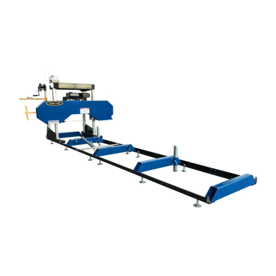
Range Road Range Road 6026AW
Saw Mill
Owner's Manual
Item #
Advertisement
Table of Contents

Related Manuals for Range Road 6026AW


Summary of Contents for Range Road 6026AW
- Page 1 Range Road Range Road 6026AW Saw Mill Owner’s Manual WARNING: Read carefully and understand all ASSEMBLY AND OPERATION INSTRUCTIONS before operating. Failure to follow the safety rules and other basic safety precautions may result in serious personal injury. Item #...
-
Page 2: Intended Use
INTENDED USE The Range Road Saw Mill is portable and versatile which makes it a great tool for any lumber project. It has the capabilities of sawing logs up to 22”, 26” or 29” in diameter, 7” thick and a cutting length of 125”. -
Page 3: Technical Specifications
It must be understood by the operator that common sense and caution are factors which cannot be built into this product, but must be supplied by the operator. SAVE THESE INSTRUCTIONS Range Road Enterprises Ltd Box 5 Site 9 RR1 Lacombe, AB T4L 2N1 www.range-road.ca... -
Page 4: Work Area
Always check for damaged or worn parts before using the saw mill. Broken parts will affect the saw mill operation. Replace or repair damaged or worn parts immediately. Do not exceed the saw mill load capacity. Range Road Enterprises Ltd Box 5 Site 9 RR1 Lacombe, AB T4L 2N1 www.range-road.ca... -
Page 5: Important Safety Information
Set up and use only on a flat and level surface. Area must be well ventilated. Wear ANSI-approved safety goggles, heavy-duty work gloves, and dust mask/respirator during set up. Range Road Enterprises Ltd Box 5 Site 9 RR1 Lacombe, AB T4L 2N1... -
Page 6: Carbon Monoxide Hazard
1. Keep children and bystanders away from the equipment, especially during operation. 2. Do not leave the equipment unattended when it is running. Turn off the equipment (and remove safety keys, if available) before leaving the work area. Range Road Enterprises Ltd Box 5 Site 9 RR1 Lacombe, AB T4L 2N1... - Page 7 Caution is necessary when near the engine’s magneto or recoil starter. 6. Use only accessories that are recommended by Range Road for your model. Accessories that may be suitable for one piece of equipment may become hazardous when used on another piece of equipment.
-
Page 8: Service Precautions
Wear approved safety goggles, heavy-duty gloves, and a dust mask/respirator during service. Maintain all labels on the saw mill. These show important information. If unreadable, missing or damaged, contact Range Road for a replacement. Have the equipment serviced by a qualified repair person using only OEM replacement parts. -
Page 9: Specifications
If you do not feel completely comfortable assembling it, please have a qualified technician assemble it. Note: For any additional information regarding the saw mill parts, refer to Assembly Diagram near the end of this manual. Range Road Enterprises Ltd Box 5 Site 9 RR1 Lacombe, AB T4L 2N1... - Page 10 Place the 2 rails on their leveling feet parallel to each other, the measurement from center to center will be roughly: RR6022 A/B …..RR6026 AW 845mm (33 1/4”) RR6032A/B …..Range Road Enterprises Ltd Box 5 Site 9 RR1 Lacombe, AB T4L 2N1...
- Page 11 4 holes on each side, this rail will eventually be the center of the rails and it has a side pocket on it. Range Road Enterprises Ltd Box 5 Site 9 RR1 Lacombe, AB T4L 2N1 www.range-road.ca...
- Page 12 - RR6022 A/B …..- RR6026 AW 845mm (33 1/4”) - RR6032A/B …..7) Do cross measurements now to make sure the rails are square to each other. Range Road Enterprises Ltd Box 5 Site 9 RR1 Lacombe, AB T4L 2N1 www.range-road.ca...
- Page 13 9) Mount and tighten center log support cross tube. 10) Put the leveling feet on next 2 rails and put them in position at the center log support cross tube. Range Road Enterprises Ltd Box 5 Site 9 RR1 Lacombe, AB T4L 2N1...
- Page 14 11) When you have the rails level with the log support cross tube use clamps to hold the outer rails together. 12) Level one rail, then level the 2nd rail from it Range Road Enterprises Ltd Box 5 Site 9 RR1 Lacombe, AB T4L 2N1 www.range-road.ca...
- Page 15 14) Cross measure new rails and adjust 15) When rails are square and level tighten 8 bolts in log support cross tube, mount the center log support cross tube and tighten it. Range Road Enterprises Ltd Box 5 Site 9 RR1 Lacombe, AB T4L 2N1...
- Page 16 17) Take the 2 galvanized square posts with the pulleys on them and place them into the head unit square tubes, remove the bolts and pulleys, pay attention to where the pulley spacers go, place these to the side. Range Road Enterprises Ltd Box 5 Site 9 RR1 Lacombe, AB T4L 2N1...
- Page 17 18) Place the top frame on the floor and put the 2 galvanized corner posts in and finger tighten all 4 bolts. 19) Lift and rotate the top frame so it is right side up and position it at head unit. Range Road Enterprises Ltd Box 5 Site 9 RR1 Lacombe, AB T4L 2N1 www.range-road.ca...
- Page 18 20) Put the back cover in position and put both bolts in. 21) On the water tank side install the scale bracket with the bolts. Range Road Enterprises Ltd Box 5 Site 9 RR1 Lacombe, AB T4L 2N1 www.range-road.ca...
- Page 19 22) Place spacers and pulleys on bottom bolts, pulley circlips face the spacers, put nuts and washers on but do not tighten up. 23) Take out bolt for water tank and mount water tank. Range Road Enterprises Ltd Box 5 Site 9 RR1 Lacombe, AB T4L 2N1...
- Page 20 Range Road Enterprises Ltd Box 5 Site 9 RR1 Lacombe, AB T4L 2N1...
- Page 21 25) Run threaded rod through the angle bracket on each side of the head unit and tighten the cables up. 26) Lift complete head. Range Road Enterprises Ltd Box 5 Site 9 RR1 Lacombe, AB T4L 2N1 www.range-road.ca...
- Page 22 27) Mount left and right roller assemblies onto the galvanized tubes, snug bolts up but do not tighten them. 28) Install carriage stabilizer. Range Road Enterprises Ltd Box 5 Site 9 RR1 Lacombe, AB T4L 2N1 www.range-road.ca...
- Page 23 29) Position head unit over track and line rollers up so that the track sits in the roller groove, set head unit onto tracks. Range Road Enterprises Ltd Box 5 Site 9 RR1 Lacombe, AB T4L 2N1 www.range-road.ca...
- Page 24 Measure distance from the blade log support on each side to double check that head unit is level. 32) Install roller stops at all 4 frame corners. Range Road Enterprises Ltd Box 5 Site 9 RR1 Lacombe, AB T4L 2N1...
- Page 25 Mount Scale bar, the metal spacer sits behind the bar at base 34) Remove these 2 bolts and metal spacer. where the 2 bolts secure it. Range Road Enterprises Ltd Box 5 Site 9 RR1 Lacombe, AB T4L 2N1 www.range-road.ca...
- Page 26 36) Install log holder into frame rails, There are multiple frame holes for mounting, choose the one that works best for your application. Range Road Enterprises Ltd Box 5 Site 9 RR1 Lacombe, AB T4L 2N1...
- Page 27 37) Install T-handles into track cross supports to hold the log supports in place, adjust bracket on head unit so that the blade is protected if the head is lower than the log support. Range Road Enterprises Ltd Box 5 Site 9 RR1 Lacombe, AB T4L 2N1 www.range-road.ca...
- Page 28 Bolt 99 with a wrench. Then tighten Nut 98C after adjustment. Continue making small adjustments until the Blade stays centered. AFTER any adjustment, tighten Bolts 96A and 96B and nuts 98A and 98B. Range Road Enterprises Ltd Box 5 Site 9 RR1 Lacombe, AB T4L 2N1 www.range-road.ca...
-
Page 29: Blade Adjustment
Blade Adjustment NOTE: Use a tape measure to verify distances. Range Road Enterprises Ltd Box 5 Site 9 RR1 Lacombe, AB T4L 2N1 www.range-road.ca... -
Page 30: Engine Operation
5. Cut branches off the log to be processed before sawing. 6. Do not cut logs containing foreign objects (nails, metal, etc.). This will cause Blade damage and could cause serious injury. Range Road Enterprises Ltd Box 5 Site 9 RR1 Lacombe, AB T4L 2N1... - Page 31 NOTE: Make sure the Log Clamp Assembly does NOT interfere with the Saw Blade when sawing. The Log Clamp Assembly should be lower than the Saw Blade at all times. Scale and Scale Pointer Range Road Enterprises Ltd Box 5 Site 9 RR1 Lacombe, AB T4L 2N1...
-
Page 32: Throttle Control
15. Start and operate the engine according to the provided engine manual. 16. Adjust the Throttle to bring the Blade up to speed. Throttle Control Range Road Enterprises Ltd Box 5 Site 9 RR1 Lacombe, AB T4L 2N1 www.range-road.ca... -
Page 33: Maintenance Procedures
1. Lubricate the Band Wheel Axles, Square and Round Posts with machine oil before each use. 2. Lubricate the Tension Handle with grease monthly or as needed. Range Road Enterprises Ltd Box 5 Site 9 RR1 Lacombe, AB T4L 2N1... -
Page 34: Equipment Troubleshooting
2. Use recommended blade only. Blade is 1. Cut is binding blade. 1. Decrease feed pressure. twisting. 2. Blade tension too high. 2. Decrease blade tension. Range Road Enterprises Ltd Box 5 Site 9 RR1 Lacombe, AB T4L 2N1 www.range-road.ca... -
Page 35: Parts List
4. Clean debris off blade. Follow all safety precautions whenever diagnosing or servicing the equipment or engine. Parts List not the correct picture not the correct picture Range Road Enterprises Ltd Box 5 Site 9 RR1 Lacombe, AB T4L 2N1 www.range-road.ca... - Page 36 Range Road Enterprises Ltd Box 5 Site 9 RR1 Lacombe, AB T4L 2N1 www.range-road.ca...
- Page 37 Range Road Enterprises Ltd Box 5 Site 9 RR1 Lacombe, AB T4L 2N1 www.range-road.ca...
- Page 38 Range Road Enterprises Ltd Box 5 Site 9 RR1 Lacombe, AB T4L 2N1 www.range-road.ca...
-
Page 39: Please Read The Following Carefully
Note: Some parts are listed and shown for illustration purposed only, and are not available individually as replacement parts. WARRANTY One-year limited warranty For technical questions, please visit www.range-road.ca www.range-road.com Range Road Enterprises Ltd Box 5 Site 9 RR1 Lacombe, AB T4L 2N1 www.range-road.ca...
Need help?
Do you have a question about the 6026AW and is the answer not in the manual?
Questions and answers