
Related Manuals for domi outdoor living LGMF1632


Summary of Contents for domi outdoor living LGMF1632
- Page 1 10'×20' LOUVERED PERGOLA ASSEMBLY MANUAL MODEL#: LGMF1632 Missing part? Damaged? Contact us via email at service@domioutdoorliving.com www.domioutdoorliving.com © Copyright 2022-2024 domi LLC. I All Rights Reserved.
- Page 2 -Maximum weight capacity is 1000 pounds. -If moderate to heavy snow is forecast, open the lovers to avoid snow accumulating.
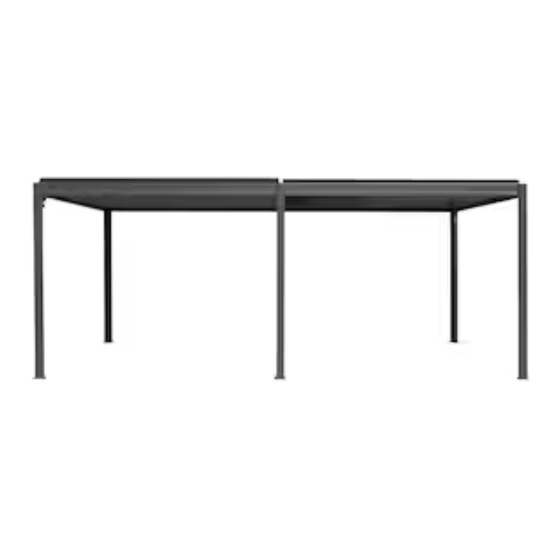
- Page 3 5976mm (235.28") 3009mm (118.46") 5976mm (235.28")
- Page 4 3035mm (119.49") 126mm (4.96") 3039mm (119.65") 116mm (4.57") 116mm (4.57")
- Page 5 Expansion Bolts 67mm(2.64 ) 35mm 1.38 If the deck is hard wood and the depth of it is over 3 inch If the ground is concreted and the depth you can use 5/16 in. ×4 in. of it is over 3 inch you can use expansion Structural Wood Screw to bolts to mount the pergola.
- Page 8 Step 1: Connect Part #A and Part #A1 with 3 Bolts 1# as shown. Repeat the above procedures to assemble the other 3 posts.
- Page 9 Step 2: Connect Part #Ab and Part #K with 4 Bolts 1# as shown. Repeat the above procedures to assemble another post.
- Page 10 Step 3: Insert part #A2, connect part #A3 with 2 bolts #1. Insert Repeat the above procedures to assemble the other 3 posts.
- Page 11 Inside View Inside View Outside View Step 4: Insert Part #F1 into Part #B1. Secure with 3 Bolts 1# as shown. Secure Part #F with 3 bolts #1 as shown in ④, ⑤. Repeat the above procedures to assemble another beam #1.
- Page 12 Step 5: Insert Part #G1 into the hole on Linkage Rod of Beam #B1. Secure with Nut 6# and gasket as shown. Repeat the above procedures to assemble another beam. Linkage Rod Linkage Rod...
- Page 13 Step 6: Insert Part# L into Part #B3 and Part #B4 with 4 Bolts 1# asshown. Repeat the above procedures to assemble another beam. Inside View...
- Page 14 Step 7: Use 8 Bolts# 1 to install Beam #B1 & #B3 with Post #A. Repeat the above procedures to assemble the other three sides. ATTENTION: Don't tighten the bolts before all bolts are in the correct place. Outside View Inside View...
- Page 15 Step 8: ①: Use 2 bolts #1 to secure part #A3 with 2 beams. ②: Use 2 bolts #3 to secure part #A4 with 2 beams. Repeat the above procedures to assemble other 3 corners. ATTENTION: Tighten all the bolts. Inside View...
- Page 16 Step 9: Use 2 bolts #3 to fix part #K2 with part #L; Use 2 bolts #3 to connect the assembled beam #B3 & #B4 with part #L. Repeat the above procedures to assemble another side. Inside View...
- Page 17 Middle Beam Assmbly Step 10: ②Install Part #K1 into Post #Ab as shown. ③Install 4 Bolts 2# to secure Assembled Beam (Part #B3 & B4) with Part #Ab. Repeat the above procedures to assemble another side. Inside View Inside View Outside View Insert Attention: Please align the holes before install the bolts.
- Page 18 Step 11: Install Part #M on the Part #Ab with 2 Bolts 1# as shown. Repeat the above procedures to assemble another side. Inside View...
- Page 19 ③ Step 12: Place the middle beam #B ( you can place in either direction). ③:Use 2 blots #1 to connect the middle beam #B with bracket #M. ②: Place part #D1 and part #N on the middle beam #B; Align the holes and fix with 6 bolts #1.
- Page 20 Rain-proof Strip Assembly: Step 13: Install Part #D on the inside of Part #B3 with 6 Bolts #3 as shown. Repeat the above procedures to assemble another side.
- Page 21 Linkage Rod Step 14: Linkage Rod ② Use 2 bolts #5, gaskets and nuts to ①Insert the connecting rod end of Part fix part #G with bracket #F. #G into Part #G1 and secure with 1 Nut 7# and gasket. Repeat the above procedures to assemble another side.
- Page 22 Step 15: Step 16: Place the roof panel, align the holes Insert part #H, and secure with and fix with bolts 9#. self-tapping bolts 8#. ※ If moderate to heavy snow is forecast, pls open the louvers to avoid snow accumulating.
- Page 23 Full Closed Full Open Half Open Step 17: Just shake the roller rod anytime you want let the sun in or block the sunray. (ATTENTION: Louvers can be opened and closed in cycles.) Please confirm the louvers can be fully closed for waterproofness.
Need help?
Do you have a question about the LGMF1632 and is the answer not in the manual?
Questions and answers