Advertisement
Quick Links
d mi
o u t d o o r l i v i n g
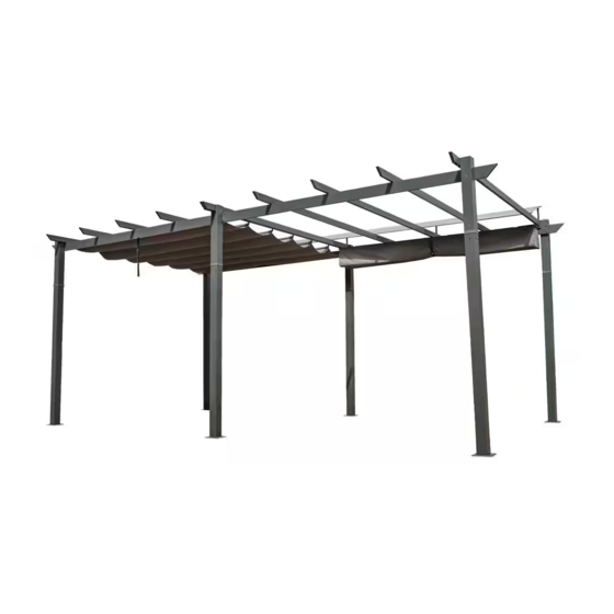
11' × 20' ALUMINUM
RETRACTABLE PERGOLA
ASSEMBLY MANUAL
MODEL#: LGMD1616
Missing part? Damaged? Contact us via email at
service@domioutdoorliving.com
www.domioutdoorliving.com
©
Copyright 2022-2024 Domi Outdoor Living LLC. All Rights Reserved.
Advertisement

Related Manuals for domi outdoor living LGMD1616


Summary of Contents for domi outdoor living LGMD1616
- Page 1 11' × 20' ALUMINUM RETRACTABLE PERGOLA ASSEMBLY MANUAL MODEL#: LGMD1616 Missing part? Damaged? Contact us via email at service@domioutdoorliving.com www.domioutdoorliving.com © Copyright 2022-2024 Domi Outdoor Living LLC. All Rights Reserved.
- Page 3 234.25" 3.54" 107.87" 107.87" 234.25" 25.98" 26.52" 26.52" 25.98" 3.54" 109" 116.14"...
- Page 5 Pole Pole Connector Pole Connector Pole Connector Beam Beam Beam Beam Beam Beam Beam Beam Crossbeam Crossbeam Crossbeam Crossbeam...
- Page 6 Crossbeam Crossbeam Crossbeam Crossbeam Crossbeam Crossbeam Crossbeam Crossbeam Canopy Bar Canopy Bar Canopy Bar Canopy Bar Canopy Bar Canopy Bar Canopy Bar Canopy Bar...
- Page 7 Canopy Bar Canopy Bar Solidifying Canopy Bar Plate Solidifying Canopy Joint Cover Joint Cover support stand Bracket Rope Pulley Hook Pulley Hook Pulley Hook Screw Cap Canopy Small canopy Anchor Stakes...
- Page 8 Step 1: ① Connect Part #A and Part #A1 (#A2, #A3) with 6 Bolts 1# as shown. ② Repeat the above procedures to assemble the other 3 posts.
- Page 9 Step 2: ① Connect Part #A and Part #B with 2 Bolts 1# as shown. ② Repeat the above procedures to assemble the other 5 Plates.
- Page 10 Step 3: ① Push #M into Part #C in the direction indicated by the arrow, then Connect Part #M and Part #C with 4 Bolts 1# as shown. ② Push M connected with C into C1 in the direction indicated by the arrow, then Connect Part #M and Part #C1 with 4 Bolts 1# as shown.
- Page 11 Step 4: ① Push #M into Part #C3 in the direction indicated by the arrow, then Connect Part #M and Part #C3 with 4 Bolts 1# as shown. ② Push M connected with C3 into C2 in the direction indicated by the arrow, then Connect Part #M and Part #C2 with 4 Bolts 1# as shown.
- Page 12 Step 5: ① Push #M into Part #D in the direction indicated by the arrow, then Connect Part #M and Part #D with 4 Bolts 1# as shown. ② Push M connected with D into D1 in the direction indicated by the arrow, then Connect Part #M and Part #D1 with 4 Bolts 1# as shown.
- Page 13 Step 6: ① Push #M into Part #D3 in the direction indicated by the arrow, then Connect Part #M and Part #D3 with 4 Bolts 1# as shown. ② Push M connected with D3 into D2 in the direction indicated by the arrow, then Connect Part #M and Part #D2 with 4 Bolts 1# as shown.
- Page 14 Step 7: ① Push #M1 into Part #C1 in the direction indicated by the arrow, then Connect Part #M1 and Part #C1 with 2 Bolts 1# as shown. ② Push M1 connected with C1 into C2 in the direction indicated by the arrow, then Connect Part #M1 and Part #C2 with 2 Bolts 1# as shown.
- Page 15 Step 8: ① Push #M1 into Part #D1 in the direction indicated by the arrow, then Connect Part #M1 and Part #D1 with 2 Bolts 1# as shown. ② Push M1 connected with D1 into D2 in the direction indicated by the arrow, then Connect Part #M1 and Part #D2 with 2 Bolts 1# as shown.
- Page 16 Step 9: ① Connect Part #A1(A2) and Part #D(D3/ C/ C3) with 4 Bolt #2 as shown. ② Put 4 plastic covers #T on the Bolt #2 as shown. Be aware of the connecting position of the poles and beams.
- Page 17 Step 10: ① Connect Part #A3 and the joint of Part #D1 & D2, Part #C1 & C2 with 4 Bolt 4# as shown. Be aware of the connecting position of the poles and beams. ② Place Part Q on Part A3 and Part C2/ C1/ D1/ D2. Secure with 4 Bolt #1 as shown.
- Page 18 Step 11: ① Slide 6 Pulleys #S2 into Part #E as shown. ② Connect Part #E and part #E1 with 4 Bolt #1 as shown. ③ Slide 6 Pulleys #S2 into Part #E2 as shown. ④ Connect Part #E2 and Part #E3 with 4 Bolt #1 as shown.
- Page 19 Step 12: ① Connect Part #E2(E3/ E/ E1) and Part A2(A1) with 4 Bolt #2 as shown. ② Put 4 plastic covers #T on the Bolt #2 as shown.
- Page 20 Step 13: ① Slide 6 Pulleys #S2 into Part #F as shown. ② Connect Part #F and part #F1 with 4 Bolt #1 as shown. ③ Slide 6 Pulleys #S2 into Part #F2 as shown. ④ Connect Part #F2 and Part #F3 with 4 Bolt #1 as shown.
- Page 21 Step 14: ① Connect the assembled crossbeam #F & F1, #F2 & F3 with 3 Bolts and Nuts #5 as shown.
- Page 22 Step 15: ① Place Part #F & F2 on Part #A3 as shown. ② Put Joint Cover #N on Part #F & Part #F2 as shown. ③ Connect Part #F & F2 and Part #A3 with 2 Bolt #3 as shown.
- Page 23 Step 16: ① Place Part #F1 & F3 on Part #A3 as shown. ② Put Joint Cover #N1 on Part #F1 & Part #F3 as shown. ③ Connect Part #F1 & F3 and Part #A3 with 2 Bolt #3 as shown. ④...
- Page 24 Step 17: ① First of all, slide 5 Pulleys #3 and 1 Pulley #S in turn into part G as shown in diagram. ② Connect part #G and part #G1 with 4 Bolts #1 as shown. Hang Part #R on Pulley #S. ③...
- Page 25 Step 18: ① Connect Part #G1 and Part #C2 C3 with Bolt #6 as shown. ② Connect Part #G1 and Part #C C1 with Bolt #6 as shown. Don’t need to assemble the opposite side in this step.
- Page 26 Step 19: ① Connect Part #H and Part #H1 with 4 Bolts 1# as shown. ② Repeat the above procedures to assemble the other 3 Crossbeams.
- Page 27 Step 20: ① Connect Part #H or Part #H1 to beam with 8 Bolts 6# as shown.
- Page 28 Step 21: ① Insert 4 sections (#K, K1, K2 ,K) into Small Canopy #U1. ② Insert part #J, J1, J2, J into Small Canopy #U1. ③ Use Canopy Support Stand #P to connect Part #J, J1, J2, J.
- Page 29 Step 22: ① Connect part #P and part #A1(A2) with 2 Bolt #1 as shown. ② Connect part #P and part #G with screw 1# and Bolts #6 as shown. ③ Connect part #P and part #F F2 with 1 Bolt #1 and 2 Bolts #6 as shown.
- Page 30 Step 23: ④ Use Bolts 3# to affix Part K with Cross Beam (Part #E or E2) as shown. ⑤ Use Bolts 3# to affix Part K1 with Cross Beam (Part #G) as shown. ⑥ Use Bolts 3# to affix Part K2 with Cross Beam (Part #F) as shown.
- Page 31 Step 24: ① Insert Part #J5, J3, J4, J5 into the pocket of top roof (Part U) and connect them as shown.
- Page 32 Step 25: ① Use 5 Bolts #5 to secure canopy Bar #J, J1, J2, J to the assembled Beam as shown.
- Page 33 Step 26: ① Connect Part #L and L1 through the hooks (Part #S1). ② Fix Part #L and #L1 with the hooks (Part S1) on both ends using Bolt 1#, then attach the strap of top roof to the hook for securing the tube.
- Page 34 Step 27: ① When the canopy is folded, hang the other end of string (Part R) into the hole on the inside of Beam (Part #D and Part #D1) to secure the top roof.
- Page 35 Step 28: ① Insert stakes (Part V) through the hole of stand plate (Part B) into the ground, to stabilize the tent. Only used temporary, they can not stand against the heavy wind.
- Page 36 Thanks for your purchase. At domi outdoor living, we believe in our products. That’s why we provide a 12-month warranty and friendly, casy-to-reach after-sales service. So if you have any questions about our product and assembly- ,please feel free to contact us.
Need help?
Do you have a question about the LGMD1616 and is the answer not in the manual?
Questions and answers