Table of Contents
Advertisement
Quick Links
Advertisement
Table of Contents

Related Manuals for UNIRAC EcoFoot2+


Summary of Contents for UNIRAC EcoFoot2+
- Page 1 INSTALLATION GUIDE 10-DEGREE BALLASTED RACKING SYSTEM UNIRAC Code-Compliant Installation Manual © 2022 by Unirac, Inc. All rights reserved. UNIRAC welcomes input concerning the accuracy and user-friendliness of this publication. Please write to publications@unirac.com. PUB2022OCT13...
-
Page 2: Table Of Contents
INSTALLATION GUIDE 10-DEGREE BALLASTED RACKING SYSTEM TABLE OF CONTENTS LEGAL NOTICES ..........1 INTRODUCTION . -
Page 3: Legal Notices
LEGAL NOTICES PAGE INSTALLATION GUIDE 10-DEGREE BALLASTED RACKING SYSTEM Legal Notices ©2017 Unirac®, Inc. Unirac® and EcoFoot2+® are registered trademarks of Unirac, Inc. -
Page 4: Introduction
10-DEGREE BALLASTED RACKING SYSTEM Field Support Contact Information Unirac proudly offers dedicated engineering expertise and superior customer support. For questions about the installation procedures or a specific application, please contact our Field Support Specialists at 866-488-6794 or FieldSupport@Unirac.com. Installer Responsibility The installer is solely responsible for: •... - Page 5 Unirac assumes no responsibility for any infringement of patents or other rights of third parties, which may result from use of modules. No license is granted by implication or under any patent or patent rights. The information in this manual is believed to be reliable, but does not constitute an expressed and/or implied warranty.
-
Page 6: Warnings And Safety
EcoFoot2+. Failure to follow the methods and procedures outlined in this guide may result in injury and/or damage to property. Carefully read this guide before starting any work. Store a copy of this guide on the job site at all times and contact Unirac with any installation questions related to EcoFoot2+. -
Page 7: General Application Notes
10-DEGREE BALLASTED RACKING SYSTEM EcoFoot2+ General Application Notes Site-Specific System Design: Unirac provides drafting services on all EcoFoot2+ projects. This service produces a site-specific design package with an Engineered Stamped Layout including detailed ballast plan and bill of materials. Roof Type: EcoFoot2+ is designed to mount photovoltaic modules to a range of roof surfaces, including: EPDM, TPO, PVC, Mineral Cap Sheet (a.k.a. Rolled Asphalt), Tar and Gravel. - Page 8 Class A roof with Type 1, Type 2, Type 3 module with a metal frame, Type 19, Type, 22, & Type 25. Type 29 and Type 30 modules whose encapsulation thickness matches the criteria for Type 3 modules are also an approved fire type. Contact Unirac with any questions about fire type compatibility.
-
Page 9: System Components
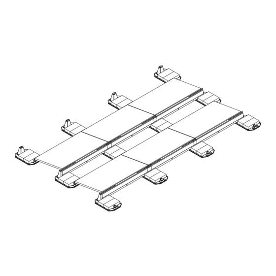
SYSTEM COMPONENTS PAGE INSTALLATION GUIDE 10-DEGREE BALLASTED RACKING SYSTEM EcoFoot2+ Core Components EcoFoot2+ Base Clamp-Upper Clamp-Lower Clevis Pin Deflector REVISIONS ITEM NO. PART NUMBER DESCRIPTION QTY. REV. DESCRIPTION DATE DRAWN BY ES11204-CP ECOFOOT 2+ MID SUPPORT UPPER BRACKET INITIAL RELEASE FOR PRODUCTION 12/17/2019 C.NO. - Page 10 SYSTEM INSTALLATION STEPS PAGE INSTALLATION GUIDE 10-DEGREE BALLASTED RACKING SYSTEM EcoFoot2+ Installation Instructions STEP 1: Chalk lines on roof denoting two outside edges of the EcoFoot2+® according to project drawing. Place EcoFoot2+® Bases (A) in position. TIPS • Ensure lines are square using 3-4-5 principle. •...
- Page 11 SYSTEM INSTALLATION STEPS PAGE INSTALLATION GUIDE 10-DEGREE BALLASTED RACKING SYSTEM STEP 3: Place module onto EcoFoot2+® Base (A). Using a 1/2" deep socket, Torque nuts (F). Space modules 1/2“ apart using the alignment marks on the Clamps. Torque Nuts (F) to 14 ft-lbs.
-
Page 12: System Installation Steps
SYSTEM INSTALLATION STEPS PAGE INSTALLATION GUIDE 10-DEGREE BALLASTED RACKING SYSTEM STEP 4: Place Ballast (not included) as required per PE Certified Ballast Plan provided. NOTE; In freeze/thaw environments, use concrete block with minimum compressive strength of 3,000psi (ref ASTM C1491-03 Standard Specifications for Concrete Roof Pavers). - Page 13 SYSTEM INSTALLATION STEPS PAGE INSTALLATION GUIDE 10-DEGREE BALLASTED RACKING SYSTEM STEP 6: Route, connect, and secure conductors. TIP: Wire clips attached to the module flange (not included) can be used to dress conductors in a row of modules. Integrated snap features in the Base can be used to dress conductors bridging rows.
- Page 14 SYSTEM INSTALLATION STEPS PAGE INSTALLATION GUIDE 10-DEGREE BALLASTED RACKING SYSTEM STEP 9: FINAL CHECK Check all fasteners to ensure that the torque values are correct and that the modules are properly positioned. ...
-
Page 15: Mid Support Installation
10-DEGREE BALLASTED RACKING SYSTEM MID SUPPORT KIT INSTALLATION The Mid Support Kit is a non-standard item and only used in heavy load conditions or with light-duty panels. The design team at Unirac will indicate use when required. INSTALLING LOWER MID-SUPPORT Locate module center point +/-1”... - Page 16 MID SUPPORT INSTALLATION PAGE INSTALLATION GUIDE 10-DEGREE BALLASTED RACKING SYSTEM INSTALLING UPPER MID-SUPPORT Locate module center point +/-1” using PV module cell lines. Slide the Lower Mid-Support slots onto Pull outwards to sit flat on the roof. module frame. Ensure the Mid Support positioned flat on the roof. Typical view of Mid supports after installation...
-
Page 17: Module Removal
MODULE REMOVAL PAGE INSTALLATION GUIDE 10-DEGREE BALLASTED RACKING SYSTEM Module Removal CAUTION • Module removal may disrupt the bonding path and could introduce the risk of electric shock. • See Grounding and Bonding Paths section to determine when module removal may disrupt the bonding path. •... -
Page 18: Roof Attachment With Strut
ROOF ATTACHMENT WITH STRUT INSTALLATION GUIDE PAGE 10-DEGREE BALLASTED RACKING SYSTEM INSTALLATION OF ROOF ATTACHMENT WITH STRUT TOOLS REQUIRED 1/2" Deep Socket 9/16" Deep Socket 1/2" Box End Wrench Calibrated Torque Wrench Power Drill with 3/8" Drill Bit Torque fasteners to 14 ft-lbs. Overview of Attachment System COMPONENTS EcoFoot Roof to Strut Hardware Kit... - Page 19 ROOF ATTACHMENT WITH STRUT INSTALLATION GUIDE PAGE 10-DEGREE BALLASTED RACKING SYSTEM ATTACHMENT WITH STRUT Strut runs North/South under PV modules, near the center of the module, placed as indicated on array layout. Strut does not connect to EcoFoot2 Bases. Strut is attached to Roof Attachment, low or south edge of PV modules and Wind Deflector.
- Page 20 ROOF ATTACHMENT WITH STRUT INSTALLATION GUIDE PAGE 10-DEGREE BALLASTED RACKING SYSTEM STEP 3: STEP 4: STEP 5: Place Roof Attachment within 1.5”- 4” from Slide Strut away and install Roof Attachment per Slide Strut back into position over Roof Attachment. attachment-side edge of Strut, illustrated by Red manufacturer’s instructions.
- Page 21 ROOF ATTACHMENT WITH STRUT INSTALLATION GUIDE PAGE 10-DEGREE BALLASTED RACKING SYSTEM STEP 9: STEP 10: Using Strut Strap Components shown, attach North Place Bolt behind Wind Deflector and bottom of Strut Strap in Strut channel. Torque Bolt to 14 ft-lbs. row Strut Strap to Wind Deflector and Strut.
- Page 22 ROOF ATTACHMENT WITH STRUT INSTALLATION GUIDE PAGE 10-DEGREE BALLASTED RACKING SYSTEM NOTE: When using U-Anchor Roof Attachment, the short side of L-Bracket 2 butts to the short side of L-Bracket 1, as shown in step 13. If you are using OMG Roof Attachment, see guidelines below for correct installation of L-Bracket 2.
- Page 23 Note that EcoFoot5D ballast trays will not be installed where strut is located. FIELD SUPPORT CONTACT INFORMATION UNIRAC proudly offers dedicated engineering expertise and superior customer support. For questions about the installation procedures or a specific application, please visit our website: www.unirac.com.
-
Page 24: Grounding And Bonding Paths
Wind Deflector, or by drilling a ¼” ground hole into the Wind Deflector a minimum of ½” from any edge. One Ground Lug is required for every 400 modules connected within an array. Unirac recommends using #6 copper ground wire in conjunction with WEEB grounding devices such as the WEEB-LUG-6.7 or WEEB DSK516. Lugs are a single use component. -
Page 25: Code Compliance Notes
CODE COMPLIANCE NOTES SYSTEM CERTIFICATION PAGE 10-DEGREE BALLASTED RACKING SYSTEM UL2703 System Label: The label shown below is stamped into to the Wind Deflector (identified as component "E" in the installation guide). The Date Code A B C Y Z Z shown above will appear on production parts, defined as follows: •... -
Page 26: Mechanical Load Test
Please consult the PV module manufacturer's installation guide for more information. In addition to UL 2703 certification, Unirac performs internal testing beyond the requirements of certification tests in order to establish system functional limits, allowable loads, and factors of safety. These tests include functional system tests, and destructive load testing. - Page 27 MECHANICAL LOAD TEST SYSTEM CERTIFICATION PAGE 10-DEGREE BALLASTED RACKING SYSTEM Design Load without Mid Supports Design Load down with Mid Sup- Module Manufacturer Model / Series Area [sq ft] [psf] ports [psf] JA Solar JAM72S10-XXX/MR 21.6 16.7 up / 27.2 down 51.3 JKMXXXP-60 17.62...
- Page 28 MECHANICAL LOAD TEST SYSTEM CERTIFICATION PAGE 10-DEGREE BALLASTED RACKING SYSTEM Design Load without Mid Supports Design Load down with Mid Sup- Module Manufacturer Model / Series Area [sq ft] [psf] ports [psf] TSM-XXX PA05.08 17.64 30 up / 30 down Trina TSM-XXXDE14A(II) 20.93...
-
Page 29: Compatible Modules
• Please see EcoFoot2+ information at unirac.com to ensure the exact solar module selected is approved for use with EcoFoot2+ • Listed models can be used to achieve a Class A fire system rating, for low slope applications, when modules fire typed 1, 2, 3 with a metal frame, 19, 22, 25, and modules typed 29 or 30...
Need help?
Do you have a question about the EcoFoot2+ and is the answer not in the manual?
Questions and answers
is this compatible to hyundai HIS-SxxxGI?