Table of Contents
Advertisement
Quick Links
Advertisement
Table of Contents

Related Manuals for UNIRAC ULA


Summary of Contents for UNIRAC ULA
- Page 1 INSTALLATION GUIDE PLANNING AND ASSEMBLY INSTALLATION MANUAL UNIRAC Code-Compliant Installation Manual © 2021 by Unirac, Inc. All rights reserved. PUB2022NOV17 UNIRAC welcomes input concerning the accuracy and user-friendliness of this publication. Please write to publications@unirac.com.
-
Page 2: Table Of Contents
Complying with all local or national building codes, including any that may supersede this manual. • Ensuring that UNIRAC and other products are appropriate for the particular installations and installation environment. • Ensuring safe installation of all electrical aspects of the PV array. -
Page 3: System Components
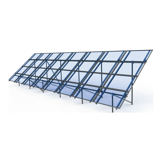
PLANNING AND ASSEMBLY INSTALLATION GUIDE PAGE INSTALLATION MANUAL IMAGE-2-FRONT CAP ULA COMPONENTS IMAGE-1-LANDSCAPE ASSY IMAGE-3-REAR CAP Components and quantities specific to your installations are listed on your quotation. IMAGE-4-SLIDER Note: Incidental materials such as temporary bracing or gravel may be necessary. - Page 4 ASSEMBLY INSTALLATION GUIDE PAGE INSTALLATION MANUAL ULA PORTRAIT ARRAY Portrait arrays utilize the same components as landscape arrays. IMAGE-1-PORTAIT ASSY MATERIAL SPECIFICATIONS Rails, caps, sliders, rail brackets, cross braces, bottom mounting clips, and top mounting clamps: 6105-T5 aluminum extrusion; caps are welded.
- Page 5 SYSTEM COMPONENTS PLANNING AND ASSEMBLY INSTALLATION GUIDE PAGE INSTALLATION MANUAL MODULE MOUNTING COMPONENTS S.NO. DESCRIPTION PART NUMBER SM ENDCLAMP B CLR AL 302021C Components and quantities specifi c to your installations are listed on SM ENDCLAMP B DRK AL 302021D your quotation.
-
Page 6: System Layout
• foundation spacing. Establish a grid and mark the foundation locations. Verify that If a ULA has just a few pairs (up to 3 pairs) of legs, installers all angles are square as shown in fi gure 1. may prefer to assemble the full truss structure prior to pouring concrete. - Page 7 SYSTEM LAYOUT PLANNING AND ASSEMBLY INSTALLATION GUIDE PAGE INSTALLATION MANUAL CONCRETE FOUNDATIONS Prepare Foundation Holes Dig foundation holes to the “Footing diameter” and “Footing depth” listed on page 2 of your Specs Sheet. Acceptable Tolerances for Ensure holes are dug to the tolerances shown in figure 3. Verify that the footings extend below the frost line. Foundation Holes If shallow ground water is encountered, over excavating 4”...
-
Page 8: System Assembly
SYSTEM ASSEMBLY PLANNING AND ASSEMBLY INSTALLATION GUIDE PAGE INSTALLATION MANUAL ASSEMBLY Install sliders and braces as configured in the engineered plans. A forgotten slider can result in extensive disassembly. Make sure all of them are in place before proceeding. Consult the engineered plans to determine the configuration and placement of braces. IMAGE-1-BRACE CUT LENGTH IMAGE-1-BRACE CUT LENGTH IMAGE-1-BRACE CUT LENGTH... - Page 9 SYSTEM ASSEMBLY PLANNING AND ASSEMBLY INSTALLATION GUIDE PAGE INSTALLATION MANUAL ASSEMBLY IMAGE-2-SOLUTION-SHIFT BRACKET EW IMAGE-1-CONFLICT-1 IMAGE-1-CONFLICT-1 IMAGE-2-SOLUTION-SHIFT BRACKET EW Plan Bracket, Rail & Clamp Layout IMAGE-1-CONFLICT-1 Before installing rails, plan the layout and locations of Brackets, Rails and Modules to identify and resolve any conflicts with Front and Rear Caps. Measure and mark each module column on the horizontal pipe.
-
Page 10: Microinverter Mounting
MICROINVERTER MOUNTING PLANNING AND ASSEMBLY INSTALLATION GUIDE PAGE INSTALLATION MANUAL INSTALL MICROINVERTER: INSTALL MICROINVERTER MOUNT T-BOLT: Install microinverter on to rail. Engage with bolt. Apply Anti-Seize and install pre-assembled ¼” dia. bonding T-bolts into top ¼” rail slot at microinverter locations. Rotate bolts into position. ... -
Page 11: Standard System Grounding
10-14 AWG: 20 in-lbs GROUND LUG BOLT SIZE DRILL SIZE ILSCO LAY-IN LUG CONDUCTOR - UNIRAC P/N 008009P: Alternate Grounding Lug WEEBLug 1/4" N/A - Place in Top SM Rail Slot - Drill, deburr hole and bolt thru both rail walls per table. -
Page 12: Installation Of Standard Series Clamps
Standard Series Clamps: Endclamp & First Module PLANNING AND ASSEMBLY INSTALLATION GUIDE PAGE INSTALLATION MANUAL INSTALL MODULE ENDCLAMPS: The Endclamp is INSERT ENDCLAMP T-BOLT: Insert 1/4” T-bolt into ROTATE ENDCLAMP T-BOLT: Rotate T-bolt into supplied as an assembly with a T-bolt, serrated fl ange rail. - Page 13 Standard Series Clamps: Bonding Midclamp PLANNING AND ASSEMBLY INSTALLATION GUIDE PAGE INSTALLATION MANUAL INSERT MIDCLAMP T-BOLT: Apply Anti-Seize and ROTATE MIDCLAMP T-BOLT: Rotate bolt into position insert 1/4” T-bolt into rail. and slide until bolt and clamp are against module frame.
- Page 14 PLANNING AND Standard Series Clamps: Remaining Modules ASSEMBLY INSTALLATION GUIDE PAGE INSTALLATION MANUAL INSTALL REMAINING MID-CLAMPS: POSITION T-BOLT ALIGNMENT MARKS: Proceed with module installation. Engage each module with Verify that the position indicator(s) & T-bolt previously positioned Midclamp assemblies. shaft(s) are angled in the correct position.
-
Page 15: Bonding Connections & Grounding Paths
PLANNING AND Bonding Connections & Grounding Paths ASSEMBLY INSTALLATION GUIDE PAGE INSTALLATION MANUAL HEX NUT W/ CAPTIVE LOCK WASHER BONDING T-BOLT WEEBLUG (OR ILSCO LUG) BONDING MICROINVERTER MOUNT RACK SYSTEM GROUND WEEB washer dimples pierce anodized rail to create bond Hex nut with captive lock washer bonds metal between rail and lug microinverter fl ange to stainless steel T-bolt. - Page 16 PLANNING AND Bonding Connections & Grounding Paths ASSEMBLY INSTALLATION GUIDE PAGE INSTALLATION MANUAL Fault Current Ground Path Module Grounding Horizontal Beam Rail Grounding Bonding Mid Clamp Min. 10 AWG, 105°C Copper Wire Note: Every array must have at least one grounding lug either module grounding lug or rail grounding lug.
- Page 17 PLANNING AND Bonding Connections & Grounding Paths ASSEMBLY INSTALLATION GUIDE PAGE INSTALLATION MANUAL Fault Current Ground Path Bonding Connection Min. 10 AWG, 105°C Copper Wire Rail Grounding Note: Cross bracing is optional for concrete foundation system. Optional Cross Brace Ground...
-
Page 18: Code Compliance Notes
PAGE INSTALLATION MANUAL UL2703 CERTIFICATION MARKING LABEL Unirac ULA is listed to UL 2703. Certifi cation marking is embossed on all mid clamps as shown. Marking Labels are shipped with the Mid clamps. After the racking system is fully assembled, a single Marking Label should be applied to the rail at the edge of the array. -
Page 19: Appendix A: System Certification
PAGE INSTALLATION MANUAL The ULA system has been certified and listed to the UL 2703 standard (Rack Mounting Systems and Clamping Devices for Flat-Plate Photovoltaic Modules and Panels). This standard included electrical grounding, electrical bonding and mechanical load testing. In conducting these tests, specific modules are selected for their physical properties so that the certifications can be broadly applied. The following lists the specific modules that were tested and the applicability of those certifications to other modules that might come onto the market. - Page 20 INSTALLATION MANUAL Electrical Bonding and Grounding Test Modules The list below is not exhaustive of compliant modules but shows those that have been evaluated and found to be electrically compatible with the UNIRAC LARGE ARRAY system. Manufacture Module Model / Series...
- Page 21 INSTALLATION MANUAL Electrical Bonding and Grounding Test Modules The list below is not exhaustive of compliant modules but shows those that have been evaluated and found to be electrically compatible with the UNIRAC LARGE ARRAY system. Manufacture Module Model / Series...
- Page 22 INSTALLATION MANUAL Electrical Bonding and Grounding Test Modules The list below is not exhaustive of compliant modules but shows those that have been evaluated and found to be electrically compatible with the UNIRAC LARGE ARRAY system. Manufacture Module Model / Series...
-
Page 23: Universal A/F Clamps
APPENDIX B APPENDIX B PLANNING AND ASSEMBLY PRO SERIES CLAMPS: ENDCLAMP AND FIRST MODULE PRO SERIES CLAMPS: ENDCLAMP AND FIRST MODULE PAGE INSTALLATION MANUAL INSTALL MODULE END CLAMPS: The End INSTALL END CLAMPS ON RAIL: POSITION END CLAMPS: NOTE: To assist insertion of clamp into clamp is supplied as an assembly with a 1/2"... - Page 24 APPENDIX B PLANNING AND ASSEMBLY PRO SERIES CLAMPS: ENDCLAMP AND FIRST MODULE PAGE INSTALLATION MANUAL INSTALL MIDCLAMPS: Midclamp is supplied as INSERT MIDCLAMP ASSEMBLY: Insert 1/4" T-Bolt MIDCLAMP: Rotate midclamp assembly and slide an assembly with a T-bolt for module installation. into top slot of rail until clamp is against module frame.
- Page 25 APPENDIX B PLANNING AND ASSEMBLY INSTALLING THE ENDCLAMP PAGE INSTALLATION MANUAL 1. Position clamp to align T-bolt with 2. Rotate clamp clockwise 2/3 of a 3. Place module at least 3/4” from 4. While applying pressure to hold rail slot. Lower clamp and Insert turnto engage T-bolt inside rail slot.
- Page 26 APPENDIX B PLANNING AND ASSEMBLY INSTALLING THE ENDCLAMP PAGE INSTALLATION MANUAL 1. Position clamp to align T-bolt with 2. Rotate clamp clockwise 2/3 of a 3. Slide clamp into position against 4. Place second module. rail slot. Lower clamp and insert turn to engage T-bolt inside rail slot.
Need help?
Do you have a question about the ULA and is the answer not in the manual?
Questions and answers