Table of Contents
Advertisement
Quick Links
INSTALLATION INSTRUCTIONS
(-)ACL HIGH EFFICIENCY R-410A COMMERCIAL CONDENSING UNITS
NOMINAL SIZES 10, 12.5, 15 & 20 TONS
10 & 12.5 TON
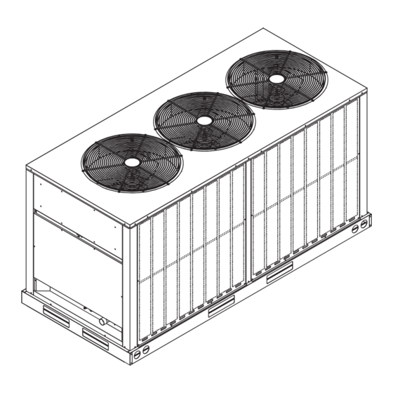
15 & 20 TON
!
Recognize this symbol as an indication of Important Safety Information!
DO NOT DESTROY. PLEASE READ CAREFULLY AND
KEEP IN A SAFE PLACE FOR FUTURE REFERENCE.
WARNING
!
THESE INSTRUCTIONS ARE INTENDED AS AN AID TO
QUALIFIED, LICENSED SERVICE PERSONNEL FOR PROPER
INSTALLATION, ADJUSTMENT AND OPERATION OF THIS UNIT.
READ THESE INSTRUCTIONS THOROUGHLY BEFORE
ATTEMPTING INSTALLATION OR OPERATION. FAILURE TO
FOLLOW THESE INSTRUCTIONS MAY RESULT IN IMPROPER
ACCREDITED
INSTALLATION, ADJUSTMENT, SERVICE OR MAINTENANCE
POSSIBLY RESULTING IN FIRE, ELECTRICAL SHOCK,
PERSONAL INJURY OR PROPERTY DAMAGE.
10 TON
92-42665-02-0
92-42665-31-04
Advertisement
Table of Contents
Troubleshooting

Related Manuals for Ruud Achiever RACL2240CBZ


Summary of Contents for Ruud Achiever RACL2240CBZ
- Page 1 INSTALLATION INSTRUCTIONS (-)ACL HIGH EFFICIENCY R-410A COMMERCIAL CONDENSING UNITS NOMINAL SIZES 10, 12.5, 15 & 20 TONS 10 & 12.5 TON 10 TON 15 & 20 TON Recognize this symbol as an indication of Important Safety Information! DO NOT DESTROY. PLEASE READ CAREFULLY AND KEEP IN A SAFE PLACE FOR FUTURE REFERENCE.
-
Page 2: Table Of Contents
TABLE OF CONTENTS 1.0 Important Safety Information ........3 5.0 Refrigerant Charging and System Start-Up ....28 2.0 General Information ............4 5.1 Start-Up Overview ..............28 5.2 Preliminary Charging by Weight and Final Leak Check ..2.1 Introduction ................4 5.3 Pre-Start Check ............... -
Page 3: Important Safety Information
1.0 IMPORTANT SAFETY INFORMATION WARNINGS: CAUTIONS: • R-410A systems operate at approximately 60% • These instructions are intended as an aid to higher pressures (1.6 times) than R-22 systems. Do qualified, licensed service personnel for proper not use R-22 service equipment or components on installation, adjustment, and operation of this R-410A equipment. -
Page 4: General Information
2.0 GENERAL INFORMATION WARNING: • NFPA90A Installation of Air Conditioning and Ventilating Systems. Improper installation, or installation not made in • NFPA90B Installation of warm air heating and air accordance with these instructions, can result conditioning systems. in unsatisfactory operation and/or dangerous conditions and can cause the related warranty Install the indoor unit in such a way as to allow not to apply. -
Page 5: Importance Of Proper Indoor/Outdoor Match-Ups
2.0 GENERAL INFORMATION 2.4 Importance of 2.6 Efficiency Testing Proper Indoor/Outdoor Notice Match-Ups For purposes of verifying or testing efficiency ratings, the test procedure in Title 10, Chapter II, Subchapter To assure many years of reliable operation and D, Part 431, Subpart F, Section 96 and the clarifying optimum customer comfort and to assure the provisions provided in the AHRI Operations outdoor unit warranty remains valid, an air-... -
Page 6: Unit Specifications
3.0 UNIT SPECIFICATIONS 3.1 Model Number Nomenclature COMPRESSOR TYPE Z = SCROLL DESIGN SERIES A = STANDARD MODEL B = DOE 2023 COMPLIANT ELECTRICAL DESIGNATION C = 208-230V, 3PH, 60HZ D = 460V, 3PH, 60HZ NOMINAL COOLING CAPACITY 120 = 120,000 BTU/HR (TWO-STAGE COMPRESSOR) 150 = 150,000 BTU/HR (TANDEM COMPRESSOR) 180 = 180,000 BTU/HR (TANDEM COMPRESSOR) 240 = 240,000 BTU/HR (TANDEM COMPRESSOR) -
Page 7: Physical And Electrical Data
3.0 UNIT SPECIFICATIONS 3.2 Electrical and Physical Data 3.2 PHYSICAL DATA AND ELECTRICAL DATA Electrical Physical Fuse or HVAC Compressor Outdoor Coil Weight Model Phase Fan Motor Minimum Circuit Breaker Refrigerant Number Frequency Number of Number Full Load Circuit Locked Rotor Rated Load Charge Face Area... - Page 8 3.0 UNIT SPECIFICATIONS 3.2 Electrical and Physical Data (cont.) UNIT DIMENSIONS — (-)ACL2120 & (-)ACL2150 (10 & 12.5 TON) CONTROL BOX END 38.375 CONTROL BOX END 72.375 72.375 HIGH VOLTAGE 1-3/4” DIA. HOLE LOW VOLTAGE 44.750 7/8” DIA. HOLE LIQUID LINE 5/8”...
- Page 9 3.0 UNIT SPECIFICATIONS 3.2 Electrical and Physical Data (cont.) ST-A0890-12 UNITS DIMENSIONS — (-)ACL2180 & (-)ACL2240 (15 & 20 TON) CONTROL BOX END 38.375 87.375 44.750 ST-A0890-13 ST-A0890-13 BASE RAILS BOTTOM...
-
Page 10: Unit Features
3.0 UNIT SPECIFICATIONS 3.3 Unit Features CABINET — Galvanized steel with a durable painted the unit. Condenser fan motors are accessible by finish. Stamped louvered panels offer 100% protection removing wire grilles. for the condenser coil. FILTER DRIER — Standard (uninstalled) on all models. COMPRESSOR —... - Page 11 3.0 UNIT SPECIFICATIONS 3.3 Unit Features (Cont.) CONTROL BOX CONFIGURATION (10-TON) (-)ACL2120 TERMINAL TERMINAL GROUND LUG TRANSFORMER STRIP BLOCKS CONTACTOR FAN MOTOR GROUNDS A0890-14 CONTROL BOX CONFIGURATION (12.5-, 15-, AND 20-TON) (-)ACL2150 (-)ACL2180 (-)ACL2240 TIME DELAY TERMINAL CONTROL GROUND LUG TRANSFORMER BLOCK FAN MOTOR...
-
Page 12: Installation
4.0 INSTALLATION 4.1 Tools and Refrigerant 4.1.1 Tools Required for Pressure: The pressure of R-410A is approximately 60% (1.6 times) greater than Installing and Servicing R-22. Recovery and recycle equipment, pumps, R-410A Models hoses, and the like must have design pressure ratings appropriate for R-410A. -
Page 13: Choosing A Location
4.0 INSTALLATION 4.2 Choosing a Location 4.2.1 Allowable Clearances 4.2.2 Operational Issues Related to Unit Location 24" [61.0 cm] to side intake louvers 24" [61.0 cm] between multiple units IMPORTANT: 36" [91.4 cm] to service access panels Locate the unit 60"... -
Page 14: Corrosive Environments
4.0 INSTALLATION 4.2 Choosing a Location (cont.) 4.2.3 Corrosive Environment WARNING: Disconnect all power to The metal parts of this unit may be subject to rust or unit before starting maintenance. Failure to do so can deterioration if exposed to a corrosive environment. cause electrical shock resulting in severe personal This oxidation could shorten the equipment’s useful injury or death. -
Page 15: Unit-Mounting Methods
4.0 INSTALLATION ROOFTOP INSTALLATION – RIGGING LIFTING BEAM SPREADER BAR CABLE, CHAIN OR WEBBING CORNER WEIGHTS – POUNDS Corner Weights LBS[kg} Total Weight Model Lbs[kg] (-)ACL2120 (-)ACL2120 565[256] 97[44] 181[82] 215[98] 73[33] (-)ACL2150 (10 &12.5 TON) (-)ACL2150 647[293] 189[86] 157[71] 161[73] 139[63] (-)ACL2180... -
Page 16: Refrigerant Line Set Selection
4.0 INSTALLATION 4.4 Refrigerant Line Set Selection 4.4.1 Replacing Existing Systems IMPORTANT: To prevent failure of a new unit, the existing line set When replacing an must be correctly sized for the new unit and must R-22 unit with an R-410A unit, either replace be cleaned or replaced. - Page 17 4.0 INSTALLATION 4.4 Refrigerant Line Set Selection (cont.) TABLE 2 Example: A 10 ton condensing unit is installed 50' This application is acceptable because the 50' below the indoor unit, requires 75' of 5/8" diameter vertical rise is less than the maximum rise of 100' liquid line, 1-3/8"...
-
Page 18: Suction Line Selection
4.0 INSTALLATION 4.4 Refrigerant Line Set Selection (cont.) 4.4.4 Suction Line Selection to carry the oil along with the refrigerant and will cause the oil to accumulate in the low spots in the Purpose of the vapor line is to return superheated vapor line instead of being returned to the com- vapor to the condensing unit from the evaporator. -
Page 19: Compressor Oil Level Adjustment
4.0 INSTALLATION 4.4 Refrigerant Line Set Selection (cont.) 4.4.5.5 Compressor Oil Level 4.4.5.6 Capacity Losses Adjustment Long line lengths can result in a reduction in capacity due to suction line pressure drop and heat gain. Refer Additional oil will need to be added for long line set ap- to Table 2 for capacity loss multipliers for various vapor plications. -
Page 20: Line Set Installation
4.0 INSTALLATION 4.5 Line Set Installation • If tubing is to be run underground, it must be run in supported. a sealed watertight chase. • Isolate the vapor line from the building structure. If • Use care in routing tubing and do not kink or twist. the vapor line comes in contact with inside walls, Use a good quality tubing bender on the vapor line ceiling, or flooring, the vibration of the vapor line... -
Page 21: Relative Location Of Indoor And Outdoor Units
4.0 INSTALLATION 4.5 Line Set Installation (cont.) 4.5.2 Relative Location of Indoor and Outdoor Units 4.5.2.1 Indoor and Outdoor Unit Near Same Level OUTDOOR UNIT LEVEL OR NEAR LEVEL TO INDOOR SECTION LINE SET REFERENCE TABLE 2 FOR MAXIMUM LENGTH LIMITATION IDEALLY, LINE SET SLOPES AWAY FROM OUTDOOR. -
Page 22: Outdoor Unit Below Indoor Unit
4.0 INSTALLATION 4.5 Line Set Installation (cont.) 4.5.2.2 Outdoor Unit Below Indoor Unit OUTDOOR UNIT BELOW INDOOR SECTION LINE SET ROUTE REFRIGERANT LINES EVEN WITH TOP OF COIL OR INSTALL INVERTED TRAP. INSULATE LIQUID LINE IN UNCONDITIONED INSULATE SUCTION SPACE FOR LONG LINE FULL LENGTH FOR ALL APPLICATIONS LINE APPLICATIONS... -
Page 23: Outdoor Unit Above Indoor Unit
4.0 INSTALLATION 4.5 Line Set Installation (cont.) 4.5.2.3 Outdoor Unit Above Indoor Unit OUTDOOR UNIT ABOVE INDOOR SECTION LINE SET INSULATE SUCTION LINE FULL LENGTH FOR ALL APPLICATIONS INSULATE LIQUID LINE IN UNCONDITIONED SPACE FOR LONG LINE APPLICATIONS REFERENCE TABLE 2 FOR MAXIMUM LENGTH AND VERTICAL SEPARATION LIMITATIONS... -
Page 24: Tubing Connections
4.0 INSTALLATION 4.5 Line Set Installation (cont.) 4.5.3 Tubing Connections Indoor coils have only a holding charge of dry nitrogen. Keep all tube ends sealed until connections are to be made. • Use type “L” copper refrigeration tubing. Braze the connections with the following alloys: –... -
Page 25: Initial Leak Testing
4.0 INSTALLATION 4.6 Initial Leak Testing 4.7 Evacuation Indoor coils have only a holding charge of dry Evacuation is one of the most important parts of the nitrogen. Keep all tube ends sealed until connections entire installation and service procedure. The life and are to be made. -
Page 26: Control Wiring
4.0 INSTALLATION 4.8 Control Wiring WARNING: below to size the 24-volt control wiring. Turn off electric power Do not use phone cord to connect indoor and at the fuse box or service panel before making outdoor units and thermostat. This could damage any electrical connections. -
Page 27: Configuring Control Transformer For 208V Applications
4.0 INSTALLATION 4.10 Configuring Control Transformer for 208V Applications The control transformer supplied with 208/230V in the unit electrical box. (See illustration on models is factory wired for 230V applications page 11 of this manual. The lugs will be on the and must be reconfigured for 208V applications compressor contactor for the 10 Ton model and on upon installation by disconnecting the Orange... -
Page 28: Refrigerant Charging And System Start-Up
5.0 SYSTEM START-UP & REFRIGERANT CHARGING 5.1 Start-Up Overview 5.2 Preliminary Charging by Weight and Once the system hardware and wiring have been properly installed and the system has been Final Leak Check properly evacuated, the next step is to weigh in the preliminary refrigerant charge and conduct a After the system has been properly evacuated, final leak check before applying electrical power... -
Page 29: Pre-Start Check
5.0 SYSTEM START-UP & REFRIGERANT CHARGING Charge Adjustment = Total Linear Line Length x (oz/ft or g/m for liquid line + oz/ft or g/m for suction line) Preliminary Refrigerant Charge = Basic System Charge + Charge Adjustment Example: A 10 ton system requires 75 ft. of line set with a 5/8” liquid line and 1-3/8” suction line. Charge Adjustment = 75 ft. -
Page 30: Motor And Compressor Rotation
5.0 SYSTEM START-UP & REFRIGERANT CHARGING 5.4 Initial System Directory, manufacturer’s specifications, or engineer’s specification for the matched system. Start-Up: Verifying If this information is not available, 350 - 400 CFM per ton is a good rule of thumb. Refer to the air- Correct Indoor Blower handler or gas furnace installation and operation Motor and Compressor... - Page 31 5.0 SYSTEM START-UP & REFRIGERANT CHARGING NOTICE: system. Allow the system to stabilize for 5 If the indoor temperature is above minutes before rechecking the pressures against or below the recommended range, run the the chart. system to bring the temperature down or run the electric heat/furnace to bring the temperature 6) Repeat steps 4 and 5 as required.
-
Page 32: Charging Charts
5.0 SYSTEM START-UP & REFRIGERANT CHARGING 5.7 CHARGING CHARTS Split System Air Conditioner 10 Tons System Charge Chart - Refrigerant 410A Basic System Charge With 0 Feet Of Tubing = 422 oz. Add Additional Amount As Shown In Table Below Cooling Instructions Caution: Return Air Temperature Must Be Between 70°... - Page 33 5.0 SYSTEM START-UP & REFRIGERANT CHARGING 5.7 CHARGING CHARTS Split System Air Conditioner 12.5 Tons System Charge Chart - Refrigerant 410A Basic System Charge With 0 Feet Of Tubing = 414 oz. Add Additional Amount As Shown In Table Below Cooling Instructions Caution: Return Air Temperature Must Be Between 70°...
- Page 34 5.0 SYSTEM START-UP & REFRIGERANT CHARGING 5.7 CHARGING CHARTS Split System Air Conditioner 15 Tons System Charge Chart - Refrigerant 410A Basic System Charge With 0 Feet Of Tubing = 582 oz. Add Additional Amount As Shown In Table Below Cooling Instructions Caution: Return Air Temperature Must Be Between 70°...
- Page 35 5.0 SYSTEM START-UP & REFRIGERANT CHARGING 5.7 CHARGING CHARTS Split System Air Conditioner 20 Tons System Charge Chart - Refrigerant 410A Basic System Charge With 0 Feet Of Tubing =650 oz Add Additional Amount As Shown In Table Below Cooling Instructions COOLING Caution: Return Air Temperature Must Be Between 70°...
-
Page 36: Completing Installation
5.0 SYSTEM START-UP & REFRIGERANT CHARGING 5.8 Completing Installation • Disconnect the hoses from the pressure ports. Replace the pressure port caps and tighten adequately to seal caps. Do not overtighten. • Replace the service valve top caps finger-tight and then tighten with a wrench to adequately seal caps. Do not overtighten. -
Page 37: Components & Controls
6.0 SEQUENCE OF OPERATION stopping compressor operation and closing the and closing the auxiliary contacts (AUX1), which auxiliary contacts (AUX2), which energizes the energizes the crankcase heater (CCH1). crankcase heater (CCH2). 8. The thermostat “G” circuit will stop blower 7. When continued cooling satisfies the “Y1” circuit, operation. -
Page 38: Transformer
7.0 COMPONENTS & CONTROLS 7.8 Line Voltage Termi- 7.9 Transformer nal Block for Field Con- A 75VA (10-12.5 ton) or 100VA (15-20 ton) nections transformer is provided inside the unit control box for supplying 24V AC for both the outdoor and 12.5 –... -
Page 39: Diagnostics And Troubleshooting
9.0 DIAGNOSTICS & TROUBLESHOOTING 9.1 Cooling Mechanical Checks Flowchart... -
Page 40: General Troubleshooting Guide
9.0 DIAGNOSTICS & TROUBLESHOOTING 9.2 General Troubleshooting Guide WARNING: Disconnect all power to unit before servicing. Contactor may break only one side. Failure to shut off power can cause electrical shock resulting in personal injury or death. SYMPTOM POSSIBLE CAUSE REMEDY Unit will not run •... -
Page 41: Service Analyzer Charts
9.0 DIAGNOSTICS & TROUBLESHOOTING 9.3 Service Analyzer Charts COMPRESSOR OVERHEATING SYMPTOM POSSIBLE CAUSE CHECK/REMEDY High superheat Low charge Check system charge. (greater than 15°F Faulty metering device Restricted cap tube, TXV [8.3°C] at coil) Power element superheat out of adjustment internally Foreign matter stopping flow High internal load Hot air (attic) entering return... - Page 42 9.0 DIAGNOSTICS & TROUBLESHOOTING 9.3 Service Analyzer Charts (cont.) COMPRESSOR OVERHEATING (cont.) SYMPTOM POSSIBLE CAUSE CHECK OR REMEDIES Short cycling of Low charge Check system charge. compressor (cont.) Low evaporator airflow Dirty coil Dirty filter Duct too small or restricted Faulty run capacitor Replace.
- Page 43 9.0 DIAGNOSTICS & TROUBLESHOOTING 9.3 Service Analyzer Charts (cont.) CONTAMINATION SYMPTOM POSSIBLE CAUSE REMEDY Moisture Poor evacuation on installation or during service High head pressure Noncondensibles air Unusual head and Wrong refrigerant or mixed refrigerants suction readings Foreign matter – Copper tubing cuttings In each case, the cure is the same.
- Page 44 9.0 DIAGNOSTICS & TROUBLESHOOTING 9.3 Service Analyzer Charts (cont.) FLOODING SYMPTOM POSSIBLE CAUSE REMEDY Loose sensing bulb Secure the bulb and insulate. Bulb in wrong location Relocate bulb. Poor system control using a TXV Wrong size TXV Use correct replacement. Improper superheat setting (less than 5°F [2.8°C]) Replace TXV.
- Page 45 9.0 DIAGNOSTICS & TROUBLESHOOTING 9.3 Service Analyzer Charts (cont.) THERMOSTATIC EXPANSION VALVES (cont.) SYMPTOM POSSIBLE CAUSE REMEDY Refrigerant drainage from flooded evaporator Install trap riser to the top of the evaporator coil. Compressor flood Inoperable crankcase heater or crankcase heater Replace or add crankcase heater.
-
Page 46: Troubleshooting Tips
9.0 DIAGNOSTICS & TROUBLESHOOTING 9.4 Troubleshooting Tips COOLING MODE TROUBLESHOOTING TIPS INDICATORS SYSTEM DISCHARGE SUCTION SUPERHEAT SUBCOOLING COMPRESSOR PROBLEM PRESSURE PRESSURE Normal: 5°–15°F Normal: See AMPS [2.8° – 8.3°C] Charging Chart Overcharge High High High High Undercharge High Liquid Restriction High High (Filter Drier) -
Page 47: Outdoor Unit Maintenance
10.0 OUTDOOR UNIT MAINTENANCE 10.1 Outdoor Coil Cleaning The outdoor fan draws air across the coil during an angle. Washing from the top of the coil down operation which results in contaminants collecting from the inside out is the most effective method on and between the aluminum fins. -
Page 48: Wiring Diagrams
11.0 WIRING DIAGRAMS 11.1 (-)ACL2120 WIRING DIAGRAM/SCHEMATIC (10 TON) - Page 49 11.0 WIRING DIAGRAMS 11.2 (-)ACL2150, (-)ACL2180, (-)ACL2240 WIRING DIAGRAM (12.5, 15 & 20 TON)
- Page 50 11.0 WIRING DIAGRAMS 11.3 (-)ACL2150, (-)ACL2180, (-)ACL2240 WIRING SCHEMATIC (12.5, 15 & 20 TON)
Need help?
Do you have a question about the Achiever RACL2240CBZ and is the answer not in the manual?
Questions and answers