
Related Manuals for Ruud RHPBZR Series


Summary of Contents for Ruud RHPBZR Series
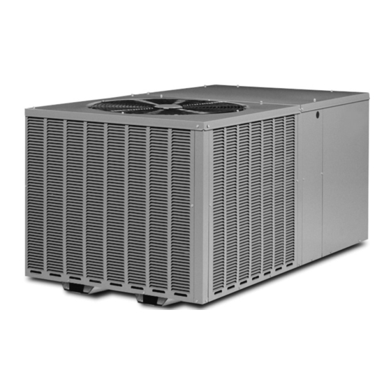
- Page 1 INSTALLATION INSTRUCTIONS PACKAGED HEAT PUMPS FEATURING EARTH-FRIENDLY R-410A REFRIGERANT RHPBZR (2-5 TONS) 13.4 SEER2 92-108851-01-00...
-
Page 2: Table Of Contents
WARNING THESE INSTRUCTIONS ARE INTENDED AS AN AID TO QUALIFIED, LICENSED SERVICE PERSONNEL FOR PROPER INSTALLATION, ADJUSTMENT AND OPERATION OF THIS UNIT. READ THESE INSTRUCTIONS THOROUGHLY BEFORE ATTEMPTING INSTALLATION OR OPERATION. FAILURE TO FOLLOW THESE INSTRUCTIONS MAY RESULT IN IMPROPER INSTALLATION, ADJUSTMENT, SERVICE OR MAINTENANCE POSSIBLY RESULTING IN FIRE, ELECTRICAL SHOCK, PROPERTY DAMAGE, PERSONAL INJURY OR DEATH. -
Page 3: Safety Information
I. SAFETY INFORMATION WARNING WARNING PROPOSITION 65: THIS APPLIANCE CONTAINS FIBER- TURN OFF ELECTRIC POWER AT THE FUSE BOX OR GLASS INSULATION. RESPIRABLE PARTICLES OF SERVICE PANEL BEFORE MAKING ANY ELECTRICAL FIBERGLASS ARE KNOWN TO THE STATE OF CALI- CONNECTIONS. FORNIA TO CAUSE CANCER. -
Page 4: Breakdown Page
II. BREAKDOWN PAGE R HP B ZR 036 A J T 10 1 N A X X X Factory Installed Options (See Spec Sheet) Minor Series A = 1st Variation Control N = Non Communicating Heat Configuration 1 = Single Stage Heating Capacity 00 = No Heat 05 = 05 kW... -
Page 5: Introduction
III. INTRODUCTION V. IMPORTANCE OF A QUALITY This booklet contains the installation and operating instructions for INSTALLATION your packaged heat pump unit. There are some precautions that should be taken to ensure proper operation. Improper installation Optimal system performance and longevity depend upon a can result in unsatisfactory operation or dangerous conditions. - Page 6 FRONT VIEW FIGURE 1 UNIT DIMENSIONS AND ACCESS LOCATIONS [1498.6 mm] Model RHPBZR Height “A” CONDENSATE DRAIN 024, 030 29 1/8” ACCESS 036, 042, 048, 060 37 1/8” CONTROL BOX ACCESS [77.7 mm] [1358.9 mm] [266.7 mm] [266.7 mm] BOTTOM VIEW ELECTRICAL CONNECTIONS RECOMMENDED UNIT DISCONNECT LOCATION...
- Page 7 FIGURE 1 (Continued) DUCT CONNECTIONS ROUND DUCT CONNECTIONS [355.6 mm] [355.6 mm] SQUARE DUCT CONNECTIONS " 14.00" 14.00" " [19.05 mm] [355.6 mm] [19.05 mm] [355.6 mm] 14.00" 14.00" [355.6 mm] [355.6 mm] IMPORTANT: DO NOT SCREW OR DRILL OUTSIDE THE DESIGNATED AREAS. IMPORTANT: This product is designed to be operated with 14( round supply and re- turn air ducts.
-
Page 8: Installation
VIII. INSTALLATION B. OUTSIDE SLAB INSTALLATION (Typical outdoor slab installations are shown in Figure 2.) A. GENERAL 1. PRE-INSTALLATION CHECK-POINTS 1. Select a location where external water drainage cannot col- Before attempting any installation, the following points lect around the unit. should be carefully considered: 2. - Page 9 FIGURE 2 PACKAGED HEAT PUMP OUTSIDE SLAB INSTALLATION, BASEMENT OR CRAWL SPACE DISTRIBUTION SYSTEM FIGURE 3 PACKAGED HEAT PUMP PITCHED ROOFTOP INSTALLATION, ATTIC OR DROP CEILING DISTRIBUTING SYSTEM. MUST BE MOUNTED LEVEL.
-
Page 10: Ductwork
IX. DUCTWORK XI. CONDENSATE DRAIN Ductwork should be fabricated by the installing contractor in ac- The indoor coil condensate drain ends with a PVC stub. A trap is cordance with local codes and NFPA90A. Industry manuals may provided for proper condensate drainage and to prevent debris be used as a guide when sizing and designing the duct system from being drawn into the unit. -
Page 11: Power Wiring And Electric Heater Kit Instructions
high voltage field power circuit leads to the heater kit B. POWER WIRING AND ELECTRIC HEATER KIT fuse block and connect ground lead to ground lug on INSTRUCTIONS heater kit fuse block. Connect the second set of high voltage field power WARNING leads to L1 and L3 on the unit contactor. -
Page 12: Thermostat
k. Model Number ________________________________ F. THERMOSTAT l. Serial Number __________________________________ Mount the thermostat on an inside wall about five feet above m. Location _____________________________________ the floor in a location where it will not be affected by uncon- n. Owner _______________________________________ ditioned air, sun, or drafts from open doors or other sources. -
Page 13: Demand Defrost Control And High/Low Pressure Controls
XIX. DEMAND DEFROST CONTROL 4. Release test pins once control exits noise abatement delay. AND HIGH/LOW PRESSURE 5. Monitor coil temperature when control exits defrost. CONTROLS 6. Unit should return to heating mode. The demand defrost control monitors the outdoor ambient temperature, outdoor coil temperature and the compressor run TROUBLESHOOTING DEMAND DEFROST time to determine when a defrost cycle is required. - Page 14 E N H A N C E D F E AT U R E D E F R O S T C O N T R O L DIAGNOSTIC CODES SENSOR TEMPERATURE VS. RESISTANCE TABLE LED 1 LED 2 Control Board Status No Power Coil Sensor Failure Ambient Sensor Failure...
-
Page 15: General Data - Rhpb
XX. GENERAL DATA - RHPB NOMINAL SIZES 2-5 TONS [7-17.6 kW] Model RHPBZR Series 024AJT 030AJT 036AJT 042AJT Cooling Performance Continued -> Gross Cooling Capacity Btu [kW] 24,000 [7.03] 29,000 [8.5] 36,200 [10.61] 41,000 [12.01] EER2/SEER2 10.6/13.4 10.6/13.4 10.6/13.4 10.6/13.4... - Page 16 GENERAL DATA - RHPB NOMINAL SIZES 2-5 TONS [7-17.6 kW] Model RHPBZR Series 048AJT 060AJT Cooling Performance Gross Cooling Capacity Btu [kW] 48,000 [14.06] 58,500 [17.14] EER2/SEER2 10.6/13.4 10.6/13.4 Nominal CFM/AHRI Rated CFM [L/s] 1600/1600 [755/755] 2000/1900 [944/897] AHRI Net Cooling Capacity Btu [kW] 46,500 [13.62]...
-
Page 17: Electrical Data
XXI. ELECTRICAL DATA ELECTRICAL DATA – RQPM- SERIES 024AJT 030AJT 036AJT 042AJT 048AJT 060AJT Unit Operating Voltage Range 187-253 187-253 187-253 187-253 187-253 187-253 Volts 208/230 208/230 208/230 208/230 208/230 208/230 Phase Minimum Circuit Ampacity Minimum Overcurrent Protection Device Size Maximum Overcurrent Protection Device Size Volts... -
Page 18: Airflow Performance
XXII. AIRFLOW PERFORMANCE INDOOR AIRFLOW PERFORMANCE FOR 2-5 TON PACKAGED HEAT PUMPS – 230V RHPB SERIES... -
Page 19: Heater Kit Characterstics
XXIII. HEATER KIT CHARACTERSTICS ELECTRIC HEATER KIT – 1 PHASE RHPB 208/240 VOLT, SINGLE PHASE, 60 Hz, AUXILIARY ELECTRIC HEATER KITS CHARACTERISTICS AND APPLICATION Single Power Supply for Both Unit and Heater Kit Separate Power Supply for Both Unit and Heater Kit Heater Kit Heat Pump Heater Kit... -
Page 20: Wiring Diagrams
XXIV. WIRING DIAGRAMS FIGURE 7 WIRING DIAGRAM... - Page 21 FIGURE 8 WIRING DIAGRAM...
Need help?
Do you have a question about the RHPBZR Series and is the answer not in the manual?
Questions and answers