Table of Contents
Advertisement
INST LL TION INSTRUCTIONS
FOR P CK GE HE T PUMPS FE TURING
E RTH-FRIENDLY R410 REFRIGER NT
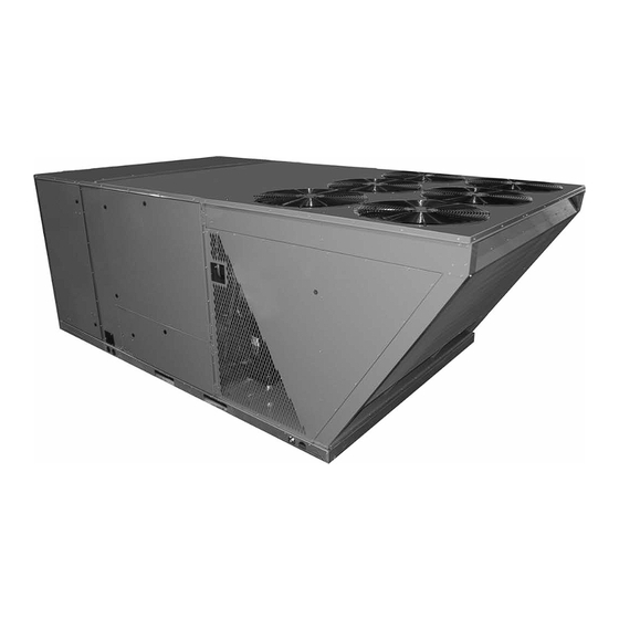
RJNL-B SERIES 15 TON [52.8 kW]
60 HZ MODELS (COMPLIES WITH ASHRAE 90.1-2007)
!
RECOGNIZE THIS SYMBOL AS AN INDICATION OF IMPORTANT SAFETY INFORMATION!
WARNING
!
THESE INSTRUCTIONS ARE INTENDED AS AN AID TO
QUALIFIED, LICENSED SERVICE PERSONNEL FOR
PROPER INSTALLATION, ADJUSTMENT AND
OPERATION OF THIS UNIT. READ THESE INSTRUCTIONS
THOROUGHLY BEFORE ATTEMPTING INSTALLATION
OR OPERATION. FAILURE TO FOLLOW THESE
INSTRUCTIONS MAY RESULT IN IMPROPER
INSTALLATION, ADJUSTMENT, SERVICE OR
MAINTENANCE POSSIBLY RESULTING IN FIRE,
PLEASE READ CAREFULLY AND KEEP IN A SAFE PLACE FOR FUTURE REFERENCE BY A SERVICEMAN
DO NOT DESTROY THIS MANUAL
[ ] INDICATES METRIC CONVERSIONS
t
i
n
d
y r e f r i g e r a n t
e
e a r
e a r t h f r i e n d l y r e f r i g e r a n t
r
t h
h f r
h
r i e
i
e n
d l
d l y
y r
92-23577-112-02
SUPERSEDES 92-23577-112-01
Advertisement
Table of Contents

Subscribe to Our Youtube Channel
Related Manuals for Ruud RJNL-B SERIES


Summary of Contents for Ruud RJNL-B SERIES
- Page 1 RJNL-B SERIES 15 TON [52.8 kW] 60 HZ MODELS (COMPLIES WITH ASHRAE 90.1-2007) RECOGNIZE THIS SYMBOL AS AN INDICATION OF IMPORTANT SAFETY INFORMATION! WARNING THESE INSTRUCTIONS ARE INTENDED AS AN AID TO...
-
Page 2: Table Of Contents
I. T BLE OF CONTENTS Table of Contents ..........2 Introduction . -
Page 3: Introduction
II. INTRODUCTION W RNING W RNING PROPOSITION 65: THIS APPLIANCE CONTAINS FIBERGLASS INSULA- TION. RESPIRABLE PARTICLES OF THE MANUFACTURER’S WARRANTY DOES NOT COVER ANY DAMAGE OR FIBERGLASS ARE KNOWN TO THE DEFECT TO THE AIR CONDITIONER CAUSED BY THE ATTACHMENT OR USE STATE OF CALIFORNIA TO CAUSE OF ANY COMPONENTS, ACCESSORIES OR DEVICES (OTHER THAN THOSE CANCER. -
Page 4: Specifications
Several different types of protective coatings are offered in some areas. These coat- ings may provide some benefit, but the effectiveness of such coating materials cannot be verified by the equipment manufacturer. The best protection is frequent cleaning, maintenance and minimal exposure to contaminants. - Page 5 3. Evaporator Coil / TXV The biflow thermostatic expansion valve is specifically designed to operate with R- 410A. DO NOT use an R-22 TXV. The existing evaporator must be replaced with the factory specified TXV evaporator specifically designed for R-410A. 4.
-
Page 6: Unit Dimensions
FIGURE 1 UNIT DIMENSIONS (BOTTOM VIEW) CONDENSER COIL (RIGHT SIDE) BLOWER ACCESS CONTROL ACCESS SUPPLY RETURN Typical Dimensions Shown in Inches (± .125) ST-A1125-02B FIGURE 2 UNIT DIMENSIONS (BOTTOM VIEW) (FRONT SIDE) ALTERNATE ELECTRICAL ENTRY ELECTRICAL ENTRY (POWER) (LOW VOLTAGE) (RIGHT SIDE) RETURN... - Page 7 FIGURE 3 UNIT DIMENSIONS COMPRESSOR ACCESS SUPPLY COVER NOTE: 15 TON UNIT DOES NOT HAVE FANS #2 & #5. ST-A1125-03 RETURN COVER FIGURE 4 UNIT DIMENSIONS RETURN REAR VIEW CONDENSER COIL (RIGHT SIDE) SUPPLY AIR ST-A1125-08B FIGURE 5 OUTDOOR FAN #4 COMPONENT LOCATION OUTDOOR FAN #5 OUTDOOR FAN #1...
-
Page 8: Unit Dimensions
FIGURE 6 Condenser Fan UNIT DIMENSIONS & COMPONENT ACCESS (FRONT SIDE) Discharge Air Compressor Access (Both Sides) Control Box Blower Access Condenser & Coil Filter Access (Right Side) Electric Heat Access Condensate Drain 1” FNPT ST-A1125-06B FIGURE 7 UNIT DIMENSIONS & COMPONENT ACCESS OUTDOOR FANS COMPRESSOR ACCESS... -
Page 9: General Data
GENERAL DATA - RJNL Model RJNL- Series B180CL B180CM B180DL B180DM Continued -> Cooling Performance Gross Cooling Capacity Btu [kW] 182,000 [53.33] 182,000 [53.33] 182,000 [53.33] 182,000 [53.33] EER/SEER 10.7/NA 10.7/NA 10.7/NA 10.7/NA Nominal CFM/AHRI Rated CFM [L/s] 6000/6025 [2831/2843] 6000/6025 [2831/2843] 6000/6025 [2831/2843] 6000/6025 [2831/2843]... -
Page 10: General Data
GENERAL DATA - RJNL Model RJNL- Series B180YL B180YM Cooling Performance Gross Cooling Capacity Btu [kW] 182,000 [53.33] 182,000 [53.33] EER/SEER 10.7/NA 10.7/NA Nominal CFM/AHRI Rated CFM [L/s] 6000/6025 [2831/2843] 6000/6025 [2831/2843] AHRI Net Cooling Capacity Btu [kW] 176,000 [51.57] 176,000 [51.57] Net Sensible Capacity Btu [kW] 133,600 [39.14]... -
Page 11: Electrical Data
ELECTRICAL DATA - RJNL ELECTRICAL DATA - RJNL SERIES B180CL B180CM B180DL B180DM B180YL B180YM Unit Operating Voltage 187-253 187-253 414-506 414-506 518-632 518-632 Range Volts 208/230 208/230 Minimum Circuit 78/78 81/81 Ampacity Minimum Overcurrent 90/90 90/90 Protection Device Size Maximum Overcurrent 100/100 100/100... -
Page 12: Installation
VI. INST LL TION . GENER L 1. PRE-INSTALLATION CHECK-POINTS Before attempting any installation, the following points should be carefully considered: a. Structural strength of supporting members. (rooftop installation) b. Clearances and provision for servicing. c. Power supply and wiring. d. -
Page 13: Clearances
C. CLE R NCES FIGURE 11 The following minimum clearances must be observed for prop- er unit performance and serviceability. 1. Provide 80" minimum clearance at the front of the unit. Provide 18" minimum clearance at all other sides of the unit. 2. -
Page 14: Ductwork
VII. DUCTWORK Ductwork should be fabricated by the installing contractor in accordance with local codes and NFPA90A. Industry manuals may be used as a guide when sizing and designing the duct sys- tem - contact Air Conditioning Contractors of America, 2800 Shirlington Road, Suite 300, Arlington, VA 22206, http:/www.acca.org. -
Page 15: Cover Panel Installation/Conversion Procedure
IX. COVER P NEL INST LL TION/ VIIICONVERSION PROCEDURE DOWNFLOW TO HORIZONTAL 1. Remove the screws and covers from the outside of the supply and return sections. Also remove and discard cover plate. See Figure 3. 2. Install the covers over the bottom supply and return openings, painted side up, inserting the leading flange under the bracket provided. -
Page 16: Electrical Wiring
XII. ELECTRIC L WIRING Field wiring must comply with the National Electrical Code* and local ordinances that may apply. *C.E.C. in Canada A. POWER WIRING 1. This unit incorporates single-point electrical connections for the unit and electric heat accessory. 2. It is important that proper electrical power is available to the unit. Voltage should not vary more than 10% from the values marked on the unit rating plate. -
Page 17: Indoor Air Flow Data
FIGURE 17 THERMOSTAT CONNECTIONS DIAGRAMS STANDARD WIRING ALTERNATE LOW VOLTAGE WIRING WITH OUTDOOR THERMOSTAT ONLY USED ONLY USED ON DUAL ON DUAL FUEL OR HEAT FUEL OR HEAT PUMP PUMP IFC BOARD LOW VOLTAGE MODELS IFC BOARD LOW VOLTAGE MODELS THERMOSTAT CONNECTIONS THERMOSTAT CONNECTIONS A1 A2... -
Page 19: Startup
5. Is unit grounded? 6. Are field supplied air filters in place and clean? 7. Do the outdoor fan and indoor blower turn freely without rubbing, and are they tight on the motor shafts? 8. Is unit elevated to allow for outdoor coil condensate drainage during heating operation and defrost? XVI. -
Page 20: Auxiliary Heat
A. Indoor blower contactor is energized through thermostat contact (G). W RNING B. Compressor contactors are energized through thermostat contacts (Y1) and (Y2). A 5 minute short cycle delay is standard on this unit. Compressor will start immediate- ONLY ELECTRIC HEATER KITS SUP- ly if test pins on the defrost board are shorted and released. - Page 21 DEFROST TERMIN TION Once a defrost is initiated, the defrost will continue until fourteen minutes has elapsed or the coil temperature has reached the selected termination temperature. The facto- ry setting is 70°F but can be changed to 50°F, 60°F, or 80°F by relocating the jumper on the control board.
- Page 22 approximately 40 psig when the low pressure control automatically resets. If the low pressure switch trips 3 times within 120 minutes of operation during a partic- ular call for heating operation, the defrost control will lock out compressor and out- door fan operation.
-
Page 23: Heater Kit Characteristics
XX. HEATER KIT CHARACTERISTICS TABLE G. AUXILIARY HEATER KITS CHARACTERISTICS AND APPLICATION (15, 20 & 25 TON MODELS) 208/240 VOLT, THREE PH SE, 60 HZ, UXILI RY ELECTRIC HE TER KITS CH R CTERISTICS ND PPLIC TION Single Power Supply for Both Unit and Heater Kit Separate Power Supply for Both Unit and Heater Kit Heater Kit ir Conditioner... -
Page 24: Troubleshooting Chart
TROUBLE SHOOTING CHART WARNING DISCONNECT ALL POWER TO UNIT BEFORE SERVICING. CONTACTOR MAY BREAK ONLY ONE SIDE. FAILURE TO SHUT OFF POWER CAN CAUSE ELECTRICAL SHOCK RESULTING IN PERSONAL INJURY OR DEATH. SYMPTOM POSSIBLE CAUSE REMEDY Unit will not run •... - Page 26 NOTE: 15 TON UNIT DOES NOT HAVE OFM 2 & 5.
-
Page 27: Charge Charts
RJNL SERIES – 15 TON 15 TON HP (R410A) SYSTEM 1 SYSTEM CHARGE CHART (COOLING) SUCTION PRESSURE - PSIG SYSTEM CHARGE CHART (HEATING) SUCTION PRESSURE - PSIG 92-102380-12-00... - Page 28 RJNL SERIES – 15 TON CM 0913...
Need help?
Do you have a question about the RJNL-B SERIES and is the answer not in the manual?
Questions and answers