
Related Manuals for Gema OptiFlex 2 W


Summary of Contents for Gema OptiFlex 2 W
- Page 1 Quick reference guide Manual coating equipment OptiFlex 2 W Translation of the original operating instructions...
- Page 2 To the best of our knowledge and belief, the information contained in this publication was correct and valid on the date of publication. Gema Switzerland GmbH makes no representations or warranties with respect to the contents or use of this publication, and reserves the right to revise this publication and make changes to its content without prior notice.
-
Page 3: Table Of Contents
V 08/15 Table of contents General safety regulations OptiFlex 2 W Technical data ....................... 11 Commissioning ...................... 14 Initial start-up ......................17 Operation ......................19 Color change ......................25 Cleaning and maintenance ................... 29 Fault remedying ....................33 Spare parts list ...................... 35 OptiStar CG13 Fault remedying .................... -
Page 5: General Safety Regulations
General safety regulations This chapter sets out the fundamental safety regulations that must be followed by the user and third parties using OptiFlex 2 W manual coating equipment. These safety regulations must be read and understood in full before the OptiFlex 2 W is put into operation. - Page 6 V 08/15 The OptiFlex 2 W manual coating equipment is state of the art equipment that conforms to the recognized technical safety regulations and is designed for normal powder coating applications. Any other use is considered non-compliant. The manufacturer shall not be liable for damage resulting from such use;...
- Page 7 The use of other parts can lead to risk of injury. Only original Gema spare parts should be used! Repairs must only be carried out by specialists or by authorized Gema service centers. Unauthorized conversions and modifications can lead to injuries and damage to the equipment, and the Gema Switzerland GmbH guarantee would no longer be valid.
- Page 8 Smoking and igniting fire are forbidden in the entire vicinity of the system! No work that could potentially produce sparks is allowed! Fire and smoke prohibition 6 • OptiFlex 2 W...
- Page 9 (e.g. leather soles). The operating personnel should hold the gun with bare hands. If gloves are worn, these must also conduct electricity. These general safety regulations must be read and understood in all cases prior to start-up! • 7 OptiFlex 2 W...
-
Page 11: Optiflex 2 W
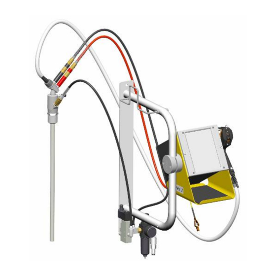
NOTE: For further information, see the corresponding operating manual, which can be found on the accompanying CD. Structure OptiFlex 2 W manual coating equipment - Structure 1 OptiStar CG13 Gun control unit 10 Filter unit OptiSelect GM03 manual powder 11 Gun holder... - Page 12 OptiFlow injector Wall bracket with gun/hose holder filter unit Suction tube PowerClean module** Pneumatic hoses for conveying air (red), supplementary air (black), fluidizing air (black) and rinsing air (black) Operating manual Short instructions 10 • OptiFlex 2 W...
-
Page 13: Technical Data
Technical data OptiFlex 2 W Connectable guns OptiFlex 2 W connectable OptiSelect GM03 WARNING: The OptiFlex 2 W manual coating equipment can only be used with the specified gun types! Electrical data OptiFlex 2 W Nominal input voltage 100-240 VAC Frequency... - Page 14 V 08/15 Pneumatic data OptiFlex 2 W Max. input pressure 10 bar Min. input pressure 6 bar Input pressure (Dynamic based on pressure 5.5 bar / 80 psi regulator setting) Max. water vapor content of the compressed 1,3 g/m³ Max. oil vapor content of the compressed air 0,1 mg/m³...
- Page 15 The total air consumption for the device is determined for each device type based on the 3 configured air values (without AirMover air value for OptiFlex F). These values apply for an internal control pressure of 5.5 bar! • 13 OptiFlex 2 W...
-
Page 16: Commissioning
V 08/15 Commissioning Connection instructions The OptiFlex 2 W manual coating equipment must be connected in accordance with the setup and connection instructions (Please also review the operating instructions for the OptiStar CG13 manual gun control unit). Maintenance unit 6 - 10 bar... - Page 17 2.4 PowerClean Conveying air connection Supplementary air connection Electrode rinsing air connection Fluidizing air connection Grounding connection Pin assignment Power IN connection Neutral conductor (power supply) Phase (100-240 VAC) Output vibrator or stirrer Grounding PE • 15 OptiFlex 2 W...
-
Page 19: Initial Start-Up
The remainder of the start-up procedure for the OptiSelect GM03 manual powder gun is explicitly described in the operating instructions for the OptiStar CG13 manual powder gun control unit (chapter "Initial start-up" and "Daily start-up")! • 17 OptiFlex 2 W... - Page 20 (For more on this, please also see the operating instructions for the OptiStar CG13 manual gun control unit)! NOTE: The manual gun control unit always starts up to the last configured settings. 18 • OptiFlex 2 W...
-
Page 21: Operation
► The manual equipment may only be operated in conjunction with a sufficiently powerful suction unit (such as Gema Classic Open booth). 1. Turn on the gun control unit with the ON key The displays illuminate and the control unit is ready for operation 2. - Page 22 Description Presetting Powder output Total air 0 Nm³/h High voltage 0 kV 0 µA Spray current 0,1 Nm³/h Electrode rinsing air Fluidizing air 0.1 Nm³/h (for OptiFlex-B and S) 8. Setting the total air volume 20 • OptiFlex 2 W...
- Page 23 ► If values are entered that the equipment cannot implement, then the operator is informed of this by a blinking in the relevant display and a temporary error message! 10. Setting the electrode rinsing air a) Press the key The second display level will be shown • 21 OptiFlex 2 W...
- Page 24 In moist or tropical environments, any moisture is driven from the injector, powder hose and powder gun. NOTE: The injector must be detached prior to rinsing procedure! a) Detach the injector 22 • OptiFlex 2 W...
- Page 25 Manual equipment with optional PowerClean module (system parameter P01=1) The rinsing mode can only be activated from standby mode (main menu display, no powder conveying). 1. Press the key for 3 seconds WARNING: The rinsing procedure is started directly. • 23 OptiFlex 2 W...
- Page 26 The rinsing mode is exited if the automatic rinsing sequence has finished. 3. STOP = After completion of the PowerClean procedure, the controller switches back to coating mode. 24 • OptiFlex 2 W...
-
Page 27: Color Change
All powder particles of the former color must be removed during this process! The following describes an 'extreme' color change (light to dark). Press these two keys at the same time for 3 seconds • 25 OptiFlex 2 W... - Page 28 17. Clean suction intake pipe 18. Empty remaining powder into a container 19. Vacuum up container and in particular the bottom 20. Clean container with a cloth 21. Reconstruct the powder container 22. Fill with new powder 26 • OptiFlex 2 W...
- Page 29 The adjustments for high voltage, powder output, electrode rinsing air and fluidizing remain stored! If in disuse for several days 1. Separate from power mains 2. Clean the coating equipment (see the corresponding operating manual) 3. Turn off the compressed air main supply • 27 OptiFlex 2 W...
-
Page 31: Cleaning And Maintenance
Cleaning and maintenance NOTE: Regular and conscientious maintenance increases the service life of the OptiFlex 2 W manual coating equipment and provides for a longer continuous coating quality! The parts, which are to be replaced during maintenance work, are available as spare parts. These parts will be found in the... - Page 32 Daily: 1. Blow off the outside of the gun and wipe, clean etc. Weekly: 2. Remove the powder hose from the connection 3. Remove the spray nozzle from the gun and clean it 30 • OptiFlex 2 W...
- Page 33 6. Blow through the gun with compressed air again 7. Clean the powder hose 8. Reassemble the gun and connect it NOTE: Please also review the user manual for the OptiSelect GM03 manual powder gun! • 31 OptiFlex 2 W...
-
Page 35: Fault Remedying
Gun not connected Connect the gun dark, although the gun is triggered Gun plug, gun cable or Contact local Gema gun cable connection representative defective Remote control on Contact local Gema powder gun defective representative • 33 OptiFlex 2 W... - Page 36 Fluidizing air is set too Set the fluidizing air low on the control unit correctly Throttle motor defective Contact local Gema representative No electrode rinsing air Rinsing air throttle motor Contact local Gema defective representative 34 • OptiFlex 2 W...
-
Page 37: Spare Parts List
Ø 8/6 mm, 8 mm outside diameter (o/d) / 6 mm inside diameter (i/d) WARNING! Only original Gema spare parts should be used, because the explosion protection will also be preserved that way. The use of spare parts from other manufacturers will invalidate the Gema guarantee conditions! •... - Page 38 V 08/15 OptiFlex 2 W manual coating equipment – Spare Parts CG13 gun control unit – complete (see corresponding operating manual) 1009 971 GM03 manual powder gun – complete (see corresponding user manual) 1008 070 IG06 injector – complete (see corresponding user manual)
- Page 39 V 08/15 OptiFlex 2 W manual coating equipment – Spare Parts OptiFlex 2 W manual coating equipment – Spare Parts • 37 OptiFlex 2 W...
- Page 40 V 08/15 OptiFlex 2 W - Pneumatic group Pneumatic group - complete 1008 235 Filter cartridge - 20 µm 1008 239# Plug – Ø 8 mm 238 023 # Wearing part OptiFlex 2 W - Pneumatic group 38 • OptiFlex 2 W...
- Page 41 V 08/15 OptiFlex 2 W – PowerClean module set** PowerClean module set – rinsing air hose length 2 m (pos. 1, 2, 3, 4 - 8) 1010 519 PowerClean module set – rinsing air hose length 12 m (pos. 1, 2, 3.1 - 8) 1010 520 PowerClean module** –...
-
Page 43: Optistar Cg13
NOTE: For further information, see the corresponding operating manual, which can be found on the accompanying CD. Structure General view 1 Front plate with control and 3 Back panel with interfaces display elements 2 Enclosure • 41 OptiFlex 2 W... - Page 44 Spraying current (display in µA) Remote operation mode is used as keyboard lock, reduced S12 remote operation is possible Display of vibration/fluidization function Display of predefined operating modes or display of rinsing mode during cleaning 42 • OptiFlex 2 W...
- Page 45 V 08/15 Displays and LEDs, Level 2 Designation Function Electrode rinsing air (display in Nm³/h) Fluidizing (display in Nm³/h) Display illumination (0-8) • 43 OptiFlex 2 W...
- Page 46 Preset mode for flat parts (fixed values) Preset mode for complex parts with depressions (fixed values) Preset mode for overcoating parts already coated (fixed values) Switching on the rinsing mode (PowerClean) with optional PowerClean module Power switch On/Off T16/T17 44 • OptiFlex 2 W...
-
Page 47: Fault Remedying
- Valve defective PowerClean valve - Connection cable defective contact Gema Service - Mainboard defective Solenoid coil current lower than contact Gema Service preset limiting value Trigger valve Valve defective, main board or cable defective • 45 OptiFlex 2 W... - Page 48 Electrode rinsing air throttle Short circuit in limit switch, motor contact Gema Service does not move throttle defective Lost steps, limit switch defective, contact Gema Service Conveying air position lost throttle motor defective 46 • OptiFlex 2 W...
- Page 49 Mainboard Communication error Mainboard defective contact Gema Service Mainboard Gun not connected connect Communication error Gun, gun cable or Mainboard Replace or contact Gema Mainboard-Gun defective Service Communication error Mainboard defective contact Gema Service Mainboard Help codes list The last appeared four errors are stored in a list by the software. If an error appears, which is already in the list, he will not be listed again.
-
Page 51: Spare Parts List
Ø 8/6 mm, 8 mm outside diameter (o/d) / 6 mm inside diameter (i/d) WARNING! Only original Gema spare parts should be used, because the explosion protection will also be preserved that way. The use of spare parts from other manufacturers will invalidate the Gema guarantee conditions! •... - Page 52 V 08/15 OptiStar CG13 Gun control unit OptiStar CG13 Gun control unit – complete 1009 971 Cover 1008 301 OptiStar CG13 Gun control unit 50 • OptiFlex 2 W...
-
Page 53: Optiselect Gm03
(+32 °F - +104 °F) Max. surface temperature 85 °C (+185 °F) Protection type IP64 Approvals 0102 II 2 D PTB11 ATEX 5006 Dimensions OptiSelect GM03 Weight 520 g Processible powders OptiSelect GM03 Plastic powder Metallic powder Enamel powder • 51 OptiFlex 2 W... - Page 54 General view Spray nozzle system Gun cable Threaded sleeve Powder hose connection Shaft Rinsing air connection Cover with remote control and Trigger hooks Remote control Powder hose quick release connection Gun handle SuperCorona - connection 52 • OptiFlex 2 W...
- Page 55 Rinsing air hose (6 m) Flat jet nozzle NF20, complete (incl. electrode holder) Flat jet nozzle NF21 Cable tie with Velcro closure Gun cleaning brush Spare parts kit Operating manual Available accessories* *for more information, see spare parts list • 53 OptiFlex 2 W...
-
Page 57: Cleaning And Maintenance
8. Reassemble the gun and connect it WARNING: The following solvents may not be used to clean the OptiSelect manual powder gun: Ethylene chloride, acetone, ethyl acetate, methyl ethyl ketone, methylene chloride, premium gasoline, turpentine, tetrachloromethane, toluene, trichloroethylene, xylene! • 55 OptiFlex 2 W... - Page 58 The OptiSelect GM03 is designed to require only a minimum amount of maintenance. 1. Clean gun with dry cloth, see chapter "Maintenance" 2. Check connection points to powder house. 3. Replace the powder hoses, if necessary. 56 • OptiFlex 2 W...
- Page 59 Except for the replacement of possible defective parts, there are very few repairs to be made. NOTE: The replacement of the cascade and the repair of the powder gun cable connection is only permitted by an authorized Gema Service center! Contact your Gema representative for details! • 57 OptiFlex 2 W...
-
Page 61: Fault Remedying
Insert sleeve in the Clean/replace injector is clogged No conveying air: - Throttle motor Contact local Gema defective representative - Solenoid valve defective Front plate defective Contact local Gema representative • 59 OptiFlex 2 W... - Page 62 Bend or damage to air Check air lines to lines to injector injector Insert sleeve in the Replace or insert it injector worn or not inserted Fluidization not running see above 60 • OptiFlex 2 W...
-
Page 63: Spare Parts List
Ø 8/6 mm, 8 mm outside diameter (o/d) / 6 mm inside diameter (i/d) WARNING! Only original Gema spare parts should be used, because the explosion protection will also be preserved that way. The use of spare parts from other manufacturers will invalidate the Gema guarantee conditions! •... - Page 64 Hose connector – complete, for hose interior Ø 11-12 mm 1001 340 Powder hose - Ø 10 mm (not shown) 1001 673*# Powder hose - Ø 11 mm (not shown) 105 139*# # Wearing part 62 • OptiFlex 2 W...
- Page 65 V 08/15 OptiSelect GM03 manual powder gun - Spare parts list OptiSelect GM03 manual powder gun – spare parts list • 63 OptiFlex 2 W...
- Page 66 O ring - Ø 16x2 mm, anti-static 1007 794# Fluidizing tube bearing 1007 356 Fluidizing tube 1007 355 Retaining bracket 1009 524 Gasket 1010 101 O-ring – Ø 27x2 mm 1009 525 # Wearing part PowerClean module – Spare parts 64 • OptiFlex 2 W...
- Page 67 V 08/15 OptiSelect GM03 manual powder gun - SuperCorona SuperCorona PC05 1008 165# # Wearing part SuperCorona – spare parts • 65 OptiFlex 2 W...
- Page 68 NF20 Profiles/flat parts (standard nozzle) 1007 931 1007 934 NF20 NF21 Complex profiles 1007 229 and depressions 1007 932 1007 935 1007 683 NF21 NF24 Large surfaces 1008 142 1008 147 NF24 1008 326 66 • OptiFlex 2 W...
- Page 69 Suitable for large NS04 Ø 16 mm 331 341 surfaces 1008 150 Ø 24 mm 331 333 1008 152 1008 151 Ø 32 mm 331 325 NS04 1007 229 Ø 50 mm 345 822 • 67 OptiFlex 2 W...
- Page 70 OptiSelect GM03 gun extensions Gun extensions L = 150 mm L = 300 mm without nozzle 1007 718 1007 719 with Flat jet nozzle NF25 1007 747 1007 746 with Round jet nozzle NS09 1007 748 1007 749 68 • OptiFlex 2 W...
- Page 71 NF26 1007 740 Suitable for large NS09 Ø 16 mm 331 341 surfaces 1008 259 Ø 24 mm 331 333 1008 258 1008 257 NS09 Ø 32 mm 331 325 Ø 50 mm 345 822 • 69 OptiFlex 2 W...
- Page 72 Ø 11/16 mm 105 139 Fast color changes antistatic Fast color changes – Ø 10/15 mm 1001 673 antistatic low powder flow Fast color changes – Ø 12/18 mm 1001 674 antistatic high powder flow 70 • OptiFlex 2 W...
- Page 73 V 08/15 Other accessories 150 ml 500 ml Application cup 1004 552 1002 069 Gun extension cables L=6 m 1002 161 L=14 m 1002 162 Antistatic gloves (1 pair) 800 254 • 71 OptiFlex 2 W...
-
Page 74: Optiflow Injector
OptiFlow Powder injector (type IG06) with coded quick release connections NOTE: The injector is certified for using in the following zone, if powder hoses with conductive strips are used, and the grounding resistance is less than 1 MOhm! Explosion protection Zone II 3 D 72 • OptiFlex 2 W... - Page 75 If a very large powder output is required, it is recommended to select a larger powder hose internal diameter (Ø 12 mm). NOTE: It should to be noted, that if irregular or pumping conveying occurs, as a rule, the total air is set too low! • 73 OptiFlex 2 W...
-
Page 76: Cleaning And Maintenance
Do not use acetone, do not scrape! Injector housing Check valve unit (conveying air) Powder hopper connection 7 Check valve unit (supplementary air) Powder hose connection 74 • OptiFlex 2 W... - Page 77 Take care when dismantling the check valve units! Blow off the filter elements from the inside to the outside! Connection/plug O-ring Filter element NOTE: Do not immerse the filter elements in fluidities or solvents!!! Replacing the insert sleeve • 75 OptiFlex 2 W...
-
Page 78: Troubleshooting Guide
Insert sleeve worn, not or incorrect Replace or insert it, observe the inserted indexing cam Insert sleeve is worn after a short Clean the nozzle, if damaged, operating duration replace it 76 • OptiFlex 2 W... -
Page 79: Spare Parts List
Ø 8/6 mm, 8 mm outside diameter (o/d) / 6 mm inside diameter (i/d) WARNING! Only original Gema spare parts should be used, because the explosion protection will also be preserved that way. The use of spare parts from other manufacturers will invalidate the Gema guarantee conditions! •... - Page 80 Powder hose - 74 type, POE, Ø 15/10 mm, with conductive strip 1001 673*# 1001 674*# Powder hose - 75 type, POE, Ø 18/12 mm, with conductive strip 1008 844 Kink protection * Please indicate length # Wearing part 78 • OptiFlex 2 W...
- Page 81 V 08/15 OptiFlow Powder injector (type IG06) 11.1 OptiFlow Powder injector (type IG06) • 79 OptiFlex 2 W...
Need help?
Do you have a question about the OptiFlex 2 W and is the answer not in the manual?
Questions and answers