Table of Contents
Advertisement
Quick Links
EN
Rev. 01
1017 972
Operating instructions and Spare parts list
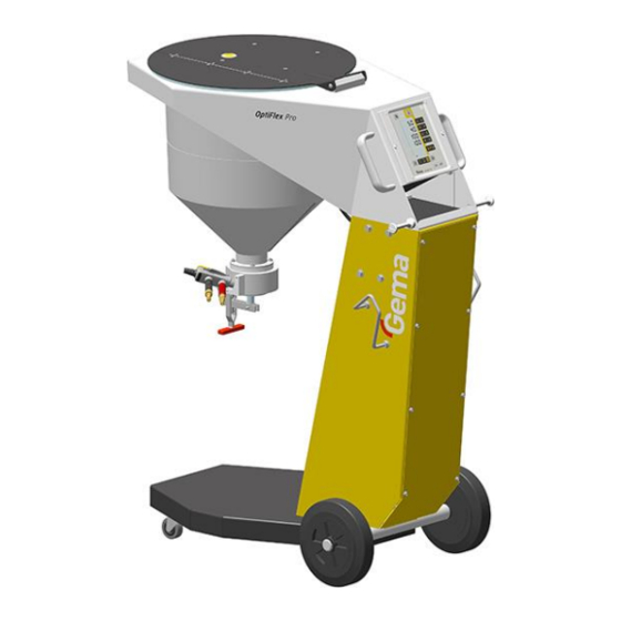
Manual equipment
OptiFlex Pro BN
This equipment was developed for use with electrically non-
conducting powders. The use of electrically conducting powders
(like metallic or graphite powders) can cause a permanent
decrease of functioning.
Translation of the original operating instructions
Advertisement
Table of Contents

Related Manuals for Gema OptiFlex Pro BN


Summary of Contents for Gema OptiFlex Pro BN
- Page 1 Rev. 01 1017 972 Operating instructions and Spare parts list Manual equipment OptiFlex Pro BN This equipment was developed for use with electrically non- conducting powders. The use of electrically conducting powders (like metallic or graphite powders) can cause a permanent decrease of functioning.
- Page 2 To the best of our knowledge and belief, the information contained in this publication was correct and valid on the date of publication. Gema Switzerland GmbH makes no representations or warranties with respect to the contents or use of this publication, and reserves the right to revise this publication and make changes to its content without prior notice.
-
Page 3: Table Of Contents
Basic conditions ..................25 Initial start-up ......................26 Setting the device type ..................26 Operation Operation ......................27 Select predefined operating mode (Preset mode) ........28 Starting the individual adjustable programs ..........28 Table of contents 3 OptiFlex Pro BN... - Page 4 Disposal regulations ................47 Materials ....................47 Spare parts list Ordering spare parts ..................... 49 OptiFlex Pro BN – Spare parts list ............... 50 OptiFlex Pro BN – Spare parts ................51 Stirrer hopper ......................52 Stirrer hopper – Spare parts ................. 53 Stirrer drive unit ....................
-
Page 5: About These Instructions
General information This operating manual contains all important information which you require for the working with the OptiFlex Pro BN. It will safely guide you through the start-up process and give you references and tips for the optimal use when working with your powder coating system. -
Page 6: Structure Of Safety Notes
Figure references in the text Figure references are used as cross references in the descriptive text. Example: "The high voltage (H) created in the gun cascade is guided through the center electrode." 6 About these instructions OptiFlex Pro BN... -
Page 7: Safety
If this product is to be used for other purposes or other substances outside of our guidelines then Gema Switzerland GmbH should be consulted. - Page 8 The use of other parts can lead to risk of injury. Only original Gema spare parts should be used! Repairs must only be carried out by specialists or by authorized Gema service centers. Unauthorized conversions and modifications can lead to injuries and damage to the equipment and invalidate the Gema Switzerland GmbH guarantee.
- Page 9 The control units for the spray guns must be installed and used in zone 22. Spray guns are allowed in zone 21. Only original Gema OEM parts are guaranteed to maintain the explosion protection rating. If damages occur by using spare parts from other...
- Page 10 Disconnect the plugs before the machines are opened for maintenance Disconnect from mains or repair. before maintenance works take place The plug connections between the powder spraying equipment and the mains should only be removed when the power supply is switched off. 10 Safety OptiFlex Pro BN...
- Page 11 The operating personnel must wear electrically conductive, steel-toe footwear (e.g. ESD shoes). The operating personnel should hold the gun with bare hands. If gloves are worn, these must also conduct electricity. Safety 11 OptiFlex Pro BN...
- Page 12 Rev. 01 08/20 12 Safety OptiFlex Pro BN...
-
Page 13: Product Description
Any other use is considered non-compliant. The manufacturer is not responsible for any incorrect use and the risks associated with such actions are assumed by the user alone! Product description 13 OptiFlex Pro BN... -
Page 14: Reasonably Foreseeable Misuse
All information about the OptiStar 4.0 (Type CG21) manual gun control unit can found in the documentation for that equipment (enclosed with this manual)! OptiFlow injector All information about the OptiFlow injector will be found in the corresponding enclosed documentation! 14 Product description OptiFlex Pro BN... -
Page 15: Scope Of Delivery
– Powder hopper with stirrer and cover, inclusive mains adaptor for the stirrer – Pneumatic hoses for conveying air (red) and fluidizing air (black) – Operating manual – Short description Product description 15 OptiFlex Pro BN... -
Page 16: Typical Characteristics - Properties Of The Functions
The type S manual coating equipment allows for powder to be processed directly out of the stirrer recipient. Because of the conical shape of the stirrer recipient, the powder can be used completely (optimum powder consumption). 16 Product description OptiFlex Pro BN... -
Page 17: Technical Data
Rev. 01 08/20 Technische Daten Technical Data Connectable guns OptiFlex Pro BN connectable OptiSelect Pro Type GM04 OptiSelect type GM03 yes* OptiGun GA03 yes** The PowerBoost functionality is not available. with trigger adapter ATTENTION The gun control unit may only be used with the specified gun... -
Page 18: Dimensions
Rev. 01 08/20 Dimensions OptiFlex Pro BN Width 481 mm Depth 822 mm Height 1109 mm Weight ca. 57 kg Processible powders OptiFlex Pro BN Powder containing Boron Nitride Metallic powder Graphite powder Enamel powder Environmental conditions OptiFlex Pro BN... -
Page 19: Rating Plate
Rev. 01 08/20 Rating plate fig. 4 Product description 19 OptiFlex Pro BN... - Page 20 Rev. 01 08/20 20 Product description OptiFlex Pro BN...
-
Page 21: Assembly / Connection
(such as an enameling furnace) or electromagnetic sources (such as a control cabinet). Assembly guide The manual coating equipment must be set up in accordance with the setup and connecting instructions (included with delivery). fig. 5 Assembly / Connection 21 OptiFlex Pro BN... -
Page 22: Connection Instructions
► Check ground connections with Ohm meter and ensure 1 MOhm or less! The compressed air must be free of oil and water! Close the unused connections with the provided dust protection caps! 22 Assembly / Connection OptiFlex Pro BN... -
Page 23: Adaptor For External Triggered Powder Guns (Boron Nitride Adapter)
Rev. 01 08/20 The powder hose Ø 12.5/9.5 mm (PUR) is to be used for hose lengths up to 12 m. ► For lengths beyond that, please contact Gema. Adaptor for external triggered powder guns (Boron Nitride Adapter) An OptiGun GA03 Automatic powder gun can be connected to a Gun control unit and externally triggered (by short-circuiting the two cables of the adaptor piece). - Page 24 Rev. 01 08/20 24 Assembly / Connection OptiFlex Pro BN...
-
Page 25: Start-Up
– Gun correctly connected – Gun control unit correctly connected – Corresponding power and compressed air supply available – Powder preparation and powder quality OK Start-up 25 OptiFlex Pro BN... -
Page 26: Initial Start-Up
ATTENTION A wrong parameterization leads to various malfunctions! ► For more on this, please also see the operating instructions for the gun control unit! 26 Start-up OptiFlex Pro BN... -
Page 27: Operation
► The manual equipment may only be operated in conjunction with a sufficiently powerful suction unit (such as Gema Classic Open booth). Fill the stirrer hopper with powder... -
Page 28: Select Predefined Operating Mode (Preset Mode)
Select the desired program (01-20) Program 20 active Change the coating parameters as required Programs 01-20 are preset at the factory but can be modified at any time, after which they are automatically stored. 28 Operation OptiFlex Pro BN... -
Page 29: Setting Powder Output And Powder Cloud
Adjust the total air volume on the gun control unit with the T3/T4 keys – Adjust the total air volume according to the corresponding coating requests correct powder cloud too little total air Setting the powder output Operation 29 OptiFlex Pro BN... -
Page 30: Setting The Electrode Rinsing Air
(deflector plate, flat jet nozzle) ≈ 0.1 Nm³/h ≈ 0.5 Nm³/h too much electrode rinsing air If in this display level is no operation for 3 seconds, the first display level is switched over independently. 30 Operation OptiFlex Pro BN... -
Page 31: Rinsing Mode
On manual coating equipment type F, the injector must be disconnected prior to cleaning procedure, on type B, the suction unit must be lifted, and on type S, the powder container must be empty. Detach the injector START = Operation 31 OptiFlex Pro BN... - Page 32 Manual equipment with optional PowerClean module (system parameter P01= 1 or P01=2) The rinsing mode can only be activated from standby mode (main menu display, no powder conveying). START = 32 Operation OptiFlex Pro BN...
- Page 33 Manual PowerClean impulse by pressing the gun trigger a (manual) second time STOP = OR the cleaning mode is terminated automatically. After completion of the PowerClean procedure, the controller switches back to coating mode. Operation 33 OptiFlex Pro BN...
-
Page 34: Setting The Background Illumination
Rev. 01 08/20 Setting the background illumination Press the The display switches to the following level: Select the desired brightness 34 Operation OptiFlex Pro BN... -
Page 35: Color Change
Dismantle and clean the powder gun (see therefore the user manual of the powder gun) Clean the injector (see therefore the injector user manual) 10. Prepare the manual coating equipment with new powder for start-up Operation 35 OptiFlex Pro BN... - Page 36 Rev. 01 08/20 36 Operation OptiFlex Pro BN...
-
Page 37: Decommissioning / Storage
If the physical conditions are maintained, the unit can be stored indefinitely. Space requirements The space requirements correspond to the size of the product. There are no special requirements concerning distance to neighboring equipment. Decommissioning / Storage 37 OptiFlex Pro BN... -
Page 38: Physical Requirements
Storage must be inside a dry building at a temperature between +5 and +50 °C. Do not expose to direct sunlight. Maintenance during storage Maintenance schedule No maintenance schedule is necessary. Maintenance works During long-term storage, periodically perform a visual check. 38 Decommissioning / Storage OptiFlex Pro BN... -
Page 39: Maintenance / Repairs
Weekly maintenance Clean stirrer hopper, injector, rinsing module** and powder gun. Check the control unit grounding connections to the coating booth, the suspension devices of the work pieces, or the conveyor chain Maintenance / Repairs 39 OptiFlex Pro BN... -
Page 40: Biannually Maintenance
The filter unit on the manual coating equipment measures and cleans the compressed air. This is where the equipment's main compressed air connection is located. Replacing the filter element Unscrew the filter glass on the filter unit Remove the complete filter element 40 Maintenance / Repairs OptiFlex Pro BN... - Page 41 Rev. 01 08/20 fig. 10 Replace the filter element Clean the filter glass on the inside and install it again Maintenance / Repairs 41 OptiFlex Pro BN...
-
Page 42: Cleaning
Clean the powder hose Reassemble the gun and connect it Cleaning the powder container Place an empty container under the discharge flap. Open the discharge flap by pushing the lever towards the column. 42 Maintenance / Repairs OptiFlex Pro BN... -
Page 43: Repair Work
Repair work In the event of malfunctions or faults, the product must be checked and repaired by an authorized Gema service workshop. The repairs must only be performed by an authorized specialist. Improper tampering can result in serious danger for user and equipment. - Page 44 Rev. 01 08/20 44 Maintenance / Repairs OptiFlex Pro BN...
-
Page 45: Fault Clearance
Injector or nozzle on the Clean the corresponding part gun trigger is pressed injector, powder hose or powder gun clogged Insert sleeve in the injector is Clean/replace clogged Fluidization not running see below Fault clearance 45 OptiFlex Pro BN... - Page 46 Fluidizing air is set too low on Set the fluidizing air correctly the control unit Throttle motor defective Contact local Gema representative Motor/condenser broken Contact local Gema Stirrer motor not functioning representative Motor cable not plugged in plug in 46 Fault clearance OptiFlex Pro BN...
-
Page 47: Disposal
Requirements on personnel carrying out the work The disposal of the product is to be carried out by the owner or operator. When disposing of components that are not manufactured by Gema, the instructions in the respective manufacturer’s documentation must be observed. - Page 48 Rev. 01 08/20 48 Disposal OptiFlex Pro BN...
-
Page 49: Spare Parts List
When using the spare parts from other manufacturers the explosion protection is no longer guaranteed. If any damage is caused by this use all guarantee claims become invalid! ► Only original Gema spare parts should be used! Spare parts list 49 OptiFlex Pro BN... -
Page 50: Optiflex Pro Bn - Spare Parts List
Rev. 01 08/20 OptiFlex Pro BN – Spare parts list OptiStar CG21 gun control unit – complete (see corresponding operating manual) OptiGun GA03 automatic powder gun – complete (see corresponding user manual) OptiSelect Pro GM04 Manual powder gun – complete (see corresponding user manual) OptiFlow IG06-BN injector –... -
Page 51: Optiflex Pro Bn - Spare Parts
Rev. 01 08/20 OptiFlex Pro BN – Spare parts fig. 11: Spare parts list 51 OptiFlex Pro BN... -
Page 52: Stirrer Hopper
Cylinder ribbed Allen screw – M6x16 mm 261 823 Cylinder ribbed Allen screw – M5x12 mm 257 052 Guide ring 380 318# Stirrer brush 377 660# * Please indicate length # Wearing part 52 Spare parts list OptiFlex Pro BN... -
Page 53: Stirrer Hopper - Spare Parts
Rev. 01 08/20 Stirrer hopper – Spare parts fig. 12: Stirrer hopper – Spare parts Spare parts list 53 OptiFlex Pro BN... -
Page 54: Stirrer Drive Unit
Shake proof washer 205 885 Fuse – 2 AT 221 872 Adaptor cable for stirrer connection 391 905 Gland 265 780 Gasket for stirrer motor 393 924 * Please indicate length # Wearing part 54 Spare parts list OptiFlex Pro BN... -
Page 55: Stirrer Drive Unit - Spare Parts
Rev. 01 08/20 Stirrer drive unit – Spare parts fig. 13: Stirrer drive unit – Spare parts Spare parts list 55 OptiFlex Pro BN... -
Page 56: Pneumatic Group
Pressure gauge – 0-10 bar, 1/8" 1008 049 Distribution block 1017 816 Screw-in nipple – 1/4", Ø 8 mm 265 136 Plug – Ø 8 mm 238 023 # Wearing part fig. 14: Pneumatic group 56 Spare parts list OptiFlex Pro BN... - Page 57 Rev. 01 08/20 Spare parts list 57 OptiFlex Pro BN...
- Page 59 Shutdown ............37 Sound pressure level ........18 Fault clearance ..........45 Spare parts list ..........49 Figure references in the text ......6 Start-up ............25 Storage ............37 Intended use ............ 13 Index 59 OptiFlex Pro BN...
- Page 60 Rev. 01...
Need help?
Do you have a question about the OptiFlex Pro BN and is the answer not in the manual?
Questions and answers