Gema OptiFlex Pro B Operating Instructions And Spare Parts List
Manual equipment
Hide thumbs
Also See for OptiFlex Pro B:
- Quick reference manual (90 pages) ,
- Quick reference manual (32 pages)

Related Manuals for Gema OptiFlex Pro B


Summary of Contents for Gema OptiFlex Pro B
- Page 1 Rev. 00 1017 931 Operating instructions and Spare parts list Manual equipment OptiFlex Pro B Translation of the original operating instructions...
- Page 2 To the best of our knowledge and belief, the information contained in this publication was correct and valid on the date of publication. Gema Switzerland GmbH makes no representations or warranties with respect to the contents or use of this publication, and reserves the right to revise this publication and make changes to its content without prior notice.
-
Page 3: Table Of Contents
Assembly guide ..................... 23 Connection instructions ..................24 Set head piece ...................... 25 Start-up Preparation for start-up ..................27 Basic conditions ..................27 Initial start-up ......................28 Setting the device type ..................28 Table of contents 3 OptiFlex Pro B... - Page 4 Disposal regulations ................47 Materials ....................47 Spare parts list Ordering spare parts ..................... 49 OptiFlex Pro B – Spare parts list ................50 OptiFlex Pro B – Spare parts ................51 Fluidizing/suction unit ................... 52 Fluidizing/suction tube – spare parts ..............53 Pneumatic group ....................
- Page 5 Rev. 00 03/19 Table of contents 5 OptiFlex Pro B...
-
Page 7: About These Instructions
General information This operating manual contains all important information which you require for the working with the OptiFlex Pro B. It will safely guide you through the start-up process and give you references and tips for the optimal use when working with your powder coating system. -
Page 8: Structure Of Safety Notes
Figure references in the text Figure references are used as cross references in the descriptive text. Example: "The high voltage (H) created in the gun cascade is guided through the center electrode." 8 About these instructions OptiFlex Pro B... -
Page 9: Safety
If this product is to be used for other purposes or other substances outside of our guidelines then Gema Switzerland GmbH should be consulted. -
Page 10: Product Specific Security Regulations
If this product is to be used for other purposes or other substances outside of our guidelines then Gema Switzerland GmbH should be consulted. - Page 11 The use of other parts can lead to risk of injury. Only original Gema spare parts should be used! Repairs must only be carried out by specialists or by authorized Gema service centers. Unauthorized conversions and modifications can lead to injuries and damage to the equipment and invalidate the Gema Switzerland GmbH guarantee.
- Page 12 As a general rule for all powder spraying installations, persons with The stay for persons pacemakers should never enter high voltage areas or areas with with cardiac pacemakers electromagnetic fields. Persons with pacemakers should not enter areas is forbidden with powder spraying installations! 12 Safety OptiFlex Pro B...
- Page 13 The operating personnel must wear electrically conductive, steel-toe footwear (e.g. leather soles). The operating personnel should hold the gun with bare hands. If gloves are worn, these must also conduct electricity. Safety 13 OptiFlex Pro B...
- Page 14 Rev. 00 03/19 14 Safety OptiFlex Pro B...
-
Page 15: Product Description
Any other use is considered non-compliant. The manufacturer is not responsible for any incorrect use and the risks associated with such actions are assumed by the user alone! Product description 15 OptiFlex Pro B... -
Page 16: Reasonably Foreseeable Misuse
All information about the OptiStar 4.0 (Type CG21) manual gun control unit can found in the documentation for that equipment (enclosed with this manual)! OptiFlow injector All information about the OptiFlow injector will be found in the corresponding enclosed documentation! 16 Product description OptiFlex Pro B... -
Page 17: Scope Of Delivery
In moist or tropical environments, any moisture is driven from the injector, powder hose and powder gun. The color change is also accelerated during non-extreme color switches. Product description 17 OptiFlex Pro B... - Page 18 Rev. 00 03/19 fig. 4 18 Product description OptiFlex Pro B...
-
Page 19: Technical Data
Rev. 00 03/19 Technische Daten Technical Data Connectable guns OptiFlex Pro B connectable OptiSelect Pro Type GM04 OptiSelect type GM03 yes* TriboJet yes** The PowderBoost functionality is not available The gun type must be configured (refer to chapter "Additional functions"). The Tribo gun the gun is not type approved (ATEX). -
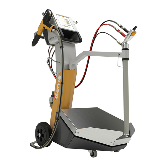
Page 20: Dimensions
Rev. 00 03/19 Dimensions OptiFlex Pro B Width 481 mm Depth 822 mm Height 1109 mm Weight ca. 43 kg Processible powders OptiFlex Pro B Plastic powder Metallic powder Enamel powder Powder output (reference values) General conditions for the OptiFlow Injector... -
Page 21: Air Flow Rates
The total air consists of conveying air and supplementary air, in relation to the selected powder quantity (in %). As a result the total air volume is maintained constant. Factory OptiFlex Pro B Range setting Flow rate – fluidizing air: –... -
Page 22: Sound Pressure Level
Rev. 00 03/19 Sound pressure level OptiFlex Pro B Normal operation < 60 dB(A) The sound pressure level was measured while the unit was in operation; measurements were taken at the most frequent operator positions and at a height of 1.7 m from the ground. -
Page 23: Assembly / Connection
(such as an enameling furnace) or electromagnetic sources (such as a control cabinet). Assembly guide The manual coating equipment must be set up in accordance with the setup and connecting instructions (included with delivery). fig. 6 Assembly / Connection 23 OptiFlex Pro B... -
Page 24: Connection Instructions
Check ground connections with Ohm meter and ensure 1 MOhm or less. The compressed air must be free of oil and water! Close the unused connections with the provided dust protection caps! 24 Assembly / Connection OptiFlex Pro B... -
Page 25: Set Head Piece
Rev. 00 03/19 Set head piece Assembly / Connection 25 OptiFlex Pro B... - Page 26 Rev. 00 03/19 26 Assembly / Connection OptiFlex Pro B...
-
Page 27: Start-Up
– Gun correctly connected – Gun control unit correctly connected – Corresponding power and compressed air supply available – Powder preparation and powder quality OK Start-up 27 OptiFlex Pro B... -
Page 28: Initial Start-Up
WARNING: A wrong parameterization leads to various malfunctions! ► For more on this, please also see the operating instructions for the OptiStar CGxx gun control unit! 28 Start-up OptiFlex Pro B... -
Page 29: Operation
► The manual equipment may only be operated in conjunction with a sufficiently powerful suction unit (such as Gema Classic Open booth). Swivel aside the fluidizing/suction unit... -
Page 30: Select Predefined Operating Mode (Preset Mode)
60 % Total air 4.0 Nm³/h High voltage 80 kV Spray current 20 µA Electrode rinsing air 0.1 Nm³/h Fluidizing air 1.0 Nm³/h (for device type F) 0.1 Nm³/h (for device type B and S) 30 Operation OptiFlex Pro B... -
Page 31: Setting Powder Output And Powder Cloud
– Adjust the total air volume according to the corresponding coating requests correct powder cloud too little total air Setting the powder output much powder little powder Adjust the powder output volume (e.g. according to the desired coating thickness) Operation 31 OptiFlex Pro B... -
Page 32: Setting The Electrode Rinsing Air
(deflector plate, flat jet nozzle) ≈ 0.1 Nm³/h ≈ 0.5 Nm³/h too much electrode rinsing air If in this display level is no operation for 3 seconds, the first display level is switched over independently. 32 Operation OptiFlex Pro B... -
Page 33: Rinsing Mode
On manual coating equipment type F, the injector must be disconnected prior to cleaning procedure, on type B, the suction unit must be lifted, and on type S, the powder container must be empty. Detach the injector START = Operation 33 OptiFlex Pro B... - Page 34 Manual equipment with optional PowerClean module (system parameter P01= 1 or P01=2) The rinsing mode can only be activated from standby mode (main menu display, no powder conveying). START = 34 Operation OptiFlex Pro B...
- Page 35 Manual PowerClean impulse by pressing the gun trigger a (manual) second time STOP = OR the cleaning mode is terminated automatically. After completion of the PowerClean procedure, the controller switches back to coating mode. Operation 35 OptiFlex Pro B...
-
Page 36: Setting The Background Illumination
Rev. 00 03/19 Setting the background illumination Press the The display switches to the following level: Select the desired brightness 36 Operation OptiFlex Pro B... -
Page 37: Color Change
Clean the injector (see therefore the injector user manual) 10. Remove the swivel arm and blow off with a compressed air gun 11. Prepare the manual coating equipment with new powder for start-up Operation 37 OptiFlex Pro B... - Page 38 Rev. 00 03/19 38 Operation OptiFlex Pro B...
-
Page 39: Decommissioning / Storage
If the physical conditions are maintained, the unit can be stored indefinitely. Space requirements The space requirements correspond to the size of the product. There are no special requirements concerning distance to neighboring equipment. Decommissioning / Storage 39 OptiFlex Pro B... -
Page 40: Physical Requirements
Storage must be inside a dry building at a temperature between +5 and +50 °C. Do not expose to direct sunlight. Maintenance during storage Maintenance schedule No maintenance schedule is necessary. Maintenance works During long-term storage, periodically perform a visual check. 40 Decommissioning / Storage OptiFlex Pro B... -
Page 41: Maintenance / Repairs
Place the fluidizing/suction unit back into the powder shortly before restarting operation Check the control unit grounding connections to the coating booth, the suspension devices of the work pieces, or the conveyor chain Maintenance / Repairs 41 OptiFlex Pro B... -
Page 42: If In Disuse For Several Days
Replacing the filter element Unscrew the filter glass on the filter unit Remove the complete filter element fig. 9 Replace the filter element Clean the filter glass on the inside and install it again 42 Maintenance / Repairs OptiFlex Pro B... -
Page 43: Cleaning
Clean the integrated gun tube with the brush supplied if necessary Blow through the gun with compressed air again Clean the powder hose Reassemble the gun and connect it Maintenance / Repairs 43 OptiFlex Pro B... -
Page 44: Cleaning The Fluidizing/Suction Unit
Repair work In the event of malfunctions or faults, the product must be checked and repaired by an authorized Gema service workshop. The repairs must only be performed by an authorized specialist. Improper tampering can result in serious danger for user and equipment. -
Page 45: Fault Clearance
Injector or nozzle on the Clean the corresponding part gun trigger is pressed injector, powder hose or powder gun clogged Insert sleeve in the injector is Clean/replace clogged Fluidization not running see below Fault clearance 45 OptiFlex Pro B... - Page 46 Contact local Gema Vibrator not functioning representative Vibrator not plugged in plug in Incorrect equipment type Configure parameter P00 (See configured operating instructions for the manual gun control unit, Chapter "Start-up – Setting Equipment Type") 46 Fault clearance OptiFlex Pro B...
-
Page 47: Disposal
Requirements on personnel carrying out the work The disposal of the product is to be carried out by the owner or operator. When disposing of components that are not manufactured by Gema, the instructions in the respective manufacturer’s documentation must be observed. - Page 48 Rev. 00 03/19 48 Disposal OptiFlex Pro B...
-
Page 49: Spare Parts List
When using the spare parts from other manufacturers the explosion protection is no longer guaranteed. If any damage is caused by this use all guarantee claims become invalid! ► Only original Gema spare parts should be used! Spare parts list 49 OptiFlex Pro B... -
Page 50: Optiflex Pro B - Spare Parts List
Rev. 00 03/19 OptiFlex Pro B – Spare parts list OptiStar CG21 gun control unit – complete (see corresponding operating manual) OptiSelect Pro GM04 Manual powder gun – complete (see corresponding user manual) OptiFlow IG07 injector – complete (see corresponding user manual) Pneumatic connection for supplementary air –... -
Page 51: Optiflex Pro B - Spare Parts
Rev. 00 03/19 OptiFlex Pro B – Spare parts fig. 10: Spare parts list 51 OptiFlex Pro B... -
Page 52: Fluidizing/Suction Unit
Quick release connection – NW5, Ø 6 mm 200 840 Nut with kink protection – M10x1 mm, Ø 6 mm 201 308 Plastic tube – Ø 6/4 mm, black 1001 973 * Please indicate length # Wearing part 52 Spare parts list OptiFlex Pro B... -
Page 53: Fluidizing/Suction Tube - Spare Parts
Rev. 00 03/19 Fluidizing/suction tube – spare parts fig. 11: Fluidizing/suction tube – spare parts Spare parts list 53 OptiFlex Pro B... -
Page 54: Pneumatic Group
Pressure gauge – 0-10 bar, 1/8" 1008 049 Distribution block 1017 816 Screw-in nipple – 1/4", Ø 8 mm 265 136 Plug – Ø 8 mm 238 023 # Wearing part fig. 12: Pneumatic group 54 Spare parts list OptiFlex Pro B... -
Page 55: Powerclean Module Set
Plastic tube – Ø 8/6 mm, black 103 152* O ring – Ø 16x2 mm, NBR70, anti-static (2x) (not shown) Cable tie (not shown) * Please indicate length # Wearing part fig. 13: PowerClean module set** Spare parts list 55 OptiFlex Pro B... - Page 57 Fault clearance ..........45 Safety symbols ..........7 Figure references in the text ......8 Sound pressure level ........22 Spare parts list ..........49 Start-up ............27 Storage ............39 Intended use ............ 15 Index 57 OptiFlex Pro B...
- Page 58 Rev. 00...
Need help?
Do you have a question about the OptiFlex Pro B and is the answer not in the manual?
Questions and answers