
Related Manuals for Carrier TRANSICOLD Vector 1550


Summary of Contents for Carrier TRANSICOLD Vector 1550
- Page 1 Trailer & Rail Refrigeration Vector 1550 Trailer Refrigeration Units Operator Manual 62-12113...
- Page 3 Vector 1550 Trailer Refrigeration Units Operator Manual © 2019 Carrier Corporation Printed in U. S. A. March 2019 ●...
-
Page 5: Table Of Contents
Table of Contents 1. Introduction ................1 2. Unit Identification ..............2 3. Safety .................. 3 3.1 Auto-Start ................3 3.2 Cooling System ..............3 3.3 Refrigerant ................4 3.4 Battery ................4 3.5 Standby Electric Power ............4 4. Display ................. 5 4.1 Display Screens .............. -
Page 7: Introduction
When having this unit serviced, be sure to specify genuine Carrier Transicold replacement parts for the highest quality and best reliability. At Carrier Transicold, we are continually working to improve the products that we build for our customers. As a result, specifications may change without notice. -
Page 8: Unit Identification
2. Unit Identification Each unit is identified by a decal attached to the frame of the unit inside the roadside side door. This decal is on the bottom vertical frame next to the display. The decal identifies the model number of the unit, the warranty ID number, the serial number, the type of refrigerant and refrigerant charge. -
Page 9: Safety
This Carrier Transicold refrigeration unit has been designed with the safety of the operator in mind. During normal operation, all moving parts are fully enclosed to help prevent injury. During any inspection or servicing with the doors open you may be exposed to moving parts, please stay clear of all moving parts when the unit is in operation. -
Page 10: Refrigerant
For this reason (and because of legislation regarding the handling of refrigerants) we recommend that you contact your nearest Carrier Transicold authorized repair facility whenever service of the refrigerant system is required. 3.4 Battery This unit may be equipped with a lead-acid type battery. -
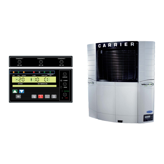
Page 11: Display
4. Display Figure 3 - Display Screens 62-12113... -
Page 12: Display Screens
4.1 Display Screens 4.1.1 Display 1. Not used on 1550 units 2. Mode lights 3. Display NOTE: Box temperature is displayed in °C or °F (depending on configuration). 4. Up and down arrow keys 9. Start/stop-continuous key 5. Equal key 10. - Page 13 4.1.3 Starting the Unit - Road Operation To power up the unit, place the ENGINE / STANDBY switch (12) to ENGINE. Place the Run/Stop switch (11) on the microprocessor controller to 3. Toggle the LANGUAGE switch (13) to select one of the available languages.
- Page 14 For safe, reliable operation in Electric operation, it is important to consider the following guidelines: • NEVER connect the unit to a high voltage power source unless the START/RUN - OFF switch is in the OFF position. • The power supply cable and circuit breaker must comply with local electrical code and unit specifications.
- Page 15 until the operating mode Press the SELECT key appears in the Message center. Press UP or DOWN ( Opti arrow to select COLD, EcoFUEL or customized. to validate selected Press the EQUAL key configuration. 4.1.7 Initiating Defrost Mode The defrost mode may be initiated in three different ways if the evaporator coil is below 4.5°C (40°F): 1.
- Page 16 4.1.8 Changing Setpoint Temperature ) or DOWN ( 1. With the set point displayed, press the UP ( ARROW key to change setpoint to the desired value. The display will flash to indicate that the set point reading being displayed is a non-entered value.
- Page 17 The shut-down time is pre- programmed in the plant. The user should determine whether this setting is appropriate for his type of cargo and the insulation of the bodywork (all adjustments are to be made by a Carrier Transicold technician). 62-12113...
- Page 18 During unit shut-downs, the evaporator fans also stop. Only use this operating mode for products which tolerate shut-downs of this kind. Devices which ensure it operates correctly. These check: - the battery status - the temperature of the engine water - the minimum run time Automatic start/stop is provided to permit starting/restarting of the ...
- Page 19 4.1.11 Continuous Run Operation 1. Press the START/STOP CONTINUOUS key ( ) until the CONTINUOUS RUN Light (2.) on the controller illuminates. 2. Verify that "CONTINUOUS RUN MODE SELECTED" is displayed on the message center and that the CONTINUOUS RUN Light is illuminated.
- Page 20 4.1.13 Trip Start Trip Start marks a time stamp in memory to allow easy review of the data from the last trip. This function tells the recorder that the present date and time is beginning of a new trip. 1. To mark the start of a trip in the data recorder, press the SELECT key ) until "PRESS = TO MARK TRIP START"...
- Page 21 4.1.15 Changing a Function (continued) 5. To change one of the Functions, bring the Function you wish to change into the Message Cener and press the EQUAL ( "TO SCROLL, THEN = TO SAVE" will appear in the Message center. 6.
- Page 22 4.1.15 Changing a Function (continued) Unit problems detected by the controller are stored in the Alarm List in the controller. Stored alarms may be viewed in the Message center. The "STATUS OK" message will be displayed in the Message center. 1.
- Page 23 4.1.15.1 Alarm List (continued) 62-12113...
- Page 24 4.1.15.1 Alarm List (continued) 4.1.16 Operating with Auxiliary Control Panel 1. Start the unit as mentioned before. 2. Press the SYSTEM ON/OFF key (16). Power light will go ON. 3. Press the ON/OFF key (14) to energize selected compartment. 4. Display 62-12113...
- Page 25 4.1.16.1 Changing Setpoint Set point change can be made from control panel or cab control. Press the UP or DOWN ARROW key (19) to increase or decrease set point. This is the same operation for each compartment. 4.1.16.2 Setting Pre-Set Setpoint The control panel allows the user to pre-set five different temperatures on each compartmrnt.
- Page 26 4.1.16.3 Removing Pre-Set Setpoint Switch main RUN/STOP switch and required remote compartment switches on the unit to RUN. Press Carrier logo and the lock light will be displayed. Press host compartment up arrow for 10 seconds. P1 will be displayed in all compartments. Set temperature to lowest possible and OFF will be displayed.
-
Page 27: Pretrip Inspection
5. Pretrip Inspection The Pretrip Inspection should be performed before picking up any load. This inspection is essential to ensure reliable operation of this unit. These checks take only a few minutes. Unit may start automatically at any time even if switch is in the OFF position. - Page 28 5. Pretrip Inspection (continued) Immediately After Starting Engine Visually check fuel lines and filters for leaks Visually check oil lines and filters for leaks Visually check coolant hoses for leaks Visually check exhaust system for leaks Verify correct air flow of condenser fan* * Place a small rag in front of the condenser coil, the rag should hold.
-
Page 29: Maintenance
3. Check fuel heater (if equipped) Cooling 1. Check coolant change interval. If replacement is not required, check antifreeze concentration using a System refractometer (Carrier Transicold P/N 07-00435-00) 2. Clean condenser/radiator surfaces 3. Check water pump 4. Check water temperature sensor Exhaust 1. - Page 30 6.1 Maintenance Schedule (continued) Starting 1. Clean battery connections and cable ends Circuit 2. Check battery hold down clamps 3. Check battery condition 4. Check starter operation *Based on EPA 40 CFR Part 89 Every Service Interval or Yearly (Continued) Charging 1.
-
Page 31: Checking Oil Level
6.2 Checking Oil Level Engine oil - the petroleum oils recommended for use in this refrigeration unit must comply with the American Petroleum Institute's (API) Class CG or better rating. The only recommended synthetic oil is Mobil Delvac 1. The use of any oil that does not meet this rating may affect the warranty on the engine. -
Page 32: Priming Fuel System
6.3 Priming Fuel System The mechanical fuel lift pump is mounted on the engine next to the injection pump. This pump has a manual plunger for priming the fuel system when the fuel tank has been run dry. Keep clear of rotating belts and pulleys. Turn the bleed valve (red) counter-clockwise until fully opened. -
Page 33: Product Loading
7. Product Loading 7.1 Before Loading • Pre-cool the compartment. This will remove much of the heat from the inside of the compartment (including the walls and insulation) and give the product better protection when it is loaded. • If possible, place unit in a defrost cycle immediately before loading. This will remove moisture accumulated on the evaporator coil. - Page 34 7.2 During Loading (continued) Product stacking is another important factor in protecting the product. Products that generate heat - fruits and vegetables, for example - should be stacked so the air can flow through the product to remove the heat; this is called “air stacking” the product. Products that do not create heat - meats and frozen products - should be stacked tightly in the center of the trailer.
-
Page 35: Recommended Transport Temperatures
These are included for reference only and should not be considered pre-emptive of the setpoint required by the shipper or receiver. Contact your Carrier Transicold dealer for more detailed information. Setpoint Range Product Operation 1 °F... -
Page 36: General Troubleshooting
If, however you are having an issue, the following section may be of assistance. If you do not find the trouble that you have experienced listed, please call your Carrier Transicold dealer for assistance. 62-12113... - Page 37 9. General Troubleshooting (continued) Engine Operation Check alarm list Visually check battery condition Unit won’t crank Visually check battery connections Check all fuses Check alarm list Unit won’t Check fuel level start Check all fuses Check alarm list Check fuel level Unit won't Check engine oil level Check all fuses...
-
Page 38: Fuses
10. Fuses Fuses are located in the in the Control Box (roadside of the unit). Unit may start automatically at any time even if the switch is in the OFF position. Use proper lockout/tagout procedures before inspection/servicing. All unit inspection/servicing by properly trained personnel only. -
Page 39: Emergency Road Service
11. Emergency Road Service At Carrier Transicold we’re working hard to give you complete service when and where you need it. That means a worldwide network of dealers that offer 24-hour emergency service. These service centers are manned by factory trained service personnel and backed by extensive parts inventories that will assure you of prompt repair. - Page 42 Do not idle the engine except as necessary. For more information, go to www.P65warnings.ca.gov/diesel North America Central America and Mexico Carrier Transicold Carrier Transicold 700 Olympic Drive Ejercito Nacional 253-A Piso 5 Athens, GA 30601 USA Colonia Anahuac Tel: 1-706-357-7223 11320 Mexico, D.F.
Need help?
Do you have a question about the Vector 1550 and is the answer not in the manual?
Questions and answers