
Subscribe to Our Youtube Channel
Related Manuals for Carrier TRANSICOLD 69NT40-511-200


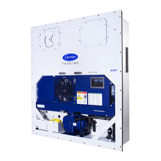
Summary of Contents for Carrier TRANSICOLD 69NT40-511-200
- Page 1 Container Refrigeration Unit Models 69NT40-511-200 69NT40-511-299 T-294 Rev A Downloaded from ManualsNet.com search engine...
- Page 2 OPERATION AND SERVICE MANUAL CONTAINER REFRIGERATION UNIT MODELS 69NT40-511-200 69NT40-511-299 Carrier Transicold Division, Carrier Corporation, P.O. Box 4805, Syracuse, N.Y. 13221 E Carrier Corporation 2000 S Printed in U. S. A. 0200 Downloaded from ManualsNet.com search engine...
-
Page 3: Safety Summary
SAFETY SUMMARY GENERAL SAFETY NOTICES The following general safety notices supplement the specific warnings and cautions appearing elsewhere in this manual. They are recommended precautions that must be understood and applied during operation and maintenance of the equipment covered herein. The general safety notices are presented in the following three sections labeled: First Aid, Operating Precautions and Maintenance Precautions. -
Page 4: Specific Warning And Caution Statements
SPECIFIC WARNING AND CAUTION STATEMENTS To help identify the label hazards on the Unit and explain the level of awareness each one carries, an explanation is given with the appropriate consequences: DANGER - - means an immediate hazard which WILL result in severe personal injury or death. WARNING - - means to warn against hazards or unsafe conditions which COULD result in severe personal injury or death. -
Page 5: Table Of Contents
TABLE OF CONTENTS Section Page SAFETY SUMMARY ............Safety-1 GENERAL SAFETY NOTICES . - Page 6 TABLE OF CONTENTS (CONTINUED) Section Page PRE-TRIP DIAGNOSTICS ......... . . 3-17 3.2.1 Pre-Trip...
- Page 7 TABLE OF CONTENTS (CONTINUED) Section Page TROUBLESHOOTING ........... . . UNIT WILL NOT START OR STARTS THEN STOPS .
- Page 8 TABLE OF CONTENTS (CONTINUED) Section Page 6.16 EVAPORATOR FAN AND MOTOR ASSEMBLY ......6-16 6.17 EVAPORATOR FAN MOTOR CAPACITORS .
- Page 9 LIST OF ILLUSTRATIONS (CONTINUED) Figure Page Figure 3-1 Micro-Link 2i Controller/DataCORDER Module ..... Figure 3-2 Key Pad ............Figure 3-3 Display Module .
- Page 10 LIST OF ILLUSTRATIONS (CONTINUED) Figure Page Figure 6-26 Stepper Motor Suction Modulation Valve (SMV) ....6-22 Figure 6-27 Jumper Assembly ..........6-24 Figure 6-28 Hermetic Thermostatic Expansion Valve Bulb .
-
Page 11: Introduction
The control Beginning with early 1995 production, in system automatically selects cooling, holding or addition to a model number, Carrier Transicold heating as necessary to maintain the desired began using a parts identification (PID) number temperature within the container. -
Page 12: Table 1-1 Model Chart
Table 1-1. Model Chart Schematic & Diagra MODEL MODEL NT0448 77-01698-38 69NT40 511 201 69NT40-511-201 NT0569 77-01698-60 69NT40-511-201 NT0602 77-01698-60 A = Factory Installed Pressure Gauges B = Factory Installed Pressure Transducers P = Provision X = Features that apply to model -- = Features that are not applicable to model T-294-01 Downloaded from... -
Page 13: Description
SECTION 2 DESCRIPTION 2.1 GENERAL DESCRIPTION the following sections in 2.1. The upper access panels allow front entry into the evaporator section, and the a. Refrigeration Unit - - Front Section center access panel allows access to the evaporator coil The front section of the refrigeration unit shows access heaters. - Page 14 b. Evaporator Section When transporting perishable (chilled) commodities, the fan motors will normally be in high speed above - -10_C (+14_F), or - -5_C (+23_F) optionally. The evaporator section (see Figure 2-2) contains the return temperature sensor (RTS), hermetic thermostatic The evaporator coil heaters are accessible by removing expansion valve, dual-speed evaporator fan motors the front lower access panel.
-
Page 15: Figure 2-2 Evaporator Section
(RRS) (RTS) 1. Evaporator Fan Motor #1 (EM1) 10. Evaporator Coil Heaters 2. Humidity Sensor (HS) -- Optional 11. Hermetic Thermostatic Expansion Valve 3. Return Temperature Sensor (RTS) 12. Drain Pan Heater (DPH) 4. Return Recorder Sensor (RRS) -- Optional 13. -
Page 16: Figure 2-3 Compressor Section
c. Compressor Section modulation valve (SMV), quench expansion valve, stepper motor drive (SD), and the discharge pressure The compressor section includes the compressor (with regulator valve. high pressure switch), power cable storage compartment, and autotransformer (TRANS), which is The supply temperature sensor (STS), and ambient located to the left of the compressor. -
Page 17: Figure 2-4 Condenser Section
d. Condenser Section condenser coil. When the unit is operating, air is pulled in the bottom of the coil and discharged horizontally out The condensing section consists of a condenser fan through the front of the condenser fan grille. motor (CM), a condenser fan and an air-cooled 1. -
Page 18: Water-Cooled Condenser
e. Water-Cooled Condenser Section condenser pressure transducer (CPT), filter-drier, water hook-up couplings, water pressure switch (WP), and the The water-cooled condenser section consists of liquid line process tube water-cooled condenser, sight glass, and rupture disc, 1. Water-Cooled Condenser 6. Coupling (Water In) 2. -
Page 19: Figure 2-6 Control Box Section
f. Control Box Section transformer (TR), fuses (F), key pad (KP), display module, current sensor module (CS), The control box (see Figure 2-6) includes the manual Controller/DataCORDER module, and an optional switches (ST and MDS), circuit breaker (CB-1), remote monitoring unit (CI). contactors (CF, CH, EF, ES and HR), hour meter (HM), 1. -
Page 20: Refrigeration System Data
2.2 REFRIGERATION SYSTEM DATA Number of Cylinders Model 06DR Weight (Dry) 118 kg (260 lb) a Compressor/Motor Assembly a. Compressor/Motor Assembly Approved Oil Castrol Icematic -- SW20 (CP) (CP) Oil Charge 3.6 liters (7.6 U.S. pints) The oil level range, with the compressor off, should be between the bottom and one-eighth Oil Sight Glass level of the capacity of the sight glass. -
Page 21: Electrical Data
2.3 ELECTRICAL DATA CB-1 Trips at 29 amps a. Circuit Breaker it B CB-2 (50 amp) Trips at 62.5 amps (CB) (CB) CB-2 (70 amp) Trips at 87.5 amps b. Compressor 17.6 amps @ 460 vac Full Load Amps (FLA) Motor (CP) (with current limiting set at 21 amps) 380 vac, Single Phase,... -
Page 22: Power Autotransformer (Trans)
Orange wire Power Red wire Output Brown wire Ground Input voltage 5 vdc Output voltage 0 to 3.3 vdc i. Humidity Sensor i. Humidity Sensor (HS) - - Optional Output voltage readings verses relative humidity (RH) percentage: 0.99 V 1.65 V 2.31 V 2.97 V 2.4 POWER AUTOTRANSFORMER (TRANS) -
Page 23: Refrigeration Circuit With The Water-Cooled Condenser
2.5 REFRIGERATION CIRCUIT WITH THE will open to de-energize the condenser fan relay, WATER-COOLED CONDENSER unless overridden by the out-of-range lockout feature (if so equipped). The condenser fan motor Starting at the compressor, the suction gas is will stop and will remain stopped until the water compressed to a higher temperature and pressure. -
Page 24: Figure 2-8 Refrigeration Circuit With Water-Cooled Condenser
1. High Pressure Switch 9. Rupture Disc 2. Discharge Pressure Regulator Valve 10. Moisture-Liquid Indicator 3. Air-Cooled Condenser 11. Condenser Pressure Transducer (CPT) 4. Evaporator 12. Filter-Drier 5. Hermetic Thermostatic Expansion Valve 13. Water-Cooled Condenser 6. External Equalizer Line 14. Stepper Motor Suction Modulation Valve (SMV) 7. -
Page 25: Upper Fresh Air Makeup Vent
2.7 UPPER FRESH AIR MAKEUP VENT 2.8 LOWER FRESH AIR MAKEUP VENT (Optional) The purpose of the upper fresh air makeup vent is to provide ventilation for commodities that require fresh The purpose of the lower fresh air makeup vent is to air circulation. -
Page 26: Remote Monitoring (Rm) -- Optional
2.9 REMOTE MONITORING (RM) - - Optional 2.10 SAFETY AND PROTECTIVE DEVICES NOTE Unit components are protected from damage by safety and protective devices listed in Table 2-1. These The in-range light will be illuminated if the devices monitor the unit operating conditions and open container control air temperature is within the a set of electrical contacts when an unsafe condition tolerance selected. -
Page 27: Microprocessor
SECTION 3 MICROPROCESSOR 3.1 MICRO-LINK 2i CONTROLLER MODULE 1. Mounting Screw 5. Fuses (F) 2. Micro-Link 2i 6. Control Circuit Power Connection Controller/DataCORDER Module (Location: In back of connector) 3. Connectors 7. Battery Pack (Optional) 4. Test Points (TP) 8. Software Programming Port Figure 3-1. -
Page 28: Controller Programming (Memory) Cards
3.1.2 Controller Programming (Memory) Cards Programming cards with either Operational Software or Configuration Software are available through CTD The programming cards are used for loading software Replacement Components Group. into the Controller. This is the same concept as using a floppy diskette to load software into a personal computer. -
Page 29: Table 3-1 Controller Configuration Variables
Table 3-1. Controller Configuration Variables CONFIGURATION TITLE DEFAULT OPTION NUMBER Bypass Valve Enable Evaporator Fan Speed dS (Dual) SS (Single) Number of Sensor Probes FOUr duAL Dehumidification Mode Probe Calibration nOCAL Condenser Fan Speed Select OFF (Single) On (Variable) Unit Selection, 20FT/ 40FT/45FT 40ft 20ft,45 Single Phase/Three Phase Motor... -
Page 30: Pre-Trip
3.1.3 General Layout of the Controller Section Table 3-2. Key Pad Function The Micro-Link 2i Controller/DataCORDER consists FUNCTION of a key pad, display module and Controller module. Change set point upward. Change Connectors are used to attach the wiring of the unit to codes upward. -
Page 31: Figure 3-3 Display Module
The display module (see Figure 3-3) is mounted at a 20 degree downward tilt to aid in visibility. The display module consists of: COOL HEAT DEFROST IN RANGE ALARM SUPPLY RETURN a. Two 25mm (1 inch) high, five digit LCD displays which are easily viewed in direct sunlight and backlighted for superior low-light visibility. -
Page 32: Controller Function Codes
Shows state of the solenoid quench valve, if so equipped (open or closed). (Open--Closed) Cd03 Not Applicable This code is not in use starting with model number 69NT40-511-200 and UP. Unit current is monitored by two current sensors. The current measured is used Line Current, for control and diagnostic purposes.For control processing, the highest of the... - Page 33 Code TITLE DESCRIPTION Inapplicable Functions Display -- -- -- -- -- Compressor discharge pressure is displayed using a pressure transducer. Compressor Pressure is displayed in units of psig when function code Cd28 is set to _F and Cd14 Discharge Pressure units of bars when Cd28 is set to _C.
- Page 34 Code TITLE DESCRIPTION Inapplicable Functions Display -- -- -- -- -- Display/Select Functions NOTE Function codes Cd27 through Cd37 are user-selectable functions. The operator can change the value of these functions to meet the operational needs of the container. The defrost interval is the time interval between defrost cycles. Five selectable values are available: 3, 6, 9, 12 or 24 hours.
- Page 35 Code TITLE DESCRIPTION Inapplicable Functions Display -- -- -- -- -- The current limit is the maximum current demand allowed on any phase at any time. Limiting the unit’s current (amperage) reduces the load on the main power and lowers the compressor discharge pressure. When desirable, the limit can be Current Limit Cd32 lowered.
-
Page 36: Controller Alarms
Code TITLE DESCRIPTION Inapplicable Functions Display -- -- -- -- -- This code is only applicable to units without a DataCORDER, that are configured Secondary Return to have four probes. If this is true, it will then display the current secondary return Cd39 Air Temperature air temperature.If the unit is configured with a DataCORDER, the Controller... -
Page 37: Table 3-4 Controller Alarm Indications
Table 3-4. Controller Alarm Indications Code TITLE DESCRIPTION Control Circuit Fuse Alarm 20 is triggered by fuse (F3) opening and will cause the software shutdown AL20 Open (24 vac) of all control units. This alarm will remain active until the 10 amp fuse is replaced. Alarm 21 is triggered by one of the fuses (F1/F2) being opened on 18 volts AC Micro Circuit Fuse power supply to the Controller. - Page 38 Code TITLE DESCRIPTION Alarm 54 is activated by an invalid primary supply sensor reading that is sensed outside the range of --50 to +70_C (--58 F to +158 F) or if the probe check logic has determined there is a fault with this sensor. If Alarm 54 is activated and the primary supply is the control sensor, the secondary supply sensor will be used for Primary Supply Air control if the unit is so equipped.
- Page 39 Code TITLE DESCRIPTION Alarm 64 is triggered if the discharge temperature is sensed greater than 135 Discharge (275 F) for three continuous minutes, if it exceeds 149 C (300_F), or if the Temperature Over AL64 sensor is out of range. This is a display alarm and has no associated failure Limit (CPDT) action.
-
Page 40: Condenser Pressure Control (Cpc)
3.1.6 Condenser Pressure Control (CPC) The Controller configuration variable for “Heat Lockout” (refer to Table 3-1) can be changed for set A pressure control system has been incorporated by points of either - -10_C (+14_F), or - -5_C (+23_F) means of a condenser pressure transducer (CPT) and optionally. - Page 41 The supply probe is used for control and is so indicated 2. The pulldown mode is NOT active. (ie., The by the “SUPPLY” LED on the display module. The control temperature is less than 5_C above set Perishable temperature range demands high accuracy. point.) The unit is capable of maintaining supply air 3.
- Page 42 to prevent rapid cycling of the heater contactor when the or equal to the supply air temperature + 3_C (5.4_F). humidity set point is satisfied. If the mode is terminated When the fans switch to low speed, they will run in low by a condition other than the humidity sensor, e.g., an speed for one hour.
- Page 43 second way to deactivate economy mode is to change 3.1.7.2 Frozen Range Below - -10 C (+14 F), or _ _ _ _ _ _ _ _ - -5 C (+23 F) Optionally the set point. Once economy mode is deactivated, the _ _ _ _ _ _ _ _ system will return to normal control mode operations.
- Page 44 a. Starting and Terminating Pre-Trip If the pre-trip was last executed manually after power up, the last menu selection will appear on the left NOTE display. If pre-trip was not executed since power up, Prior to starting tests, verify that Controller then the right display will show “Auto”...
-
Page 45: Pre-Trip Mode
INDEFINITELY, until the user manually enters a c. Auto Test Operation From Serial Communications command. Holding the PRE-TRIP key will terminate the pre-trip mode operation. Pre-trip may also be initiated via communications. The operation is the same as for the Auto Test mode described above except that should a test fail, the When “Auto”... - Page 46 Normal Logic Component CREL (3 minutes) (10 seconds) 100% (for 3 minutes) then 30% Not Applicable This test is not in use starting with model number 69NT40-511-200 and UP. T-294-01 3-20 Downloaded from ManualsNet.com search engine...
- Page 47 Code TITLE DESCRIPTION P6-H Not Applicable This test is not in use starting with model number 69NT40-511-200 and UP. P6-L Not Applicable This test is not in use starting with model number 69NT40-511-200 and UP. Setup: The compressor and fans continue to run from the previous test. The quench valve (if configured) will operate as in normal control mode.
- Page 48 Code TITLE DESCRIPTION Setup: If the container temperature is below 60 F, the set point is changed to F, and a 60 minute timer is started. The left display will read “P8-0.” The control will then heat the container until 60 F is reached.
-
Page 49: Integrated Datacorder (Optional)
3.3.1 Brief Description Container ID Change Carrier Transicold has developed a recorder, which we S/W Upgrade have termed the “DataCORDER,” and is integrated into a module with the Controller. For reader simplicity and Controller configuration change... -
Page 50: Datacorder Configuration
Real Time Clock (RTC) Modification Configuration: Tells operational software what physical Pre-Trip result & data components are built into the container unit, how many Trip Start sensors to record, what recording interval should be used, etc.. ISO Trip Header (Must be entered first via Interrogation program) Configuration cards... -
Page 51: Datacorder Function Code Assignments
Table 3-6. DataCORDER Function Code Assignments NOTE Inapplicable Functions Display “--- --- --- --- ---” To Access: Press ALT. MODE key Code TITLE DESCRIPTION Recorder Supply Current recorder supply air temperature. Temperature Recorder Return Current recorder return air temperature. Temperature USDA 1,2,3 Current temperatures of the three USDA probes. -
Page 52: Datacorder Alarms
3.3.4 DataCORDER Alarms The exception to this rule is the DataCORDER Alarm Queue Full AL91 To Display Alarm Codes: alarm, which does not have to be inactive in While in Set Point Selection or Default Display mode, order to clear the alarm list. press the ALT. -
Page 53: Table 3-7 Datacorder Alarm Indications
Table 3-7. DataCORDER Alarm Indications To Access: Press ALT. MODE key Code TITLE DESCRIPTION The recorder supply air temperature is sensed outside of the range of --50 C to 70 C (--58 F to +158 F) or if the probe check logic has determined there is a fault with this sensor. -
Page 54: Access To Datacorder Functions
The DataCORDER alarms for the USDA and cargo b. DataCORDER Power-Up probes are configurable using the interrogation program The DataCORDER may be powered up in several ways: or via a configuration card. There are four configuration 1. Normal AC power: The DataCORDER is powered variables for the DataCORDER, which are listed in up when the unit is turned on via the stop-start switch Table 3-8 with their descriptions and selection values. -
Page 55: Table 3-9 Datacorder Standard Configuration
Trip Start may also be initiated via communications Discharge pressure transducer (DPT) using the interrogation program. Suction pressure transducer (SPT) e. Display vs. Configuration Codes Condenser pressure transducer (CPT) The DataCORDER contains two types of display codes; Standard Mode: Display and Configuration. Display codes will display The standard recording mode allows the user to parameter values, but will not let them be modified. -
Page 56: Usda/ Message Trip Comment
#3 probes (and possibly the optional Cargo probe) are “dALnn” where nn = the alarm Left Display: history entry 01-08 installed in their receptacles. Right “xA nn” where x = “I” (inactive) or “A” The DataCORDER records up to six probe Display: (active) temperatures (supply, return, USDA #1, #2, #3 and an... -
Page 57: Datacorder Scrollback
Start, Power Outages, and Temperature Out-of-Range b. Pre-cool to treatment temperature. conditions. c. Install the DataCORDER module battery pack (if not already installed). 3.3.10 DataCORDER Scrollback d. Calibrate the three USDA probes by ice bathing the The DataCORDER will display probe values for the six probes and performing the calibration function with the DataCORDER probes up to 99 hours back from the hand held DataReader or a DOS-based portable... -
Page 58: Table 3-10 Datacorder Pre-Trip Data
Secondary Return Probe Test Pass/Fail/Skip Result Compressor On Pass/Fail/Skip Result, Change in currents for Phase A, B and C This test is not in use starting with model number 69NT40-511-200 Not Applicable and UP. Suction Modulation Valve Pass/Fail/Skip Result, Is current or pressure limit in effect? (Y,N)? -
Page 59: Figure 3-4 Standard Configuration Report Sample
CONTAINER ABCDXXXXXXX ON 08Jul 94 FROM 15Apr94 TO 17Apr94 (DEGREES C) PAGE: 1 HEADER INFORMATION DataCorder SN: XXXXXXXX ALARMS REPORT ALARM NUM FIRST ACTIVE LAST ACTIVE CONTROLLER ALARMS: 17Apr94 03:28 17Apr94 16:13 DATACORDER ALARMS No Alarms Reported USDA SUMMARY DATE: 15Apr94 23:49 Trip Start LEGEND Setpoint Change Defrost Start... - Page 60 FALLING RISING TEMPERATURE TEMPERATURE +1.5 C (2.7 _ _ _ _ _ _ _ _ C (1.8 COOLING COOLING _ _ _ _ _ _ _ _ +0.5 C (0.9 _ _ _ _ _ _ _ _ +0.20 _ _ _ _ SET POINT - - 0.20 _ _ _ _...
-
Page 61: Operation
SECTION 4 OPERATION 4.1 PRE-TRIP INSPECTION (Before Starting) 4.2 STARTING AND STOPPING INSTRUCTIONS WARNING CAUTION Beware of unannounced starting of the Make sure that the unit circuit breaker(s) evaporator and condenser fans. (CB-1 & CB-2) and the start-stop switch (ST) are in the OFF position before a. -
Page 62: Unit Operation
4.4 UNIT OPERATION After every diagnostic check that does not fall outside of the limits as described under 4.4.1 Crankcase Heater (CCH)- - Optional “standard or special” as outlined above. When the crankcase heater is installed, it will be If AL55 is active, meaning that the DataCORDER (DC) operational whenever the compressor is off and there is functionality is no longer active (DC configuration power to the unit. - Page 63 Page is left intentionally blank. T-294-01 Downloaded from ManualsNet.com search engine...
- Page 64 with the condenser fan motor, compressor motor and 4.4.3 Cooling - - Controller Set BELOW - -10 _ _ _ _ (+14 F), or - -5 C (+23 F) optionally evaporator fan motors energized. Also, at this time, the _ _ _ _ _ _ _ _ _ _ _ _ cool light is illuminated.
-
Page 65: Figure 4-1 Cooling Mode
CONTROL TRANSFORMER = 18 Volt Energized Circuit = 24 Volt Energized Circuit = De-energized Circuit Figure 4-1. Cooling Mode T-294-01 Downloaded from ManualsNet.com search engine... -
Page 66: Heating Mode
4.4.5 Heating Mode As the supply air decreases to the in-range tolerance below set point, relay TI and the in-range light The unit will heat only when the controller set point is de-energize (after a 15 minute time delay) and will above - -10_C (+14_F), or - -5_C (+23_F) optionally, as remain de-energized until the supply air increases to a relay TH is electronically locked out to prevent heating... -
Page 67: Figure 4-2 Heating Mode
CONTROL TRANSFORMER = 18 Volt Energized Circuit = 24 Volt Energized Circuit = De-energized Circuit Figure 4-2. Heating Mode T-294-01 Downloaded from ManualsNet.com search engine... -
Page 68: Defrost Mode
4.4.6 Defrost Mode function. Under certain circumstances, defrost may also be forced to terminate through special communication Refer to section 3.1.4 (Code 27) for description of the commands. defrost interval selector and automatic defrost initiation. Upon completion of the de-ice phase of defrost, the controller will perform a probe check cycle. -
Page 69: Figure 4-3 Defrost Mode
which should be active at this point. In arctic mode, the is over, the controller will revert to its normal control CCH is energized for 30 minutes to warm the oil in the mode logic. compressor, and boil off any liquid refrigerant that may If ambient is warmer than - -10.0_C, the system will run be present in the crankcase. - Page 70 Table 4-1. Electrical Control Positions - - BELOW - -10 C (+14 F), or - -5 C (+23 F) optionally _ _ _ _ _ _ _ _ _ _ _ _ _ _ _ _ **Dehumidifica- CONTROL CIRCUIT COOLING Holding Zone HEATING DEFROST...
- Page 71 Table 4-2. Electrical Control Positions - - ABOVE - -10 C (+14 F), or - -5 C (+23 F) optionally _ _ _ _ _ _ _ _ _ _ _ _ _ _ _ _ * Dehumidifica- CONTROL CIRCUIT COOLING Holding Zone HEATING...
-
Page 72: Troubleshooting
SECTION 5 TROUBLESHOOTING REMEDY/ CONDITION POSSIBLE CAUSE REFERENCE SECTION 5.1 UNIT WILL NOT START OR STARTS THEN STOPS External power source OFF Turn on Start-Stop switch (ST) OFF or defective Check No power to unit No power to unit Circuit breaker (CB) tripped or OFF Check Modular transformer (TRANS) not connected 6.21... -
Page 73: Unit Will Not Heat Or Has Insufficient Heating
REMEDY/ CONDITION POSSIBLE CAUSE REFERENCE SECTION 5.4 UNIT WILL NOT HEAT OR HAS INSUFFICIENT HEATING Start-Stop switch (ST) OFF or defective Check Circuit breaker (CB) OFF or defective Check No power to unit No power to unit External power source OFF Turn on Circuit breaker (CB) or fuse (F) defective Replace... -
Page 74: Abnormal Pressures (Cooling)
REMEDY/ CONDITION POSSIBLE CAUSE REFERENCE SECTION 5.7 ABNORMAL PRESSURES (COOLING) Condenser coil dirty 6.18 Condenser fan rotating backwards 6.19 Condenser fan inoperative 6.19 Refrigerant overcharge or noncondensibles High discharge pressure High discharge pressure Discharge pressure regulator valve defective Replace Perishable set point Normal Stepper motor suction modulation valve (SMV) malfunction 6.24... -
Page 75: Thermostatic Expansion Valve Malfunction
REMEDY/ CONDITION POSSIBLE CAUSE REFERENCE SECTION 5.11 THERMOSTATIC EXPANSION VALVE MALFUNCTION Low refrigerant charge 6.5/6.7 External equalizer line plugged Open Wax, oil or dirt plugging valve or orifice Ice formation at 6.25 valve seat Low suction pressure with high Superheat too high 6.5/6.7 superheat superheat... -
Page 76: Service
SECTION 6 SERVICE NOTE To avoid damage to the earth’s ozone layer, use a refrigerant recovery system whenever removing refrigerant. When working with refrigerants you must comply with all local government environmental laws. In the U.S.A., refer to EPA section 608. 6.1 REPAIRING THE REFRIGERATION SYSTEM 5. -
Page 77: Manifold Gauge Set
6.3 MANIFOLD GAUGE SET Low Pressure High Pressure Gauge Gauge The manifold gauge set can be used to determine system operating pressure, add a refrigerant charge, and to equalize or evacuate the system. Figure 6-2 shows hand valves, gauges and service ports “A, C and B.”... -
Page 78: Figure 6-3 R-134A Manifold Gauge Set Connection
To Low Side To High Side Blue Hose Red Hose Red Knob Blue Knob Yellow Hose 1. Manifold Gauge Set 4 Hose Fitting w/O-ring (M14 x 1.5) 2. Hose Fitting (0.500-16 Acme) 5. High Side Field Service Coupling 3. Refrigeration or Evacuation Hoses (SAE 6. -
Page 79: Refrigerant Recovery
6.4 REFRIGERANT RECOVERY Place the 3/8 inch flare nuts on both process tubes and flare the tube. 1. Disconnect the tube clamp connected to the baffle Connect the 3/8 inch to 1/4 inch flare adapter plate on the liquid line process tube. Remove the and the 1/4 inch swivel elbow x R-134a baffle plates covering both process tubes. -
Page 80: Figure 6-4 Refrigerant Recovery Process Tubes
1. Liquid Line Process Tube 2. Suction Line Process Tube Figure 6-4. Refrigerant Recovery Process Tubes T-294-01 Downloaded from ManualsNet.com search engine... -
Page 81: Refrigerant Leak Checking
6.5 REFRIGERANT LEAK CHECKING d. If possible, keep the ambient temperature above 15.6_C (60_F) to speed evaporation of moisture. If WARNING the ambient temperature is lower than 15.6_C Never mix refrigerants with air for leak (60_F), ice might form before moisture removal is testing. -
Page 82: Refrigerant Charge
refrigerant container on weight scales. The correct NOTE amount of refrigerant may be added by observing It may be necessary to finish charging the unit the scales. (Refer to section 6.7) through the suction line process tube in gas form, due to pressure rise in high side of the 6.7 REFRIGERANT CHARGE system. -
Page 83: Figure 6-5 Vacuum Pump Connections
If the discharge pressure is more than ten psig below h. The unit should be operating normally. Return to the curve, add three pounds of R-134a refrigerant water-cooled operation, if necessary. through the suction line process tube. Leave piercing valves in place for Port repair. g. -
Page 84: Compressor -- Model 06Dr
6.8 COMPRESSOR - - MODEL 06DR WARNING Make sure power to the unit is OFF and power plug disconnected before replacing the compressor. NOTES The compressor should not operate in a vacuum greater than 500 mm Hg (20 inches Hg). The service replacement compressor is sold without terminal box and cover. -
Page 85: Compressor Disassembly
Remove vacuum pump lines. s. Start unit and check refrigerant charge. (Refer to section 6.7.1.) Check moisture-liquid indicator for wetness. Change filter-drier if necessary. (Refer to section Jack here 6.12) u. Check compressor oil level per section 6.11. Add oil if necessary. 1. -
Page 86: Figure 6-9 Oil Pump And Bearing Head
CAUTION g. Be very careful not to damage the motor windings when removing the motor end cover, as the cover The copper tube which connects to the oil fits over the winding coils. Remove all capscrews suction strainer extends out the bottom with except one in the top of the cover. -
Page 87: Figure 6-11 Motor End Cover
1. Equalizer Tube and Lockscrew Assembly 2. Lockwasher 3. Counterweight -- Motor End Figure 6-13. Removing Equalizing Tube and Lock Screw Assembly 1. Strainer Screws and Washers 2. Suction Strainer Disassemble and assemble the terminal plate as shown 3. Motor End Cover Gasket in Figure 6-14. -
Page 88: Compressor Reassembly
6.10 COMPRESSOR REASSEMBLY To clean compressor parts, use a suitable solvent with proper precautions. Coat all moving parts with the proper compressor oil before assembly. Refer to Compression ring Table 6-8 for applicable compressor torque values. Figure 6-16. Piston Rings c. -
Page 89: Compressor Oil Level
CAUTION compressor crankcase. Oil will flow through the liquid line process tube into the compressor. Add oil as Use only Carrier Transicold approved necessary. Polyol Ester Oil (POE) - - Castrol-Icematic SW20 compressor oil with R-134a. Buy in Run unit for 20 minutes in cooling mode. -
Page 90: Filter-Drier
d. Removing Oil from the Compressor 1. Recover refrigerant (refer to section 6.4) and replace filter-drier. Do not allow contaminants and 1. If the oil level recorded in step a.3 is above moisture into the system. one-eighth level of the capacity of the sight glass, oil must be removed from the compressor. -
Page 91: High Pressure Switch (Hps)
NOTE e. Close valve on cylinder and open bleed-off valve. Open cylinder valve. Slowly close bleed-off valve Place a clean rag moistened with clean water on to increase pressure on switch. The switch should the Moisture line indicator. This will help open at a static pressure up to 25 kg/cm@ (350 psig). -
Page 92: Evaporator Coil Heaters
6. Remove the mounting hardware from the coil. 6.16 EVAPORATOR FAN AND MOTOR ASSEMBLY The evaporator fans circulate air throughout the 7. Unsolder the two coil connections, one at the container by pulling air in through the top of the unit. distributor and the other at the coil header. -
Page 93: Evaporator Fan Motor Capacitors
6. Replace access panel making sure that panel does not leak. Make sure that the T.I.R. locking device is lockwired. 6.17 EVAPORATOR FAN MOTOR CAPACITORS The evaporator fan motors are of the permanent-split capacitor type. The motor is equipped with one capacitor (used in the high speed circuit) and another capacitor used for the low speed circuit. -
Page 94: Condenser Coil
6.19 CONDENSER FAN AND MOTOR ASSEMBLY 1. Volt-ohmmeter set on RX 10,000 ohms. Connect ohmmeter leads across the capacitor terminals and observe the meter needle. If the capacitor is good, WARNING the needle will make a rapid swing toward zero resistance and then gradually swing back toward a very Do not open condenser fan grille before high resistance reading. -
Page 95: Maintenance Of Painted Surfaces
6.20 MAINTENANCE OF PAINTED SURFACES b. Refer to Figure 2-7 for the location of TBU. c. Disconnect from across The refrigeration unit is protected by a special paint autotransformer. This will isolate the device and system against the corrosive atmosphere in which it allow for accurate measurements. -
Page 96: Replacing Sensor (Sts And Srs)
d. Cut one wire of existing cable 41 mm (1-5/8 inches) RRS or SRS: shorter than the other wire. Using the plug connector marked “EC” that is e. Cut one replacement sensor wire (opposite color) connected to the Controller module. Locate the wires back 41 mm (1-5/8 inches). -
Page 97: Replacing Sensor (Rrs And Rts)
CAUTION CAUTION Do not allow moisture to enter wire splice Do not allow moisture to enter wire splice area as this may affect the sensor resistance. area as this may affect the sensor resistance. Check sensor resistance as detailed in section n. -
Page 98: Stepper Motor Suction Modulation Valve (Smv)
d. Cut one replacement sensor wire back 25.4 mm (1.0 NOTE inch). (See Figure 6-25.) The DTS sensor must have “Presstite” insulating material placed completely over the e. Strip back insulation on all wiring 6.35mm (1/4 sensor to insure proper function of the sensor. inch). - Page 99 be in effect. This places the valve at a 21% staging 5. If the unit still does not operate properly, stop unit, position and is sufficient to drive the temperature of the and check out the SMV system, refer to section supply probe down several degrees during this interval.
-
Page 100: Hermetic Thermostatic Expansion Valve
d. Checking the Drive Module and if it is desired, the TTL signals on pins “C” and “D” can be checked as follows: 1. Turn unit OFF. Make up a jumper assembly in which the 2. Disconnect the four pin connector to stepper SMV. drive module and controller connectors can 3. -
Page 101: Figure 6-29 Hermetic Thermostatic Expansion Valve
b. Removing the Expansion Valve NOTES The hermetic TXV does NOT have adjustable superheat. All connections on the hermetic TXV are bi- - metallic, copper on the inside and stainless on 1. Suction Line the outside. 2. TXV Bulb Clamp All joints on the hermetic TXV (inlet, outlet and 3. - Page 102 c. Installing the Expansion Valve 4. Braze inlet connection to inlet line, see Figure 6-31. 5. Braze outlet connection to outlet line. 1. Clean the suction line with sandpaper before installing bulb to ensure proper heat transfer. Apply 6. Reinstall the cushion clamps on inlet and outlet thermal grease to the indentation in the suction line.
-
Page 103: Power Factor Corrector Capacitors (Pfc)
6.26 POWER FACTOR CORRECTOR 1. Volt-ohmmeter set on RX 10,000 ohms. CAPACITORS (PFC) Connect ohmmeter leads across the capacitor terminals and observe the meter needle. If the capacitor is good, The power factor corrector capacitors are of the the needle will make a rapid swing toward zero permanent-split capacitor type. -
Page 104: Controller/Datacorder
3. Place strap on wrist and attach the ground or clip end of the wrist strap to any exposed unpainted metal area on the refrigeration unit frame (bolts, screws, etc.). 4. Carefully remove the Controller/DataCORDER. Do not touch any of the electrical components if possible. -
Page 105: Controller Trouble-Shooting
5. Press the ENTER key on the keypad. 7. Turn unit OFF using start-stop switch (ST). 6. The Display will show the message “Pro SoFt.” 8. Remove programming card from This message will last for up to one minute. programming/software port. 7. - Page 106 6.28 WATER-COOLED CONDENSER Summary of Procedure: a. Drain water from condenser tubing circuit. Clean The water-cooled condenser is of the shell and coil type water tubes with Oakite No. 22 to remove mud and with water circulating through the cupro-nickel coil. slime.
- Page 107 This procedure provides instructions for repair of the Service representative. As scale is being dissolved, Carrier Transicold composite control box. Damage to titrate readings will indicate that the Oakite No. 32 the control box may be in the form of a chip or hole, a solution is losing strength.
- Page 108 h. The surface must be clean and dry. Roughen the sur- The damaged insert must be removed from the control face with sandpaper to ensure a good bond. box. Table 6-3 identifies the drill size and drill depth to be used for each insert. A stop ring should be used on the i.
- Page 109 Table 6-1 Crack, Chip & Hole Repair Kit ITEM DESCRIPTION PART NUMBER Crack Repair Kit - - Includes 76- -00724- -00SV . . . Fiberglass Patch Kit (Loctite FK- -98 or 80265) 76- -00724- -00Z . . . Sikaflex 221 Adhesive Sealant (Sikaflex 232- -361) 02- -00067- -02Z .
- Page 110 Figure 6-36. Insert Location 6-35 T-294-01 Downloaded from ManualsNet.com search engine...
-
Page 111: Figure 6-1 Piercing Valve
Table 6-4. Tools Required ITEM DESCRIPTION Piercing Valve, Hand Valve type (For 3/8 inch ID copper tube) Pinch-off Tool (Robinair P/N 12396) Oxyacetylene Torch with brazing tip Safety Glasses Brazing alloy Sil-Foss 5% Refrigerant Recovery Unit Flaring Tool (suitable for 3/8 inch ID copper tube) 3/8 inch Flare Nut (P/N 40-00097-06) R-134a Refrigerant Gauge Set (P/N 07-00294-00) Adapter Fitting (1/4 inch x 3/8 inch male reducing flare union, P/N 40-00182-11) - Page 112 Table 6-7. Wear Limits For Compressors MAXIMUM WEAR MAXIMUM WEAR FACTORY MAXIMUM FACTORY MAXIMUM FACTORY MINIMUM FACTORY MINIMUM BEFORE REPAIR PART NAME PART NAME INCHES INCHES INCHES MAIN BEARING Main Bearing Diameter 1.6268 41.3207 .0020 0.0508 Main Bearing Journal Diameter 1.6233 41.2318 .0020...
-
Page 113: Table 6-5 Compressor Torque Values
Table 6-8. Compressor Torque Values TORQUE RANGE TORQUE RANGE SIZE USAGE USAGE DIAMETER THREADS FT LB FT-LB (INCHES) PER INCH 1/16 27 (pipe) 8 -- 12 1.11 -- 1.66 Pipe Plug -- Crankshaft 20 (pipe) 6 -- 10 0.83 -- 1.38 Oil Return Check Valve -- Crankcase 20 (pipe) 20 -- 25... - Page 114 Table 6-9. Temperature-Pressure Chart - - R-134a BOLD FIGURES = Inches Mercury Vacuum (cm Hg VAC) LIGHT FIGURES = psig (kg/cm@) TEMPERATURE PRESSURE TEMPERATURE PRESSURE Psig Kg/cm Psig Kg/cm --40 --40 14.6 37.08 - - .49 26.1 1.84 1.80 --35 --37 12.3 31.25...
-
Page 115: Figure 6-34 R-134A Compressor Pressure Versus Ambient Temperature
NOTE Curves to be used as troubleshooting guide only for model series 69NT40-511-200 to 69NT40-511-299 with fresh air makeup vent closed, unit powered on 460 VAC/60hz and SMV 100% open. (Bar) psig (22.0) (20.7) 35_ _ _ _ F (1.7_ _ _ _ C) Box (19.3) -
Page 116: Electrical Wiring Schematic And Diagrams
CAUTION Use only Carrier Transicold approved Polyol Ester Oil (POE) - - Castrol-Icematic SW20 compressor oil with R-134a. Buy in quantities of one quart or smaller. When using this hygroscopic oil, immediately reseal. -
Page 117: Figure 7-1 Electrical Schematic
Figure 7-1. Electrical Schematic - - See Model Chart (Sheet 1 of 2) T-294-01 Downloaded from ManualsNet.com search engine... - Page 118 Figure 7-1. Electrical Wiring Schematic - - See Model Chart (Sheet 1 of 2) T-294-01 Downloaded from ManualsNet.com search engine...
- Page 119 Figure 7-2. Electrical Schematic - - See Model Chart (Sheet 1 of 2) T-294-01 Downloaded from ManualsNet.com search engine...
-
Page 120: Figure 7-2 Electrical Wiring Diagram
Figure 7-2. Electrical Wiring Diagram - - See Model Chart (Sheet 2 of 2) T-294-01 Downloaded from ManualsNet.com search engine... -
Page 121: Index
INDEX Compressor Contactor, 2-7, 4-2, 4-6, 4-10, 4-11 Compressor Crankcase Heater, 2-9, 4-2, 6-9 Access Panel, 2-1 Compressor Motor, 2-4, 5-1, 6-9, 6-29 Air Makeup Vent Lower Fresh, 2-1, 2-13 Compressor Sight Glass, 2-4 Upper Fresh, 2-1, 2-13 Condenser Air--Cooled Condenser, 2-12 Air--Cooled, 2-12 Coil, 5-3, 6-18 Alarms... - Page 122 INDEX Exchanger, Heat, 2-3, 2-12 Expansion Valve Superheat, 2-8 Data Electrical, 2-9 Refrigeration System, 2-8 DataCORDER, 3-23 Filter--Drier, 2-6, 2-12, 5-3, 6-15 Access to Functions, 3-28 Flange Alarms, 3-26 Discharge, 2-4, 6-9, 6-34 Communications, 3-30 Suction, 2-4, 6-9, 6-12, 6-34 Configuration, 3-24 Fork Lift Pockets, 2-1 Function Codes, 3-24...
- Page 123 INDEX Frozen Range, 3-17 Heating, 4-6 Perishable Range, 3-14 Indicator, Moisture Liquid, 2-6, 2-12 Moisture Liquid Indicator, 2-6, 2-12 Inrange Relay, 4-4, 4-6 Motor Internal Protector Compressor, 2-4, 5-1, 6-9, 6-29 Compressor Motor, 2-14, 5-1, 6-29 Condenser Fan, 2-5, 5-3, 6-18, 6-29 Condenser Fan Motor, 2-14, 5-1 Evaporator Fan, 2-1, 2-3, 5-3, 6-16, 6-29 Evaporator Fan Motor, 2-14, 5-1, 5-2, 5-3...
- Page 124 INDEX Sensor Ambient, 2-4, 3-6, 3-12, 3-14, 3-29, 6-21 Bulb, 6-19 Receptacle Chart, 6-32 Cargo Probe, 2-3 Checking, 6-19, 6-21 Interrogator, 2-3 Current, 2-7 Defrost Termination, 2-3, 3-7, 3-9, 3-12, 3-16, 3-22, USDA Probe, 2-3 5-2, 6-16, 6-21 Refrigerant Defrost termination, 4-8 Charge, 2-8, 5-4 Discharge Temperature, 3-13, 3-21 Full Charge, 6-7...
- Page 125 INDEX Test Points, Controller, 3-1, 6-28, 6-29 Thermostat, Heat Termination, 2-3, 2-8, 3-12, 3-22, Vacuum Pump, 6-6, 6-8 4-6, 4-8, 5-1, 5-2, 6-29 Connections, 6-8 Transducer Condenser Pressure, 2-6, 2-8, 2-12, 3-13, 3-14, Valve 3-29, 4-4, 5-1 Discharge Pressure Regulator, 2-4, 2-12, 5-3 Discharge Pressure, 3-7, 3-13, 3-21, 3-29 Hermetic Thermostatic Expansion, 2-3, 2-12, 5-3, Suction Pressure, 3-6, 3-13, 3-29...
Need help?
Do you have a question about the 69NT40-511-200 and is the answer not in the manual?
Questions and answers