Bucktool TDS-200DS - 8 DUAL SPEED BENCH GRINDER Manual
- Instruction manual (28 pages)
Advertisement
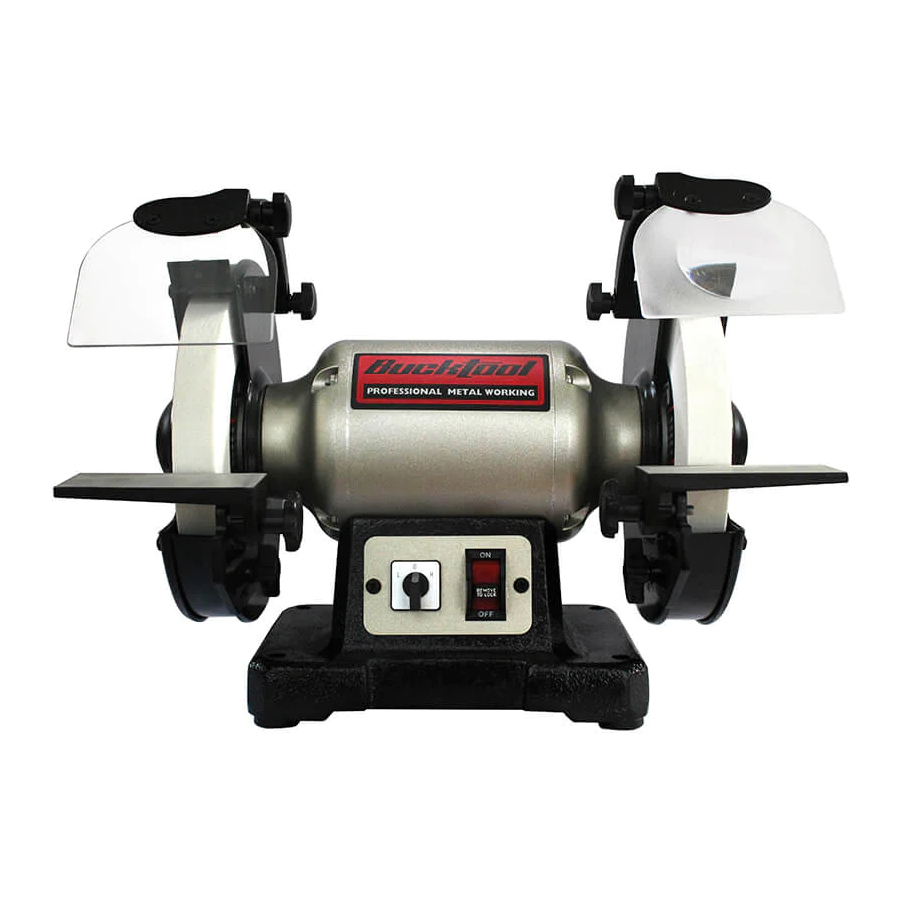
SPECIFICATIONS

For your own safety, read and follow all of the Safety Guidelines and Operating Instructions before operating this product.
| Motor | 120VAC, 60Hz, 1.8/3.1A |
| Speed | 1725RPM & 3450RPM |
| Shaft Diameter | 5/8" |
| Wheel Size | 8" x 1" x 5/8" |
| Wheel Grit | 80# / 120# |
| Wheel Material | White Aluminum Oxide |

To avoid electrical hazards, fire hazards or damage to the tool, use proper circuit protection. Use a separate electrical circuit for your tools. The grinder is wired at the factory for 120 Volt operation. It must be connected to a 120 V, 10 AMP branch circuit and use a 10 AMP time delay fuse or circuit breaker. To avoid shock or fire, replace power cord immediately if it is worn, cut or damaged in any way.
SAFETY GUIDELINES - DEFINITIONS
Your power tool and its Instruction Manual may contain "WARNING ICONS" (a picture symbol intended to alert you to and/or instruct you how to avoid a potentially hazardous condition). Understanding and heeding these symbols will help you operate your tool better and safer. Shown below are some of the symbols you may see.
 | SAFETY ALERT: Precautions that involve your safety. |
 | PROHIBITION |
 | WEAR EYE PROTECTION: Always wear safety goggles or safety glasses with side shields. |
 | WEAR RESPIRATORY AND HEARING PROTECTION: Always wear respiratory and hearing protection. |
 | READ AND UNDERSTAND INSTRUCTION MANUAL: To reduce the risk of injury, user and all bystanders must read and understand instruction manual before using this product. |
 | KEEP HANDS AWAY FROM THE MOVING PART AND CUTTING SURFACE: Failure to keep your hands away from the moving part and cutting surface will result in serious personal injury. |

Indicates an imminently hazardous situation which, if not avoided, will result in death or serious injury.

Indicates a potentially hazardous situation which, if not avoided, could result in death or serious injury.

Indicates a potentially hazardous situation which, if not avoided, may result in minor or moderate injury.
NOTICE: Used without the safety alert symbol indicates potentially hazardous situation which, if not avoided, may result in property damage.
Some dust created by power sanding, sawing, grinding, drilling and other construction activities contains chemicals known to the state of California to cause cancer, birth defects or other reproductive harm. Some examples of these chemicals are:
- Lead from lead-based paints;
- Crystalline silica from bricks and cement and other masonry products;
- Arsenic and chromium from chemically-treated lumber.
Your risk from these exposures varies, depending on how often you do this type of work. To reduce your exposure to these chemicals: work in a well ventilated area, and work with approved safety equipment, such as those dust masks that are specially designed to filter out microscopic particles. Avoid prolonged contact with dust from power sanding, sawing, grinding, drilling, and other construction activities. Wear protective clothing and wash exposed areas with soap and water. Allowing dust to get into your mouth, eyes, or lay on the skin may promote absorption of harmful chemicals.
Use of this tool can generate and/or disperse dust, which may cause serious and permanent respiratory or other injury. Always use NIOSH/OSHA approved respiratory protection appropriate for the dust exposure. Direct particles away from face and body.
POWER TOOL SAFETY
GENERAL SAFETY INSTRUCTIONS BEFORE USING THIS POWER TOOL
Safety is a combination of common sense, staying alert and knowing how to use your power tool.
- To avoid mistakes that could cause serious injury, do not plug the tool in until you have read and understood the following.
- Read all instructions before operating product. Failure to follow all instructions listed below may result in electric shock, fire and/or serious injury.
- READ and become familiar with the entire Instruction Manual. LEARN the tool's application, limitations and possible hazards.
![]()
- KEEP GUARDS IN PLACE and in working order.
- REMOVE ADJUSTING KEYS AND WRENCHES. Form the habit of checking to see that keys and adjusting wrenches are removed from the tool before turning ON.
- KEEP WORK AREA CLEAN. Cluttered areas and benches invite accidents.
- DO NOT USE IN DANGEROUS ENVIRONMENTS. Do not use power tools in damp locations, or expose them to rain or snow. Keep work area well lit.
- KEEP CHILDREN AWAY. All visitors and bystanders should be kept a safe distance from work area.
- MAKE WORKSHOP CHILD PROOF with padlocks, master switches or by removing starter keys.
- DO NOT FORCE THE TOOL. It will do the job better and safer at the rate for which it was designed.
- USE THE RIGHT TOOL. Do not force the tool or an attachment to do a job for which it was not designed.
- USE PROPER EXTENSION CORDS. Make sure your extension cord is in good condition. When using an extension cord, be sure to use one heavy enough to carry the current your product will draw. An undersized cord will result in a drop in line voltage and in loss of power which will cause the tool to overheat. The table shows the correct size to use depending on cord length and nameplate ampere rating. If in doubt, use the next heavier gauge. The smaller the gauge number, the heavier the cord.
- WEAR PROPER APPAREL. Do not wear loose clothing, gloves, neckties, rings, bracelets or other jewelry which may get caught in moving parts. Nonslip footwear is recommended. Wear protective hair covering to contain long hair.
- ALWAYS WEAR EYE PROTECTION. Any power tool can throw foreign objects into the eyes and could cause permanent eye damage. ALWAYS wear Safety Goggles (not glasses) that comply with ANSI Safety standard Z87.1. Everyday eyeglasses have only impact– resistant lenses. They ARE NOT safety glasses.
NOTE: Glasses or goggles not in compliance with ANSI Z87.1 could seriously injure you when they break.
![]()
- WEAR A FACE MASK OR DUST MASK. Sawing operation produces dust.
![]()
- SECURE WORK. Use clamps or a vise to hold work when practical. It is safer than using your hand and it frees both hands to operate the tool.
![]()
- DISCONNECT TOOLS FROM POWER SOURCE before servicing, and when changing accessories such as blades, bits and cutters.
- REDUCE THE RISK OF UNINTENTIONAL STARTING. Make sure switch is in the OFF position before plugging the tool in.
- USE RECOMMENDED ACCESSORIES. Consult this Instruction Manual for recommended accessories. The use of improper accessories may cause risk of injury to yourself or others.
- NEVER STAND ON THE TOOL. Serious injury could occur if the tool is tipped or if the cutting tool is unintentionally contacted.
- CHECK FOR DAMAGED PARTS. Before further use of the tool, a guard or other part that is damaged should be carefully checked to determine that it will operate properly and perform its intended function– check for alignment of moving parts, binding of moving parts, breakage of parts, mounting and any other conditions that may affect its operation. A guard or other part that is damaged should be properly repaired or replaced.
- NEVER LEAVE THE TOOL RUNNING UNATTENDED. TURN THE POWER "OFF". Do not walk away from a running tool until the blade comes to a complete stop and the tool is unplugged from the power source.
- DO NOT OVERREACH. Keep proper footing and balance at all times.
- MAINTAIN TOOLS WITH CARE. Keep tools sharp and clean for best and safest performance. Follow instructions for lubricating and changing accessories.
- DO NOT use power tool in presence of flammable liquids or gases.
- DO NOT operate the tool if you are under the influence of any drugs, alcohol or medicationn that could affect your ability to use the tool properly.
- Dust generated from certain materials can be hazardous to your health. Always operate saw in well-ventilated area and provide for proper dust removal.
![]()
People with electronic devices, such as pacemakers, should consult their physician(s) before using this product. Operation of electrical equipment in close proximity to a heart pacemaker could cause interference or failure of the pacemaker.- WEAR HEARING PROTECTION to reduce the risk of induced h earing loss.
![]()


BENCH GRINDER SAFETY
- Wear eye protection that complies with ANSI Z87.1 specifications.
![]()
- Use grinding wheels suitable for the speeds of the grinder.
- Stand beside the bench grinder during start-up, not facing directly in front.
- Do not remove the wheel guard.
- Do not use the grinding wheel to cut anything.
- Do not use anything to stress the grinding wheel.
- Use a grinding wheel dressing tool to shape or remove glaze from grinding wheels.
- Adjust distance between wheel and tool rest to maintain 1/8 inch (3.2 mm) or less separation as the diameter of the wheel decreases with use.
- Connect to a supply circuit protected by a circuit breaker or time-delay fuse.
- Secure the bench grinder to its supporting surface to prevent the grinder from tipping over, sliding, or walking on its supporting surface.
- Replace a cracked wheel immediately.
- Always use the guards and eye shields.
- Do not overtighten the wheel nut.
- Use only flanges furnished with this grinder.
- Always inspect grinding wheels prior to use for cracks, missing pieces, etc. Replace wheel immediately before use.
- USE ONLY GRINDING WHEELS that comply with ANSI B7.1 and rated greater than 3450 RPM.
- GUARD AGAINST ELECTRICAL SHOCK by preventing body contact with grounded surfaces. For example: pipes, radiators, ranges, refrigerator enclosures.
- DO NOT use wheels with incorrect size holes. NEVER use wheel washers or wheel screws that are defective or incorrect, and NEVER touch a grinding wheel or other moving parts.
- NEVER reach to pick up a workpiece, a piece of scrap, or anything else that is in or near the grinding path of the wheel.
- AVOID AWKWARD OPERATIONS AND HAND POSITIONS where a sudden slip could cause your hand to move into the wheel. ALWAYS make sure you have good balance.
- NEVER stand or have any part of your body in line with the path of the wheel.
- DO NOT USE TOOL IF SWITCH DOES NOT TURN IT ON AND OFF. Have defective switches replaced by an authorized service center.
- DO NOT TURN THE MOTOR SWITCH ON AND OFF RAPIDLY. This could cause the wheel to loosen and create a hazard. Should this ever occur, stand clear and allow the wheel to come to a complete stop. Disconnect your grinder from the power supply and retighten the wheel nut securely.
- RISK OF INJURY DUE TO ACCIDENTAL STARTING. Do not use in an area where children may be present.
- NEVER START THE GRINDER when the wheel is in contact with the workpiece.
- SECURE WORK. Always hold the workpiece firmly against the work rest.
- DO NOT USE THE BENCH GRINDER if the flange nut or clamp nut is missing or if the spindle shaft is bent.
- FREQUENTLY clean grinding dust from beneath the grinder.
- DO NOT OPERATE THIS TOOL WHILE UNDER THE INFLUENCE OF DRUGS, ALCOHOL OR ANY MEDICATION.
- ALWAYS STAY ALERT. Do not allow familiarity (gained from frequent use of your grinder) to cause a careless mistake. ALWAYS REMEMBER that a careless fraction of a second is sufficient to inflict severe injury.
- STAY ALERT AND EXERCISE CONTROL. Watch what you are doing and use common sense. Do not operate the tool when you are tired. Do not rush.
- SAVE THESE INSTRUCTIONS. Refer to them frequently and use them to instruct other users. If you loan someone this tool, loan them these instructions also.
- ALWAYS EASE THE WORKPIECE AGAINST THE ABRASIVE WHEELwhen starting to grind. A harsh impact can break the wheel. Use light pressure when starting to grind. Too much pressure on a cold wheel can cause the wheel to crack.
- USE ONLY FLANGES furnished with this bench grinder.
- IF ANY PART OF THIS GRINDER IS MISSING or should break, bend, fail in any way, or should any electrical component fail to perform properly, shut off the power switch, remove the machine plug from the power source and have damaged, missing, or failed parts replaced before resuming operation.
- SAFETY SHIELD AND SPARK DEFLECTOR. The safety shields and spark deflectors are adjustable for operator convenience. Operating the grinder without these features attached could result in serious injury. Do not grind with the safety shield raised. Always wear safety glasses for personal protection.
- WORK REST. The work rests are independently adjustable to compensate for wheel wear. Before grinding, make certain the work rests are adjusted properly. Generally, the object being ground is done slightly above the center of the grinding wheel.
- Lawn mower blades are usually sharpened on only one edge and dressed up slightly on the other. Perform this sharpening process on both cutting ends of the blade. After sharpening, balance the blade by removing additional material.
ELECTRICAL REQUIREMENTS AND SAFETY POWER SUPPLY AND MOTOR SPECIFICATIONS
To avoid electrical hazards, fire hazards, or damage to the tool, use proper circuit protection. Use a seperate electrical circuit for your tool. Your drill press is wired at the factory for 120 V operation. Connect to a 120 V, 10Amp circuit and use a 10 Amp time delay fuse or circuit breaker. To avoid shock or fire, if power cord is worn, cut, or damaged in any way, have it replaced immediately.
GROUNDING INSTRUCTIONS
This tool must be grounded while in use to protect the operator from electrical shock.
IN THE EVENT OF A MALFUNCTION OR BREAKDOWN, grounding provides a path of least resistance for electric currents and reduces the risk of electric shock. This tool is equipped with an electrical cord that has an equipment-grounding conductor and a grounding plug. The plug must be plugged into a matching receptacle that is properly installed and grounded in accordance with all local codes and ordinances.
DO NOT MODIFY THE PLUG PROVIDED. If it will not fit the receptacle, have the proper receptacle installed by a qualified electrician.
IMPROPER CONNECTION of the equipment grounding conductor can result in risk of electric shock. The conductor with the green insulation (with or without yellow stripes) is the equipment grounding conductor. If repair or replacement of the electrical cord or plug is necessary, do not connect the equipment grounding conductor to a live terminal.
CHECK with a qualified electrician or service person if you do not completely understand the grounding instructions, or if you are not certain the tool is properly grounded.
USE only 3-wire extension cords that have three-pronged grounding plugs with three-pole receptacles that accept the tool's plug. Repair or replace damaged or worn cords immediately.
Use a separate electrical circuit for your tool. This circuit must not be less than #18 wire and should be protected with a 10 Amp time lag fuse. Before connecting the motor to the power line, make sure the switch is in the off position and the electric current is rated the same as the current stamped on the motor nameplate. Running at a lower voltage will damage the motor.
GUIDELINES FOR EXTENSION CORDS USE THE PROPER EXTENSION CORD.
Make sure your extension cord is in good condition. Use an extension cord heavy the current your product will draw. An undersized cord will cause a drop in line voltage resulting in loss of power, overheating and burning out of the motor. The table below shows the correct size to use depending on cord length and nameplate ampere rating. If in doubt, use the next heavier gauge. The smaller the gauge number, the heavier the cord.
Make sure your extension cord is properly wired and in good condition. Always replace a damaged extension cord or have it repaired by a qualified technician before using it. Protect your extension cords from sharp objects, excessive heat and damp or wet areas.
| MINIMUM GAUGE FOR EXTENSION CORDS (AWG) | |||||
| (WHEN USING 120 VOLTS ONLY) | |||||
| Ampere Rating | Total Length of Cord | ||||
| More Than | Not More Than | 25 50100150 ft. | |||
| (7.62 15.2430.4845.72 m) | |||||
| AWG - American Wire Gauge | |||||
| 0 | 6 | 18 | 16 | 16 | 14 |
| 6 | 10 | 18 | 16 | 14 | 12 |
| 10 | 12 | 16 | 16 | 14 | 12 |
| 12 | 16 | 14 | 12 | Not Recommended | |
This tool is for indoor use only. Do not expose to rain or use in damp locations.
This tool is intended for use on a circuit that has a receptacle like the one illustrated in Fig. 1. Fig. 1 shows a three-pronged electrical plug and receptacle that has a grounding conductor. If a properly grounded receptacle is not available, an adapter (Fig.2) can be used to temporarily connect this plug to a two-contact grounded receptacle. The adapter (Fig. 2) has a rigid lug extending from it that MUST be connected to a permanent earth ground, such as a properly grounded receptacle box.
In all cases, make certain the receptacle is properly grounded. If you are not sure, have a qualified electrician check the receptacle.

Package contents
UNPACKING YOUR BENCH GRINDER

| No. | Description | Qty. |
| 1 | Bench grinder | 1 |
| 2 | Left / Right tool rest bracket | 1 each |
| 3 | Left / Right Tool rest | 1 each |
| 4 | Tool rest bracket knob / flat washer | 2 |
| 5 | Tool rest knob / flat washer | 2 |
| 6 | Left / Right eye shield assy | 1 each |
| 7 | Left / Right eye shield bracket | 1 each |
| 8 | Eye shield locking knob | 2 |
| 9 | Eye shield bracket knob / flat washer | 2 |
| 10 | Spark deflector | 2 |
| 11 | Philip screw assy | 2 |
| 12 | Buffing wheel | 1 |
| 13 | Spacer | 2 |
Key parts diagram

| No. | Description | Qty. |
| 1 | Eye shield | 2 |
| 2 | Spark deflector | 2 |
| 3 | White fine grinding wheel (60 Grit) | 1 |
| 4 | Tool rest | 2 |
| 5 | Tool rest bracket | 2 |
| 6 | Dual speed switch | 1 |
| 7 | Main switch | 1 |
| 8 | Tool rest bracket knob | 2 |
| 9 | Tool rest locking knob | 2 |
| 10 | Medium grinding wheel (120 Grit) | 1 |
| 11 | Eye shield locking knob | 2 |
| 12 | Eye shield bracket | 2 |
| 13 | Eye shield bracket knob | 2 |
Assembly instructions
ASSEMBLY AND ADJUSTMENTS
Estimated Assembly Time: 5 - 10 Minutes.
- To avoid injury, do not connect this bench grinder to the power source until it is completely assembled and adjusted, and you have read and understood this Instruction Manual.
- To reduce the risk of injury, turn unit off and disconnect it from power source before installing and removing accessories, before adjusting or when making repairs. An accidental start-up can cause injury.
INSTALLING TOOL RESTS (FIG. A,B)
- Attach the right tool rest bracket to the right wheel guard using a bracket knob and flat washer as shown in Fig. A.
NOTE: Ensure the locating pin passes through the bracket as shown and the registration disc of the bracket is facing inwards as shown.

- Attach the right tool rest to the bracket using a tool rest locking knob as shown in Fig. B. Ensure the flat profile of the tool rest is facing towards the stone.
NOTE: When in use, the tool rests should be adjusted to within 1/16 in. (1.6 mm) of the grinding wheel or other accessory being used.

- Attach the left tool rest following the same procedure as above.


INSTALLING SPARK DEFLECTOR (FIG. C)

- Use an M5x10 screw, washer and spring washer assy to attach the left spark deflector to the left wheel guard as shown in Fig. C. Secure the screw in place with a Phillips screwdriver.
- Attach the right spark deflector following the same procedure as above.
INSTALLING EYESHIELD ASSEMBLY (FIG. D,E)


- Attach the right eye shield bracket to the wheel guard using a flat washer, spring washer and eye shield bracket knob.
NOTE: The slotted part of the eye shield bracket must face towards the grinding wheel guard. - Fasten the right eye shield to the eye shield bracket using the eye shield locking knob.
- Attach the left eye shield assembly following the same procedure as above.
Operating instructions
GENERAL OPERATION
Keep all bystanders a safe distance away from the tool and not in direct line, front or back of the grinder.
- Your bench grinder has a white fine wheel (120 grit) for medium material removal and general purpose grinding, and a white medium wheel (60 grit) for fast material removal.
- To operate the bench grinder, always wear safety glasses and turn the tool on while standing at the side and not in front of the grinder. Allow it to reach full speed before grinding.
- Hold the workpiece firmly against the tool rest. Hold very small pieces with pliers or other suitable clamps.
- Feed the workpiece smoothly and evenly into the grinding wheel.
- Move the workpiece slowly and avoid jamming the workpiece against the wheel. If the wheel tends to slow down from excessive force, you should occasionally release the pressure to let the wheel return to full speed.
- The grinding wheels supplied with this unit are designed for different types of steel, wrought iron, and bronze.
- Never sharpen or grind anything made of aluminum, brass, copper, wood, plastic or any other non-metallic materials.
MOUNTING THE TOOL ON A WORKBENCH (FIG. F)
NOTE: FIRMLY BOLT THE GRINDER TO A WORK BENCH OR LEG STAND to gain maximum stability for your machine.

- Using the base of the bench grinder as a template, mark the bench through four holes in the casting.
- Bolt the bench grinder on the bench with bolts, washers and nuts.
NOTE: The mentioned fasteners are not supplied with the machine.
To reduce the risk of injury, turn off the grinder and disconnect it from power source before installing and removing accessories, adjusting and making repairs.
An accidental start-up can cause injury.
In order to conveniently carry the bench grinder from place to place, hold the left and right side of the wheel cover for transportation.
ON/OFF Switch (FIG. G)

- Press the power switch side marked "ON" and turn the daul speed switch at H or L position to turn the grinder on.
- Press the power switch side marked "OFF" to turn the grinder off.
- To lock the switch in the "OFF" position, grasp the end, of the switch key, and pull it out.
- With the power switch key removed, the switch will not operate.
- If the switch key is removed while the grinder is running, it can be turned off but cannot be restarted without inserting the switch key.
Always lock the switch off when the grinder is not in use. Remove the key and keep it in a safe place. In the event of a power failure, blown fuse, or tripped circuit breaker, turn the switch off and remove the key, preventing an accidental startup when the power comes on.
ADJUSTING THE SPEED OF THE GRINDER
Your grinder is equipped with a dual speed control switch.
- To high speed, turn the dual speed switch to the side marked "H".
- To low speed, turn the dual speed switch to the side marked "L".
NOTE:For your own safety, always turn the dual speed swtich at "O" position wait 3-5 seconds and then change to low speed, change speed keep this grinder is at low speed.
Grinding
- Adjust the tool rest to accommodate large or unusually shaped workpieces.
- Always keep the workpiece moving across the face of the grinding wheel. Grinding continuously on the same spot on the wheel will cause grooves to be worn into the wheel. The wheel may crack or become damaged more easily, and grinding of other objects will be difficult.
- If the workpiece becomes hot, dip it into water or oil to cool it.
- Always grind on the face of the wheel (around the diameter), NEVER on the sides. Side pressure on grinding wheels can cause cracking and damage.
- If the face of the grinding wheel is worn unevenly, becomes grooved, or is no longer smooth and flat, the wheel should be reshaped with a dressing tool (not supplied).
- If the grinding wheel is no longer round, the wheel should be reshaped with a dressing tool or replaced.
- If the surface of the wheel becomes loaded and dull with workpiece material, the wheel should be cleaned with a dressing tool.
- After reshaping, always readjust the tool rests and spark arrestors.
Grind only on the face of the grinding wheel and never the side of it.
Prolonged grinding will cause most materials to become hot. Use care when handling such materials.
SCISSORS
If possible, take the scissors apart to make the sharpening operation easier and safer.
Remove material only from the outside surface and work from the heavy end of the blade toward the tip.
KNIVES
Remove metal from both faces of most knives, working from the heavy end of the blade toward the tip.
SCREWDRIVERS
The end of a properly sharpened screwdriver will be a perfect rectangle, absolutely flat and perpendicular to the center line of the shank. The two sides and two faces will taper outward from the edge of the shoulder or shank. They should be flat with intersecting faces perpendicular. Hold each face of the screwdriver against the wheel to true it up, then ease the end straight into the stone to grind it true.
Maintenance
CHANGING GRINDING WHEELS (FIG. H, I, J, K, L)
Turn off and unplug the bench grinder.
Use only grinding wheels that measure 8 in. (200 mm) in diameter. This tool has 5/8 in. (15.88 mm) arbors on both sides.

- Raise the eye shield (1) out of the way and adjust the spark guard (2) in its highest setting.
- Loosen the knob and remove the tool rest assembly (3).
- Remove three screws (4) and lock nuts (5) from theside wheel cover and then remove the outer cover (6).
- To prevent wheel rotating, place a wood wedge (7) (not supplied) between the wheel and the wheel cover as shown in Fig. I.
NOTE: Using a metal object, like a screwdriver, is not recommended as it may damage the grinding wheel.

- Loosen the hex nut (8) by an adjustable wrench as shown in Fig. J.
NOTE: The nut on the left side of of the grinder has a standard left-hand thread (turn clockwise to loosen). The one on the right side has a right-hand thread (turn counterclockwise to loosen). Both wheel nuts tighten when turning toward the rear of the grinder and loosen when turning toward the front of the grinder.


- Remove the hex nut (8), the outside wheel flange (9) and the wheel (10) as shown in Flg. K.

- Inspect the wheel (10) for cracks, chips or any other visible damage (other than normal wear) and discard if such damage is found. Inspect the blotter/ cardboard disc for damage. If the blotter is missing or severely damaged, replace it with a piece of thin cardboard or blotter paper cut in the same shape. NEVER USE A GRINDING WHEEL WITHOUT A BLOTTER.

- Install the new wheel and make sure both wheel flanges (9) are in place with the concave sides toward wheels.
- To prevent wheel rotating, place a wood wedge (7) (not supplied) between the wheel and the wheel cover as shown in Fig. L.

- Tighten the hex nut (8) by an adjustable wrench.
NOTE: Do not overtighten the nut as this can crack the grinding wheel.

- Replace the wheel cover (6) and screws (4).
- Reinstall and adjust the tool rest to 1/16 in. (1.6 mm) away from the wheel and tighten securely.
- Adjust the eye shield (1) to a point between your eyes and the wheel.
BUFFING WHEEL OR WIRE WHEEL
A buffing wheel or wire (not included) wheel can be used with your grinder. You will need to add one or more spacers ( 1 ) to allow the arbour hex nut to tighten correctly. wire wheel: 8 x 5/8" with a maximum speed of 4500 RPM.

DRESSING A GRINDING WHEEL (FIG. N)
A Wheel Dresser (not included) is to be used to remove any forward wobble, buildup up of material on the grinding wheel, remove imperfections, and make the corners of the grinding wheel square.
NOTE: DO NOT use the Wheel Dresser on Wire Wheels (not included) if they are installed on the grinder.

- Adjust tool rest until it is in the flat horizontal position as shown and 1/16" away from the grinding wheel.
- Turn "ON" the Bench Grinder. Let the grinding wheel come up to a steady speed for one minute.
- After the grinding wheel has gotten to a steady speed, place the Wheel Dresser head flat on the Tool Rest.
- Firmly hold on to the handle of the Wheel Dresser.
- Move the Wheel Dresser forward until it makes light contact with the grinding wheel. After contact has been made, slide the Wheel Dresser side to side across the Tool Rest to dress the grinding wheel until the edges of the grinding wheel are square and the surface is clean.
- After the dressing the grinding wheel, turn "OFF" the Bench Grinder and let the grinding wheel come to a complete stop. Allow the grinding wheel to cool down for a period of 10 minutes before use.
- Inspect the grinding wheel for any irregularities that still need to be dressed, or for and damage. If there is damage to the wheel (cracks, major chips missing), replace the wheel immediately.
- The grinding wheel may now be slightly smaller in diameter after dressing. Re-adjust the tool rests and spark arrestors to maintain a 1/16" clearance to the grinding wheel.
GENERAL MAINTENANCE
For your own safety, turn switch "OFF" and remove plug from power source outlet before adjusting and maintaining your bench grinder. If power cord is worn, cut or damaged in any way, have it replacedb immediately.
- Regularly check the tool and use a soft brush to remove accumulated dust.
- Use only mild soap and damp cloth to clean the tool. Do not use alcohol, petrol or other similar cleaning agents.
- Do not make contact with the grinding wheels with any damp cloth.
- Never let any liquid get inside the tool; never immerse any part of the tool into a liquid.
- Wear safety goggles to protect your eyes while cleaning.
- Always make sure the eyeshields are transparent and not blocking the view of the grinding wheel.
- In normal use, grinding wheels may become cracked, grooved, rounded at the edges, chipped, out of true or loaded with foreign material. Cracked wheels should be replaced IMMEDIATELY. While any of the other conditions can be remedied with a dressing tool (included), new wheels sometimes require dressing to make them round.
- If you must replace a wheel be sure to obtain one with a safe rated speed at least as high as the "NO LOAD" RPM marked on your grinder's nameplate. Replacement wheels must have a 5/8 in. (15.88 mm) center hole, 8 in. (200 mm) diameter and should be a maximum of 1 in. (25 mm) wide. Test new wheels for cracks and maintain the existing sequence of retaining hardware. Be sure the tool is unplugged before attempting repairs.
- Never use caustic agents to clean the plastic parts of the tool.
- Water must never come into contact with the grinder.
- The use of any other accessories is not recommended and may result in serious injury.
Exploded view

Parts list
Package contents
| ID | Description | Size | Qty. |
| 1 | Philips screw+flat washer assy | M4×8 | 2 |
| 2 | Rubber foot | 4 | |
| 3 | Base plate | 1 | |
| 4 | Hex bolt + spring washer assy | M8×22 | 2 |
| 5 | Philips screw+spring washer+flat washer assy | M4×8 | 1 |
| 6 | Capacitor | 1 | |
| 7 | Base | 1 | |
| 8 | Switch | 1 | |
| 9 | Left tool rest bracket | 1 | |
| 10 | Left tool rest | 1 | |
| 11 | Philips screw | M5×8 | 4 |
| 12 | Reversing Switch | 1 | |
| 13 | Switch plate | 1 | |
| 14 | Cord baseplate | 1 | |
| 15 | Cord clip | 1 | |
| 16 | Power cord | 1 | |
| 17 | Philips screw+flat washer assy | M5×155 | 4 |
| 18 | End cup | 1 | |
| 19 | Wave spring washer | D47 | 1 |
| 20 | Bearing | 6204 | 2 |
| 21 | Stator | 1 | |
| 22 | Rotor | 1 | |
| 23 | Hex flange nut | M5 | 4 |
| 24 | Eye shield bracket knob | 2 | |
| 25 | Spring washer | D6 | 2 |
| 26 | Flat washer | D6 | 4 |
| 27 | Right eye shield bracket | 1 | |
| 28 | Right magnified eye shield | 1 | |
| 29 | Right inner guard | 1 | |
| 30 | Philips screw+spring washer assy | M5X10 | 6 |
| 31 | Philips screw+spring washer+flat washer assy | M5X8 | 2 |
| 32 | Spark deflector | 2 | |
| 33 | Right tool rest bracket | 1 | |
| 34 | Right tool rest | 1 | |
| 35 | Tool rest locking knob | 2 | |
| 36 | Flat washer | D8 | 2 |
| 37 | Tool rest bracket knob | 2 | |
| 38 | Wheel flange | 4 | |
| 39 | White grinding wheel | 120# | 1 |
| 40 | Hex nut | M12 | 1 |
| 41 | Right guard cover | 1 | |
| 42 | Philips screw | M5X48 | 6 |
| 43 | Left guard cover | 1 | |
| 44 | Hex nut | M12 left | 1 |
| 45 | Grinding wheel | 80# | 1 |
| 46 | Left inner guard | 1 | |
| 47 | Left eye shield | 1 | |
| 48 | Left eye shield bracket | 1 | |
| 49 | Eye shield locking knob | 2 | |
| 50 | Buffing wheel | 1 | |
| 51 | Spacer | 2 |
TROUBLESHOOTING GUIDE
To avoid injury from an accidental start, turn the switch OFF and always remove the plug from the power source before making any adjustments.
GENERAL
| SYMPTOM | PROBABLE CAUSE | CORRECTIVE ACTION |
Motor will not run | Not plugged into power outlet. | Plug it into the power outlet. |
| Power switch is not in ON position. | Turn the switch ON. Dual speed switch not at O position | |
| Motor cord cut or abraded. | Contact Professional Service Station for repair. | |
| Plug on cord is faulty. | Contact Professional Service Station for repair. | |
| Faulty motor. | Contact Professional Service Station for repair. | |
| Fuse on circuit breaks open. | Re-set; may be too many machines on line. | |
Grinding wheel vibrates or shakes | Grinding wheel is not fixed properly. | Adjust grinding wheel properly. See ADJUSTMENT section. |
| Other. | Contact Professional Service Station for repair. |
Having Problems?
Give us a chance to help you before returning this product
Email: service@bucktool.com
https://www.bucktool.com
![]() 909-255-1088 (8AM-5PM PST)
909-255-1088 (8AM-5PM PST)

https://www.bucktool.com
Documents / Resources
References
Download manual
Here you can download full pdf version of manual, it may contain additional safety instructions, warranty information, FCC rules, etc.
Download Bucktool TDS-200DS - 8 DUAL SPEED BENCH GRINDER Manual
Advertisement


Need help?
Do you have a question about the TDS-200DS and is the answer not in the manual?
Questions and answers