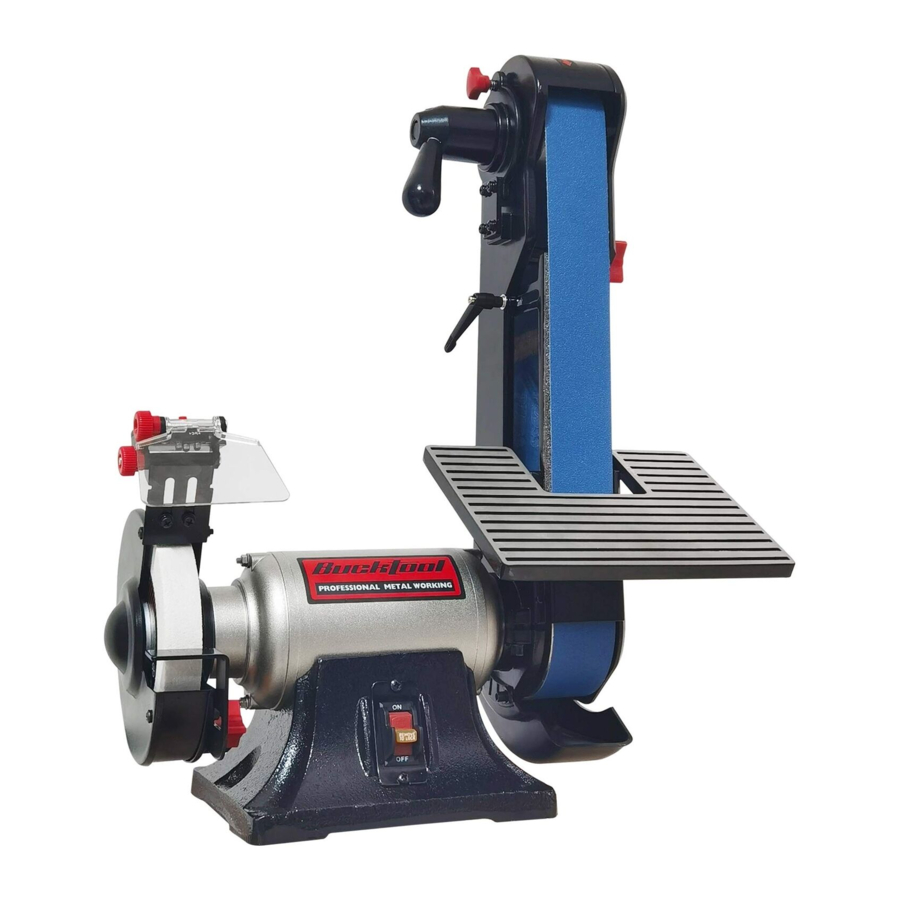
Bucktool BG2600 - 6" Bench Grinder & 2" x 42" Sander Combo Manual
- Instruction manual (24 pages)
Advertisement
- 1 SPECIFICATIONS
- 2 Safety guidelines
- 3 Package contents
- 4 Key parts diagram
- 5 Operating instructions
- 6 Maintenance
-
7
Troubleshooting
- 7.1 Grinder won't start
- 7.2 Excessive vibration
- 7.3 Motor overheating
- 7.4 Fuses are being blown or circuit breakers tripped
- 7.5 Machine slows when operating
- 7.6 Wavy condition on surface of workpiece
- 7.7 Lines on surface of workpiece
- 7.8 Burning spots or cracks in the workpiece
- 7.9 Wheel dulls quickly, grit falls off
- 7.10 Wheel clogs and workpiece shows burn marks
- 8 Exploded view
- 9 Parts list
- 10 Documents / Resources
SPECIFICATIONS

For your own safety, read and follow all of the Safety Guidelines and Operating Instructions before operating this product.
| Motor | 120VAC, 60Hz, 3.5A |
| Speed (no load) | 3450RPM |
| Belt size | 2" x 42" |
| Belt speed | 4480 FPM |
| Belt grit | 120 # |
| Wheel size | 6" x 1" x 1/2" |
| Wheel speed | 3450RPM |
| Wheel grit | 60 # |
Safety guidelines
GENERAL SAFETY GUIDELINES
- Operate in a safe work environment. Keep your work area clean, well lit and free of distractions.
- Keep anyone not wearing the appropriate safety equipment away from the work area.
- Store tools properly in a safe and dry location. Keep tools out of the reach of children.
- Do not install or use in the presence of flammable gases, dust or liquids.
- Always wear impact safety goggles that provide front and side protection for the eyes. Wear a full-face shield if your work creates metal filings or wood chips. (Eye protection equipment should comply with ANSI Z87.1 standards.)
- Wear gloves that provide protection based on the work materials or to reduce the effects of tool vibration.
- Non-skid footwear is recommended to maintain footing and balance in the work environment.
- Wear the appropriate rated dust mask or respirator.
- Do not operate any tool when tired or under the influence of drugs, alcohol or medications.
- Avoid wearing clothes or jewelry that can become entangled with the moving parts of a tool. Keep long hair covered or bound.
- Do not overreach when operating the tool. Proper footing and balance enables better control in unexpected situations.
- Securely hold the material using both hands. Applying the material to the grinder with only one hand can result in a loss of control.
- Never use a tool with a cracked or worn grinding wheel. Change the grinding wheel before using.
- Replace cracked wheel immediately. Use only flanges supplied with the grinder.
- Clean dust and debris from beneath the grinding wheels frequently.
- Do not start the tool if the grinding wheel is in contact with the workpiece.
- Always ensure the safety guards are attached correctly and do not operate the bench grinder without the guards attached. Adjust the distance between the wheel and the tool rest to maintain a 1/16 in. or less separation as the diameter of the wheel decreases with use.
- Use an appropriate dust respirator when working for an extended period of time. This will help prevent breathing in the fine dust created while grinding.
- Do not grind on the sides of grinding wheels unless they are specifically designed for that purpose.
- Before using the tool on the workpiece, run the tool at the highest speed, without a load, for at least 30 seconds in a safe position. Stop immediately if there is any vibration or wobbling that could indicate poor installation or a poorly balanced grinding wheel. Check the tool to determine the cause.
- Do not allow the motor to overload or overheat. Take breaks to rest the tool.
- Do not subject the grinding wheel to any lateral pressure as it may damage the tool or cause it to kickback.
ADDITIONAL SPECIFIC SAFETY RULES
- Only use a grinding wheel with the correct arbor size and shape that matches the grinder's spindle.
- Ensure the grinding wheel has a clean edge. Check the grinding wheel for wear or chipping and replace if necessary.
- Never install more than one grinding wheel at a time unless the tool and wheels are designed for that purpose.
- A large amount of sparks will be created when working with a grinding wheel. Hold the tool so that sparks fly away from you and other persons or flammable materials. Have a fully charged fire extinguisher present.in the event of a fire.
- Do not subject the grinding wheel to any lateral pressure as it may damage the tool or cause it to kickback.
- Disconnect tool from power source before cleaning, servicing, changing parts/accessories or when not in use.
- Protect yourself against electric shocks when working on electrical equipment. Avoid body contact with grounded surfaces. There is an increased chance of electrical shock if your body is grounded.
- Do not expose tool to rain or wet conditions. Water entering a power tool will increase the risk of electric shock.
- Do not disconnect the power cord in place of using the ON/OFF switch on the tool. This will prevent an accidental startup when the power cord is plugged into the power supply.
- Do not alter any parts of the tool or accessories. All parts and accessories are designed with built-in safety features that may be compromised if altered.
- Make certain the power source conforms to requirements of your equipment.
- Do not allow the tool to run without load for an extended period of time, as this will shorten its life.
- Do not cover the air vents. Proper cooling of the motor is necessary to ensure normal life of the tool.
- Avoid unintentional starting. Ensure the switch is off when connecting to the power source.
- In the event of a power failure, turn off the machine as soon as the power is interrupted. The possibility of accidental injury could occur if the power returns and the unit is not switched off.
- Disconnect the power source before installing or servicing the tool.
- After making adjustments, make sure that any adjustment devices are securely tightened.
- Remove adjusting keys and wrenches before turning the tool on. A wrench or a key that is left attached to a rotating part of the tool increases the risk of personal injury.
- Never force the tool. Excessive pressure could break the tool, resulting in damage to your workpiece or serious personal injury. If your tool runs smoothly under no load, but does not run smoothly under load, then excessive pressure is being used.
- Do not touch an operating motor. Motors can operate at high temperatures.
- Only use accessories that are specifically designed for use with the tool. Ensure the accessory is tightly installed.
- Only use an accessory that exceeds the No Load Speed rating.
- Do not touch an operating motor. Motors can operate at high temperatures and can cause a burn injury.
- Insert the power cord plug directly to the power supply whenever possible. Use extension cords or surge protectors only when the tool's power cord cannot reach a power supply from the work area.
- Do not operate this tool if the power cord is frayed or damaged as an electric shock may occur, resulting in personal injury or property damage.
- Inspect the tool's power cord for cracks, fraying or other faults in the insulation or plug before each use.
- Discontinue use if a power cord feels more than comfortably warm while operating the tool.
- Keep all connections dry and off the ground to reduce the risk of electric shock. Do not touch plug with wet hands.
- Do not allow people, mobile equipment or vehicles to pass over unprotected power cords.
- This tool vibrates during use. Repeated or long-term exposure to vibration may cause temporary or permanent physical injury, particularly to the hands, arms and shoulders.

Read, understand and observe all instructions in this manual before using or operating the tool for which it is written and supplied. Ensure that anyone who is to use the tool has read and understood the instructions provided.
Electrical
A separate electrical circuit should be used for your machines. This circuit should not be less than #12 wire and should be protected with a 20-A time-lag fuse. If an extension cord is used, use only 3-wire extension cords which have 3-pronged grounding type plugs and matching receptacle which will accept the machine's plug. Before connecting the machine to the power line, make sure the switch is in the "OFF" position and be sure that the electric current is of the same characteristics as indicated on the machine. All line connections should make good contact. Running on low voltage will damage the machine.

MOTOR SPECIFICATIONS
Your machine is wired for 120 V, 60Hz alternating current. Before connecting the machine to the power source, make sure the switch is in the "OFF" position.
GROUNDING INSTRUCTIONS
All grounded, cord-connected machines: In the event of a malfunction or breakdown, grounding provides a path of least resistance for electric current to reduce the risk of electric shock. This machine is equipped with an electric cord having an equipment grounding conductor and a grounding plug.

DO NOT EXPOSE THE MACHINE TO RAIN OR OPERATE THE MACHINE IN DAMP LOCATIONS.
THIS MACHINE MUST BE GROUNDED WHILE IN USE TO PROTECT THE OPERATOR FROM ELECTRIC SHOCK. !
The plug must be plugged into a matching outlet that is properly installed and grounded in accordance with all local codes and ordinances.
Do not modify the plug provided–if it will not fit the outlet, have the proper outlet installed by a qualified electrician.
Improper connection of the equipment-grounding conductor can result in risk of electric shock. The conductor with insulation having an outer surface that is green with or without yellow stripes is the equipment-grounding conductor. If repair or replacement of the electric cord or plug is necessary, do not connect the equipment-grounding conductor to a live terminal.
Check with a qualified electrician or service personnel if the grounding instructions are not completely understood, or if in doubt as to whether the machine is properly grounded.
Use only 3-wire extension cords that have 3-pronged grounding type plugs and matching 3-conductor receptacles that accept the machine's plug, as shown in Fig. A. Repair or replace damaged or worn cord immediately.
MINIMUM GAUGE FOR CORD SETS
Use proper extension cords. Make sure your extension cord is in good condition and is a 3-wire extension cord which has a 3-pronged grounding type plug and matching receptacle which will accept the machine's plug. When using an extension cord, be sure to use one heavy enough to carry the current of the machine. An undersized cord will cause a drop in line voltage, resulting in loss of power and overheating. The table shows the correct gauge to use depending on the cord length. If in doubt, use the next heavier gauge. The smaller the gauge number, the heavier the cord.

In all cases, make certain the receptacle in question is properly grounded.
If you are not sure, have a electrician check the receptacle.
Package contents

| No. | Description | Qty. | No. | Description | Qty. |
| 1 | Bench grinder sander | 1 | 10 | Inner hex bolt assy M5x10 | 2 |
| 2 | Sanding belt 2"x42" | 3 | 11 | Inner hex bolt M10x16 | 1 |
| 3 | Tool rest for grinding | 1 | 12 | Flat washer D10 | 1 |
| 4 | Tool rest locking knob | 1 | 13 | Work table support | 1 |
| 5 | Eye shield | 1 | 14 | Knife sanding work table | 1 |
| 6 | LED light | 1 | 15 | Flat washer D8 | 1 |
| 7 | Flat washer D8 | 1 | 16 | Table lock lever | 1 |
| 8 | Philips screw assy M5x10 | 2 | 17 | Wood sanding work table | 1 |
| 9 | Dust port | 1 | |||
Key parts diagram

Operating instructions
Estimated Assembly Time: 5 - 10 Minutes.
INSTALLING WORK REST ON GRINDING WHEEL

- Attach the left tool rest (1) to the grinder as the upper slot (2) to the nut (3) and lower slot (4) to the protrude cylinder (5).
- Place the lock knob (6) through the washer (7) and lower slot (5) into the hold (8) to lock the tool rest (1) in place.
NOTE:When in use, the tool rests should be adjusted to within 1/8 in. (3.2 mm) of the grinding wheel or other accessory being used.
INSTALLING THE LED LIGHT AND EYE SHIELD ASSEMBLY

- Tighten the LED light assembly (1) to grinder with two composite screws (2) using a Philips screwdriver.
- Attach eye shield (3) to the support bracket (4) of the LED light assembly.
- Tighten the eye shield (3) by using a carriage bolt (5) and lock knob (6) as shown.
NOTE: Adjust eye shield to appropriate distance from tool rest avoiding interference when operation.
INSTALLING KNIFE SANDING WORK TABLE

- Mount the work table support (1) to left side of belt housing (2) using flat washer (3) and hex cap screw (4).
- Belt work talbe knob (5) and flat washer (6) through hole in the work table (7).
- Thread knob into the work table support (1). Tighten finger tight.
- Position work table so that distance between work table and belt is 1/16˝ or less. Use square to set work table 90º to belt. Secure all nuts and bolts tight.
INSTALLING WOOD SANDING WORK TABLE

- Mount work table (1) to left side of belt housing (2) using hex cap screw (3) and flat washer (4).
- Set the work table at right angle to the belt
- Be sure gap between table and belt is 1/16˝ or less. Tighten hex cap screw (3) to secure table position.
INSTALLING BELT DUST PORT

Attach the belt dust port (1) to the sanding belt with the philips screws (2). The opening of the dust port is 1-7/32 inch in diameter and can be connected to a utility vacuum or a dust collector.
MOUNTING BELT / DISC SANDER TO WORKBENCH
- Place the sander on a surface that is level but also provides enough room on all sides for the workpiece and for the operator (or bystanders) to not be standing in line with the wood while using the tool. Allow room for the belt to be positioned horizontally or vertically.
- The hardware to mount this sander is NOT supplied with the sander.
TO PROPERLY TRACK THE SANDING BELT

- Plug in the sander.
- Turn power switch ON, then immediately OFF, noting whether the belt (1) tends to slide off its track, and to which side (front or back) of the sander.
- If the sanding belt does not slide to either side, it is tracking properly.
- Viewed from the switch end, if the sanding belt runs toward the grinding wheel side, slightly turn the belt tracking knob (2) counterclockwise (up).
- Viewed from the switch end, if the sanding belt runs away from the grinding wheel side, slightly turn the tracking knob (2) clockwise (down).
- Turn power switch ON, then immediately OFF again, again taking note of any belt movement.
- Readjust tracking knob (2) another 1/4 turn, necessary.
LEVELING THE SANDING BELT
The support rod is designed for adjusting the level of sanding belt. To adjust, please do the following.

- Loosen the lock nut (1) on the upper end of the support rod (2) with the adjustable wrench.
- Adjust the support rod (2) upward or downward to leveling the sanding belt (3).
- When the level of the sanding belt (3) is achieved, tighten the lock nut (1).
ON/OFF SWITCH
The ON/OFF power switch is located on the front of the sander, and incorporates a removable safety key.
In situations where the sander may be left unattended, the operator has the option of removing the "black" safety key of the ON/OFF switch to render the sander inoperable. When the operator is ready to use the machine again, simply insert the "black" safety key into the slot in the switch and pushing it in until it "seats."
BELT VERTICAL SANDING
Your bench grinder sander - belt station can sand vertically as well as horizontally. Depending on operator needs and the workpiece, the work table can be used with either the horizontal or vertical position.
To change from one position to the other:
- Loosen the inner hex screw (1) by turning it counterclockwise with the 8 mm hex key.
- Manually move the work support station into the vertical or horizontal position, as required.
- Retighten the inner hex screw (1) by turning it clockwise.
CONTOUR SANDING
- Belt platen (1) can be removed for contour sanding. Loosen locking knob (2) holding platen to belt housing (3). Control the belt platen down or remove to use.
- Replace belt cover and belt cover knobs. When contour sanding is complete, replace belt platen. Position belt platen as close to belt as possible so that platen does not contact belt.
NOTE: The maximum down distance of the belt platen is 2.5cm.
CLEANING
- Keep machine and workshop clean. Do not allow sawdust to accumulate on the belt.
- Keep the wheels clean. Dirt on wheels will cause poor tracking and belt slippage.
- Operate sander with dust collector to keep dust from accumulating.
- Be certain motor is kept clean and is frequently vacuumed free of dust.
- Use soap and water to clean painted parts, rubber parts and plastic guards.
NOTE: After sanding wood or non-metallic material, always clean dust collector and guards of sawdust before grinding metal. Sparks could ignite debris and cause a fire.
Maintenance
REPLACING GRINDING WHEEL

Turn off and unplug the bench grinder.
Use only grinding wheel that measure 6 in. (150 mm) in diameter. This tool has 1/2 in. (12.7 mm) arbors on both sides.


- Raise the eye shield (1) out of the way and adjust the spark deflector (2) in its highest setting.
- Loosen the knob (3) and remove the tool rest assembly (4).
- Remove three screws (5) and lock nuts (6) from the left side wheel cover and then remove the outer cover (7).
- To prevent wheel rotating, place a wood wedge (8) (not supplied) between the wheel and the wheel cover. NOTE: Using a metal object, like a screwdriver, is not recommended as it may damage the grinding wheel.
- Loosen the hex nut (9) by an adjustable wrench as shown in Fig. F.
NOTE: The nut on the left side of the grinder has a standard left-hand thread (turn clockwise to loosen). The wheel nut tighten when turning toward the rear of the grinder and loosen when turning toward the front of the grinder.
- Remove the hex nut (9), the outside wheel flange (10) and the wheel (11).
- Inspect the wheel (11) for cracks, chips or any other visible damage (other than normal wear) and discard if such damage is found. Inspect the blotter/cardboard disc for damage. If the blotter is missing or severely damaged, replace it with a piece of thin cardboard or blotter paper cut in the same shape. NEVER USE A GRINDING WHEEL WITHOUT A BLOTTER.
- Install the new wheel and make sure both wheel flanges (10) are in place with the concave sides toward wheels.
- To prevent wheel rotating, place a wood wedge (12) (not supplied) between the wheel and the wheel cover.
- Tighten the hex nut (9) by an adjustable wrench.
NOTE: Do not overtighten the nut as this can crack the grinding wheel. - Replace the wheel cover (7) and screws (5).
- Reinstall and adjust the tool rest to 1/16 in. (1.6 mm) away from the wheel and tighten securely.
- Adjust the eye shield (1) to a point between your eyes and the wheel.
REPLACING WIRE WHEEL (NOT INCLUDED)
A wire wheel (not included) can be used with your grinder. You will need to add one or more spacers (1) (not included) to allow the arbour hex nut to tighten correctly.

REPLACING SANDING BELT
Sanding belt should be replaced when worn, torn, or glazed.

- Position the belt housing horizontally as shown. Loosen the inner hex screw (1) by using a 8 mm hex wrench, turning it counte rclockwise.
- Loosen the belt cover lock knobs (2) to remove the belt cover(3).
- Remove the philips screw (4) by using a phillips screwdriver and then remove the belt cover support (5).
- Release belt tension by pulling down on tension handle (6). Slide old belt off the drive and tracking wheels.
- Pull down on the tension handle (6) and slide new belt over the drive and tracking wheels, center belt on wheels.
- Replace the belt cover support (5) and tighten screw (4).
- Replace belt cover (3) and knobs (2).
- Push the belt by hand and check if the sanding belt tends running to one side or the other of the two drums.
- View from the switch end of sander, if the sanding belt runs toward the grinding wheel size, slightly turn the tracking knob (7) counterclockwise (up).
- View from the switch end of sander, if the sanding belt runs away from the grinding wheel side, slightly turn the tracking knob (7) clockwise (down).
- Plug in the sander and turn the switch ON and OFF quickly to check if the sanding belt moves to either side. Re-adjust and fine-tune the belt tracking if necessary.
NOTE: The tension of belt can be adjust by choosing different spring locking position. Pls choose hole a or b for thicker and harder belts; choose hole c or d for thin and soft belts.
Troubleshooting
To avoid injury from an accidental start, turn the switch OFF and always remove the plug from the power source before making any adjustments.
| Problem(s) | Possible Cause(s) | Suggested Solution(s) |
Grinder won't start |
|
|
Excessive vibration |
|
|
Motor overheating |
|
|
Fuses are being blown or circuit breakers tripped |
|
|
Machine slows when operating |
|
|
Wavy condition on surface of workpiece |
|
|
Lines on surface of workpiece |
|
|
Burning spots or cracks in the workpiece |
|
|
Wheel dulls quickly, grit falls off |
|
|
Wheel clogs and workpiece shows burn marks |
|
|
Exploded view

Parts list
| Item | DESC. | SPEC. | QTY |
| 1 | Philips Screws | M5X45 | 3 |
| 2 | Left Guard Cover | 1 | |
| 3 | Hex Nut | M12 left | 1 |
| 4 | Flange | 2 | |
| 5 | White Grinding Wheel | 60# | 1 |
| 6 | Philips Screws + Spring Washer Assy | M5X10 | 6 |
| 7 | Left Inner Guard | 1 | |
| 8 | Hex Flange Nut | M5 | 3 |
| 9 | Left Tool Rest | 1 | |
| 10 | Flat Washer | D8 | 2 |
| 11 | Tool Rest Locking Knob | M8X9 | 1 |
| 12 | Spark Deflector | 1 | |
| 13 | Bushing | 1 | |
| 14 | Eye Shield Locking Knob | 1 | |
| 15 | Battery | 2 | |
| 16 | Led Light | 1 | |
| 17 | Hex Flange Nut | M5 | 2 |
| 18 | Left End Cap | 1 | |
| 19 | Wave Spring Washer | D35 | 1 |
| 20 | Bearing | 6003 | 2 |
| 21 | Cord & Pulg | 1 | |
| 22 | Cord Plate | 1 | |
| 23 | Philips Screw | M5X8 | 4 |
| 24 | Cord Clip | 6P4 | 1 |
| 25 | Rotor | 1 | |
| 26 | Stator | 1 | |
| 27 | Right End Cap | 1 | |
| 28 | Philips Screw + Flat Washer Assy | M5X190 | 4 |
| 29 | Toothed Lock Washer | D4 | 1 |
| 29-1 | Philips Screw Assy | M4X8 | 1 |
| 30 | Cord Bushing | 1 | |
| 31 | Switch | HY7 | 1 |
| 32 | Philips Screw | M4X8 | 1 |
| 33 | Switch Plate | 1 | |
| 34 | Base | 1 | |
| 35 | Capacitor | 1 | |
| 36 | Philips Screw + Spring Washer Assy | M6X20 | 2 |
| 37 | Base Plate | 1 | |
| 38 | Rubber Foot | 4 | |
| 39 | Philips Screw + Flat Washer Assy | M4X12 | 4 |
| 40 | Belt Tension Handle | 1 | |
| 41 | Inner Hex Bolt | M8X10 | 1 |
| 42 | Tension Handle Base | 1 | |
| 43 | Tension Spring | 1 | |
| 44 | Belt Tracking Knob | M6 | 1 |
| 45 | Belt Adjustable Spring | 1 | |
| 46 | Support Base | 1 | |
| 47 | Eccentric Shaft Assy | 1 | |
| 48 | Shaft Circlip | D16 | 1 |
| 49 | Ball Bearing | 6202 | 2 |
| 50 | Internal Circlip | D35 | 2 |
| 51 | Idler Wheel | 1 | |
| 52 | Shaft Circlip | D15 | 1 |
| 53 | Sanding Belt | 1 | |
| 54 | Shaft Circlip | D6 | 2 |
| 55 | Belt Cover | 1 | |
| 56 | Belt Cover Lock Knob | M8 | 2 |
| 57 | Philips Screw Assy | M5X10 | 6 |
| 58 | Belt Adjustment Plate | 65Mn | 2 |
| 59 | Foot Support | 1 | |
| 60 | Hex Bolt | M8X90 | 1 |
| 61 | Hex Nut | M8 | 1 |
| 62 | Belt Cover Support | 1 | |
| 63 | Bolt | M6X18 | 2 |
| 64 | Belt Platen | 1 | |
| 65 | Inner Hex Bolt | M10X16 | 1 |
| 66 | Big Flat Washer | D10 | 1 |
| 67 | Locking Knob | M6 | 2 |
| 68 | Inner Hex Bolt | M8X25 | 1 |
| 69 | Belt Housing | 1 | |
| 70 | Belt Limited Plate | 1 | |
| 71 | Driving Wheel | 1 | |
| 72 | Hex Nut | M12 | 1 |
| 73 | Work Table Support | 1 | |
| 74 | Inner Hex Wrench | S=4 | 1 |
| 75 | Inner Hex Wrench | S=6 | 1 |
| 76 | Inner Hex Wrench | S=8 | 1 |
| 77 | Table Locking lever | M8X28 | 1 |
| 80 | Bolt | M5X60 | 1 |
| 81 | Bolt | M5X55 | 1 |
| 82 | Eye Shield | 1 | |
| 83 | Dust Port | 1 | |
| 84 | Inner Hex Bolt Assy | M5X10 | 2 |
| 85 | Knife Sanding Work Table | 1 | |
| 86 | Wood Sanding Work Table | 1 |
Having Problems?
Give us a chance to help you before returning this product
Email: service@bucktool.com https://www.bucktool.com
![]() 909-255-1088 (8AM-5PM PST)
909-255-1088 (8AM-5PM PST)

https://www.bucktool.com
Documents / Resources
References
Download manual
Here you can download full pdf version of manual, it may contain additional safety instructions, warranty information, FCC rules, etc.
Download Bucktool BG2600 - 6" Bench Grinder & 2" x 42" Sander Combo Manual
Advertisement


Need help?
Do you have a question about the BG2600 and is the answer not in the manual?
Questions and answers