Table of Contents
Advertisement
Quick Links
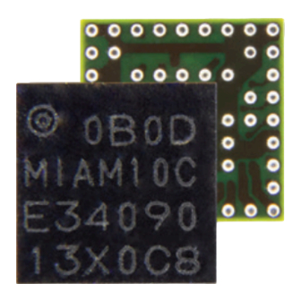
MIA-M10C
Standard precision GNSS module
Professional grade
Integration manual
Abstract
This document describes the features and application of the u-blox MIA-
M10C module. MIA-M10C is an ultra-small form factor and ultra-low-power
GNSS receiver compatible with external active antennas for asset tracking
applications.
www.u-blox.com
UBX-23001616 - R03
C1-Public
Advertisement
Table of Contents

Related Manuals for Ublox MIA-M10C


Summary of Contents for Ublox MIA-M10C
- Page 1 Professional grade Integration manual Abstract This document describes the features and application of the u-blox MIA- M10C module. MIA-M10C is an ultra-small form factor and ultra-low-power GNSS receiver compatible with external active antennas for asset tracking applications. www.u-blox.com UBX-23001616 - R03...
- Page 2 MIA-M10C - Integration manual Document information Title MIA-M10C Subtitle Standard precision GNSS module Document type Integration manual Document number UBX-23001616 Revision and date 19-Jan-2024 Disclosure restriction C1-Public This document applies to the following products: Product name Type number FW version IN/PCN reference RN reference...
-
Page 3: Table Of Contents
MIA-M10C - Integration manual Contents 1 System description.......................6 1.1 Overview..............................6 1.2 Architecture..............................6 1.2.1 Block diagram..........................6 1.3 Pin assignment............................6 2 Receiver configuration.......................10 2.1 Basic receiver configuration....................... 11 2.1.1 Basic hardware configuration....................11 2.1.2 Internal LNA mode configuration..................... 11 2.1.3 GNSS signal configuration......................11 2.1.4 Communication interface configuration................. - Page 4 MIA-M10C - Integration manual 3.7.2 GNSS time bases......................... 45 3.7.3 Navigation epochs........................46 3.7.4 iTow timestamps..........................47 3.7.5 Time validity..........................47 3.7.6 UTC representation........................48 3.7.7 Leap seconds..........................48 3.7.8 Date ambiguity..........................49 3.8 Time mark.............................. 50 3.9 Time pulse.............................. 51 3.9.1 Recommendations........................52 3.9.2 Time pulse configuration......................53...
- Page 5 MIA-M10C - Integration manual 5.1 Safety..............................78 5.1.1 ESD precautions...........................78 5.1.2 Safety precautions........................79 5.2 Packaging............................... 79 5.2.1 Reels..............................79 5.2.2 Tapes...............................79 5.2.3 Moisture sensitivity level......................80 5.3 Soldering..............................81 Appendix............................ 83 A Migration..............................83 A.1 Software changes........................... 83 B Reference designs............................84 B.1 Typical design..........................84 B.2 Antenna supervisor designs......................
-
Page 6: System Description
MIA-M10C is cost and power optimized for designs where a SAW filter and an LNA are integrated in the external active antenna. It operates with an outstanding low power consumption of less than 15 mW in a 1 Hz cyclic tracking power save mode. - Page 7 MIA-M10C - Integration manual Figure 2: MIA-M10C pin assignment Pin no. Name PIO no. I/O Description Remarks Connect to GND Connect to GND Connect to GND Leave open if not used. See Real-time clock for more RTC_I RTC input information. RTC_O RTC output...
- Page 8 MIA-M10C - Integration manual Pin no. Name PIO no. I/O Description Remarks The RF signal line is DC blocked internally. The line must match the 50 Ω impedance. RF_IN GNSS signal input See sections RF front-end Layout for more information about the RF signal considerations.
- Page 9 Connect to GND for 1.8 V supply, or leave open for 3.3 VIO_SEL V_IO supply V supply Reserved Leave open Connect to GND Connect to GND Table 1: MIA-M10C pin assignment UBX-23001616 - R03 1 System description Page 9 of 93 C1-Public...
-
Page 10: Receiver Configuration
MIA-M10C. MIA-M10C is configured using UBX configuration interface keys. The configuration database in the receiver's RAM holds the current configuration, which is used by the receiver at runtime. It is constructed at the receiver startup from several sources of configuration. -
Page 11: Basic Receiver Configuration
10 receivers support three modes for the internal low-noise amplifier (LNA): normal gain, low gain, and bypass mode. The MIA-M10C default is the normal mode. With a high-gain external active antenna, the low gain or the bypass mode can be used to save power. -
Page 12: Communication Interface Configuration
MIA-M10C - Integration manual which are functional only with GPS. In addition to the configuration key for each constellation, there is a configuration key for each signal supported by the firmware. For example, if CFG-SIGNAL-GPS_ENA is set to zero, all signals from the GPS constellation are disabled. -
Page 13: Message Output Configuration
MIA-M10C - Integration manual Interface Configuration groups CFG-I2C-*, CFG-I2CINPROT-*, CFG-I2COUTPROT-*, CFG-TXREADY-* Table 4: Interface configuration 2.1.5 Message output configuration The receiver supports two protocols for output messages: industry-standard NMEA and u-blox UBX. Any message type can be enabled or disabled individually and the output rate is configurable. -
Page 14: High Performance Navigation Update Rate Configuration
MIA-M10C - Integration manual Using some antenna supervisor features may require disabling the UART or I2C interface and reconfiguring the PIOs as antenna supervisor pins. Table 5 describes the configuration items. Configuration item Description Comments CFG-HW-ANT_CFG_VOLTCTRL Enable active antenna voltage control CFG-HW-ANT_CFG_SHORTDET... - Page 15 MIA-M10C - Integration manual maximum achievable navigation update rate. In regions with a lower number of available BeiDou satellites, a higher navigation rate is achieved. The maximum navigation update rate given in the datasheet is provided for a minimum of 98% position fix rate, i.e., up to 2% position fixes can get lost in case of high availability of signals.
-
Page 16: Navigation Configuration
MIA-M10C - Integration manual 2.2 Navigation configuration This section presents various configuration options related to the navigation engine. These options can be configured through CFG-NAVSPG-* configuration keys. 2.2.1 Dynamic platform The dynamic platform model can be configured through the CFG-NAVSPG-DYNMODEL configuration item. For the supported dynamic platform models and their details, see... -
Page 17: Navigation Output Filters
MIA-M10C - Integration manual Configuration item Description CFG-NAVSPG-FIXMODE By default, the receiver calculates a 3D position fix if possible but it reverts to 2D position if necessary (auto 2D/3D). The receiver can be configured to only calculate 2D (2D only) or 3D (3D only) positions. -
Page 18: Static Hold
MIA-M10C - Integration manual message ( heading field), NMEA-RMC message ( cog field), and NMEA-VTG message ( cogt field). The filtering level can be set via the CFG-ODO-COGLPGAIN configuration item and must be between 0 (heavy low-pass filtering) and 255 (weak low-pass filtering). -
Page 19: Freezing The Course Over Ground
MIA-M10C - Integration manual Figure 4: Flowchart of static hold mode 2.2.6 Freezing the course over ground If the low-speed course over ground filter is deactivated or inactive (see section Low-speed course over ground filter), the receiver derives the course over ground from the GNSS velocity information. -
Page 20: Super-Signal (Super-S) Technology
2.3 OTP memory configuration MIA-M10C contains a one-time programmable (OTP) memory. This is a non-volatile memory for storing configuration settings and ROM patches permanently in the device. The stored data cannot be modified after it has been initially programmed. The device applies the settings and ROM patches on the device startup. -
Page 21: Receiver Functionality
For receiving correction data, MIA-M10C automatically chooses the best SBAS satellite as its primary source. It selects only one satellite since the information received from other SBAS satellites is redundant and could be inconsistent. -
Page 22: Qzss Slas
Multiple QZSS SLAS signals can be received simultaneously. When receiving QZSS SLAS correction data, MIA-M10C will autonomously select the best QZSS satellite. The selection strategy is determined by the quality of the QZSS L1S signals, the receiver configuration (test mode allowed or not), and the location of the receiver with respect to the QZSS SLAS coverage area. -
Page 23: Communication Interfaces And Pios
CPU. Each protocol can be enabled on several interfaces at the same time with individual settings for, for example, baud rate, message rates, and so on. In MIA-M10C, several protocols can be enabled on a single interface at the same time. -
Page 24: I2C
MIA-M10C - Integration manual Baud rate Data bits Parity Stop bits 230400 none 460800 none 921600 none Table 15: Possible UART interface configurations Allow a short time delay of typically 100 ms between sending a baud rate change message and providing input data at the new rate. Otherwise some input characters may be ignored or the port could be disabled until the interface is able to process the new baud rate. - Page 25 MIA-M10C - Integration manual Figure 6: I2C register layout 3.2.2.2 Read access types The host can choose one of the following two modes: • Random read access: the controller first reads the number of available bytes at the 0xFD and 0xFE before accessing the data at 0xFF.
- Page 26 MIA-M10C - Integration manual Figure 7: I2C random read access If "current address" is used, an address pointer in the receiver is used to determine which register to read. This address pointer will increment after each read operation unless it is already pointing at register 0xFF, the highest addressable register, in which case it remains unaltered.
-
Page 27: Pios
Figure 9: I2C write access 3.2.3 PIOs This section describes the PIOs supported by MIA-M10C. All PIO active voltage levels are related to the V_IO supply voltage. All the inputs have internal pull-up resistors in normal operation and can be left open if unused. - Page 28 The LNA_EN signal can also be used as a part of antenna supervisor circuit to control an active antenna power supply. 3.2.3.5 EXTINT MIA-M10C supports external interrupts at the EXTINT pin. The EXTINT pin has a fixed input voltage threshold with respect to V_IO. It can be used for functions such as accurate external Frequency...
-
Page 29: Antenna
An active antenna supervisor circuit uses the ANT_DETECT, ANT_OFF_N, and ANT_SHORT_N signals. The ANT_OFF_N signal is already enabled and assigned to the LNA_EN pin in MIA-M10C. The ANT_DETECT and ANT_SHORT_N signals can be assigned to any unused PIOs, which may require disabling the previous function of the PIOs. - Page 30 Figure 10 presents the required three-pin antenna supervisor circuit and subsequent sections describe how to enable and monitor each feature. Figure 10: MIA-M10C three-pin antenna supervisor Table 17 presents a list of the external components required for implementing the three-pin antenna...
- Page 31 (ANT_OFF_N) and antenna status detection (ANT_SHORT_N). The ANT_OFF_N signal is already enabled and assigned to the LNA_EN pin in MIA-M10C and the ANT_SHORT_N signal can be assigned to any unused PIO, which may require disabling the previous function of the PIO. To enable the reduced antenna supervisor, the ANT_SHORT_N signal must be enabled in the receiver configuration.
- Page 32 V_ANT is the same voltage level as V_IO. 3.3.1.3 Antenna voltage control - ANT_OFF_N The antenna voltage control is enabled by default in MIA-M10C with the configuration item CFG- HW-ANT_CFG_VOLTCTRL set to true (1). The antenna status (as reported in UBX-MON-RF and UBX-INF-NOTICE messages) is not reported unless the antenna voltage control has been enabled.
- Page 33 MIA-M10C - Integration manual If CFG-HW-ANT_CFG_PWRDOWN has been enabled previously (set to true), the polarity of the ANT_OFF_N signal changes to power down (disable) the antenna supply when a short is detected. After a detected antenna short, the reported antenna status continues to be reported as a SHORT.
- Page 34 MIA-M10C - Integration manual • ANT_DETECT = active high. The pin is default high (PIO pull-up enabled, to be pulled low if the antenna is not detected). Startup message at power-up if the configuration is stored: $GNTXT,01,01,02,ANTSUPERV=AC SD OD PDoS SR*15 $GNTXT,01,01,02,ANTSTATUS=INIT*3B...
-
Page 35: Forcing Receiver Reset
MIA-M10C - Integration manual changed, it is recommended to save the antenna supervisor configuration to BBR to ensure that the updated configuration is applied after a reset. Configuration keys Physical antenna state Reported antenna status VOLTCTRL SHORTDET OPENDET PWRDOWN RECOVER Short circuit Open circuit... -
Page 36: Security
RESET_N pin Table 22: Overview of the available reset types 3.5 Security The security concept of MIA-M10C covers: • the integrity of the receiver • communication between the receiver and the GNSS satellites Some security functions monitor and detect threats and report them to the host system. Other functions mitigate threats and allow the receiver to operate normally. -
Page 37: Configuration Locking
MIA-M10C - Integration manual increase in the jamming indicator value indicates presence of a jamming signal. The jamming indicator is always enabled. Jamming and interference monitor (ITFM) The jamming and interference monitor detects any waveform over the configured frequency bands. The receiver monitors the background noise and looks for significant changes in the spectrum. -
Page 38: Power Management
3.6.1 Continuous mode MIA-M10C uses dedicated signal processing engines optimized for signal acquisition and tracking. The acquisition engine actively searches for and acquires signals during cold starts or when insufficient signals are available during navigation. The tracking engine continuously tracks and downloads all the almanac data and acquires new signals as they become available during navigation. - Page 39 MIA-M10C - Integration manual • Tracking state: the receiver continuously tracks and downloads data. Less power consumption than in the acquisition state. • POT state: the receiver repeatedly loops through a sequence of tracking (Track), calculating the position fix (Fix), and entering an idle period (Idle). No new signal is acquired and no data is downloaded.
- Page 40 MIA-M10C - Integration manual • The receiver is forced to stay awake if EXTINTWAKE is enabled and the EXTINT pin is set to "high". The receiver is forced to stay in the "Inactive for search/Fix" states if EXTINTBACKUP is enabled and the EXTINT pin is set to "low".
- Page 41 MIA-M10C - Integration manual Figure 14: On/off mode operation • When the receiver is switched on, it first enters the "Acquisition" state. • If it is able to acquire a valid position fix (one passing the navigation output filters) within the time given by the Acquisition timeout, it switches to the "Tracking"...
- Page 42 MIA-M10C - Integration manual Setting the update period POSUPDATEPERIOD to zero causes the receiver to wait in the "Inactive for update" state until the host wakes it up. Setting the search period ACQPERIOD to zero causes the receiver to wait in the "Inactive for search" state indefinitely after an unsuccessful startup.
- Page 43 MIA-M10C - Integration manual The update period setting is ignored if the receiver is set into cyclic tracking mode. It only has an impact if the receiver is set to on/off mode. New settings are ignored if the update period or the search period exceeds the maximum number of milliseconds in a week.
-
Page 44: Backup Modes
The receiver maintains time information and navigation data to speed up the receiver restart after backup or standby mode. The MIA-M10C supports two backup modes: hardware backup mode and software standby mode. 3.6.3.1 Hardware backup mode The hardware backup mode allows entering a backup state and resuming operation by switching the main power supplies on and off... -
Page 45: Time
MIA-M10C - Integration manual The software standby mode can be set for a specific duration, or until the receiver is woken up by a signal at a wake-up source defined in UBX-RXM-PMREQ. The possible wake-up sources are UART RX and/or EXTINT pin. Refer to the Interface description [3] for more information on the UBX-RXM- PMREQ message. -
Page 46: Navigation Epochs
MIA-M10C - Integration manual The CFG-TP-TIMEGRID_TP* configuration item allows the user to choose between any of the supported GNSS (GPS, GLONASS, BeiDou, etc.) time bases and UTC. Also, the CFG-NAVSPG- UTCSTANDARD configuration item allows the user to select which variant of UTC the receiver should use. -
Page 47: Itow Timestamps
MIA-M10C - Integration manual The GNSS system time calculated in the navigation solution is always converted to a time in both the GPS and UTC time bases for output. Clearly when the receiver has chosen to use the GPS time base for its GNSS system time, conversion to GPS time requires no work at all, but conversion to UTC requires knowledge of the number of leap seconds since GPS time started (and other minor correction terms). -
Page 48: Utc Representation
MIA-M10C - Integration manual that the probability of the time to be correct is very high. Note that information about time validity confirmation is only available if the confirmedAvai bit in the UBX-NAV-PVT message is set. validDate means that the receiver has knowledge of the current date. However, it must be noted that this date might be wrong for various reasons. -
Page 49: Date Ambiguity
MIA-M10C - Integration manual Occasionally, a "leap second" is announced to bring UTC back into close alignment with the mean solar time. Usually this means adding an extra second to the last minute of the year, but this can also happen on 30th June. When this happens, UTC clocks are expected to go from 23:59:59 to 23:59:60, and only then on to 00:00:00. -
Page 50: Time Mark
MIA-M10C - Integration manual with week numbers from 0 to 99 are interpreted as week numbers 3072 ... 3171 (calendar years 2038 ... 2040). It is important to set the reference rollover week number correctly when supplying the receiver with simulated signals, especially when the scenarios are in the past. -
Page 51: Time Pulse
MIA-M10C - Integration manual Figure 15: Time mark 3.9 Time pulse The receiver includes a time pulse feature providing clock pulses with configurable duration and frequency. The time pulse function can be configured using the CFG-TP-* configuration group. The UBX-TIM-TP message provides time information for the next pulse and the time source. -
Page 52: Recommendations
MIA-M10C - Integration manual Figure 16: Time pulse 3.9.1 Recommendations • The time pulse can be aligned to a wide variety of GNSS times or to variants of UTC derived from them. For further information, see GNSS time bases. However, it is strongly... -
Page 53: Time Pulse Configuration
MIA-M10C - Integration manual Figure 17: Time pulse and TIM-TP 3.9.2 Time pulse configuration The time pulse (TIMEPULSE) signal has configurable pulse period, length and polarity (rising or falling edge). It is possible to define different signal behavior (i.e. output frequency and pulse length) depending on whether or not the receiver is locked to reliable time source. -
Page 54: Time Maintenance
MIA-M10C - Integration manual The high and the low period of the output cannot be less than 50 ns, otherwise pulses can be lost. 3.9.2.1 Example The example below shows the 1PPS TIMEPULSE signal generated on the time pulse output according to the specific parameters of the CFG-TP-* configuration group: •... -
Page 55: Frequency Assistance
MIA-M10C - Integration manual greatly if the host system has a very good sense of the current time and can deliver an exactly timed pulse to the EXTINT pin. This pulse informs the receiver when the supplied time assistance data is to be applied. -
Page 56: Authorization
UBX messages reported to the host; these messages can be stored by the host and then sent back to the receiver when it has been restarted. See the description of the UBX-MGA-DBD messages in the MIA-M10C Interface description [3] for more information. 3.11.3 AssistNow offline AssistNow Offline is a feature that combines special firmware in u-blox receivers and a proprietary... - Page 57 MIA-M10C - Integration manual will have a small negative impact on both position accuracy and TTFF. See the section on Offline Service Parameters for details of how to specify these options. The downloaded AssistNow Offline data is encoded in a sequence of UBX-MGA-ANO messages, one for every satellite for every day of the period covered.
- Page 58 Similarly, where a receiver has effective non-volatile storage, the last known position will be recalled, but if this is not the case, then providing a position estimate via one of the UBX-MGA-INI-POS_XYZ or UBX-MGA-INI-POS_LLH messages will improve the TTFF (details can be found in the MIA-M10C interface description [3].
-
Page 59: Assistnow Autonomous
MIA-M10C - Integration manual • Optionally it may also download a current set of almanac data from the AssistNow Online service. • The host wants to use the u-blox receiver. • If necessary it uploads any almanac, position estimate and/or time estimate to the receiver. - Page 60 MIA-M10C - Integration manual • The prediction quality will be automatically improved if the satellite has been observed multiple times. However, this requires the availability of a suitable flash memory. Improved prediction quality also extends the maximum usability period of the data.
- Page 61 MIA-M10C - Integration manual • The UBX-NAV-SAT message indicates the use of AssistNow Autonomous orbits for individual satellites. • The UBX-NAV-ORB message indicates the availability of AssistNow Autonomous orbits for individual satellites. • The UBX-MGA-DBD message provides a means to retrieve the AssistNow Autonomous data from the receiver in order to preserve the data in power-off...
-
Page 62: Data Batching
MIA-M10C - Integration manual The longer a receiver observes the sky, the more satellites it will have seen. At the equator, and with full sky view, approximately ten (GPS) satellites will show up in a one-hour window. After four hours of observation approx. 16 satellites (i.e. half the constellation), after 10 hours approx. 24 satellites (2/3rd of the constellation), and after approx. -
Page 63: Retrieval
MIA-M10C - Integration manual The receiver will reject the configuration if it cannot allocate the required buffer memory. To ensure robust operation of the receiver the limits in Table 30 are enforced: EXTRAPVT EXTRAODO Maximum number of epochs Table 30: Maximum number of batched epochs It is recommended to disable all periodic output messages when using data batching. -
Page 64: Cloudlocate Measurements
MIA-M10C - Integration manual The receiver starts to collect measurements as soon as it finds any satellite signals. It does not need to wait for a position fix for this. Collecting the measurements takes only a short time, so the application can quickly turn off the receiver or put it into a backup state. -
Page 65: Hardware Integration
These are listed in Supply design examples. Refer to the MIA-M10C Data sheet [1] for absolute maximum ratings, operating conditions, and power requirements. 4.1.1 VCC VCC provides power to the core and RF domains and must be supplied during normal operation. A filtered VCC supply is available on the VCC_RF pin. -
Page 66: Supply Design Examples
Voltage at VCC_RF pin = VCC - 0.1 V. Table 31: Voltage supply options MIA-M10C uses the DCDC_EN pin to disable an external DC/DC converter during the software standby mode or power save mode on/off (PSMOO) operation. This is commonly used in designs without V_BCKP supply. -
Page 67: Real-Time Clock
(PSMOO) and the software standby mode with a defined off period both require an RTC. For other purposes, time aiding can be used. 4.2.1 RTC using a crystal oscillator MIA-M10C supports an external RTC crystal. The RTC crystal is connected between RTC_I and RTC_O as shown in Figure 23. -
Page 68: Rtc Using An External Clock
This limits the maximum value for the voltage divider resistors. For an input capacitance of the order of 10 pF, the maximum resistance of the voltage divider resistors is in the order of a couple of hundred kΩ. Refer to MIA-M10C data sheet [1] for the RTC_I input capacitance and voltage range. -
Page 69: Rf Interference
MIA-M10C - Integration manual Time information can be sent to the receiver at every startup. Coarse time information (accuracy of the order of seconds) is sufficient for a warm start and to use AssistNow data. For a hot start, accurate time information must be available on the host and provided to the receiver using the time aiding feature. -
Page 70: Out-Of-Band Interference
The sections Out-of-band blocking immunity Out-of-band rejection provide more information about the RF immunity of the MIA-M10C module and how to mitigate out-of-band interference. 4.3.3 Spectrum analyzer The UBX-MON-SPAN message can be enabled in u-center2 to provide a low-resolution spectrum analyzer sufficient to identify noise or jammers in the reception band. -
Page 71: Rf Front-End
The MIA-M10C RF front-end is designed for an external active antenna selected based on the GNSS performance and RF immunity requirements for the application. Alternatively, a passive antenna directly connected to the RF input can be used for a lowest-cost solution with moderate GNSS performance. -
Page 72: Out-Of-Band Blocking Immunity
If the out-of-band immunity limit is exceeded, it is recommended to verify that the receiver performance is not affected or is at an acceptable level in the presence of interference. Figure 27: MIA-M10C out-of-band immunity level at 400–1460 MHz and 1710–3300 MHz for the normal-gain mode (default). Preliminary data subject to change. -
Page 73: Out-Of-Band Rejection
MIA-M10C - Integration manual Parameter Immunity level (dBm) Table 32: MIA-M10C out-of-band immunity for the low-gain mode at selected frequencies. 4.4.3 Out-of-band rejection RF interference is typically first coupled into the antenna and subsequently conducted into the receiver input. Typical out-of-band interference sources include transmitting antennas of other radio systems. -
Page 74: Layout
MIA-M10C - Integration manual Figure 28: Antenna supply network 4.5 Layout GNSS signals on the surface of the earth have a very low signal strength and are about 15 dB below the thermal noise floor. When integrating a GNSS receiver into a PCB, the placement of the components, as well as grounding, shielding, and interference from other digital devices are crucial issues that need to be considered very carefully. - Page 75 GND pads should be connected to the GND plane with air gaps, working as thermal reliefs during the soldering process. Figure 30: Example of a 2-layer design for MIA-M10C The length and geometry in the RF signal line must be carefully analyzed. The impedance of the RF signal line must be 50 Ω.
-
Page 76: Package Footprint, Copper And Solder Mask
MIA-M10C - Integration manual Figure 31: Example of a +2 layer design for MIA-M10C Be careful when placing the receiver in proximity to circuitry that can emit heat. Temperature- sensitive components inside the module, like TCXOs and crystals, are sensitive to sudden changes in ambient temperature which can adversely impact satellite signal tracking. - Page 77 MIA-M10C - Integration manual Figure 32: Recommended copper land and solder mask opening for MIA-M10C Recommended stencil thickness is 100 µm. These are only recommendations and not specifications. The exact geometry, distances, stencil thicknesses and solder paste volumes must be adapted to the customer's specific production processes (for example, soldering).
-
Page 78: Product Handling
MIA-M10C - Integration manual 5 Product handling 5.1 Safety 5.1.1 ESD precautions CAUTION! Risk of electrostatic discharge (ESD) damage. u-blox chips and modules are electrostatic sensitive devices containing highly sensitive electronic circuitry. A discharge of static electricity may damage the device or reduce the life expectancy of the device. To avoid ESD damage, adhere to the standard guidelines for handling ESD devices. -
Page 79: Safety Precautions
For more information, see the u-blox Product packaging reference guide [4]. 5.2.1 Reels MIA-M10C modules are deliverable in quantities of pieces on a reel. They are shipped on reel type , as specified in the u-blox Product packaging reference guide [4]. 5.2.2 Tapes Figure 34 shows the feed direction and illustrates the orientation of the components on the tape. -
Page 80: Moisture Sensitivity Level
The dimensions of the tape are specified in Figure 35 (measurements in mm). Figure 35: Tape dimensions (mm) 5.2.3 Moisture sensitivity level The moisture sensitivity level (MSL) for MIA-M10C modules is specified in the table below. Package MSL level SiP (professional grade) Table 33: MSL level... -
Page 81: Soldering
MIA-M10C - Integration manual For MSL standard see IPC/JEDEC J-STD-020, and J-STD-033 that can be downloaded from www.jedec.org. For more information regarding moisture sensitivity levels, labeling, storage and drying, see the u-blox Product packaging reference guide[4]. 5.3 Soldering Reflow soldering procedures are described in the IPC/JEDEC J-STD-020 standard. - Page 82 MIA-M10C - Integration manual Some components on the module are sensitive to ultrasonic waves. Use of any ultrasonic processes (cleaning, welding etc.) may cause damage to the GNSS receiver. u-blox offers no warranty against damages to the module caused by ultrasonic processes.
-
Page 83: Appendix
MIA-M10C - Integration manual Appendix A Migration MIA-M10C is a new product with no direct hardware migration path. Software-related changes compared to u-blox M8 are summarized in Software changes. A.1 Software changes Table 35 presents a summary of the key software-related changes between u-blox M10 and u-blox... -
Page 84: B Reference Designs
This section provides some reference designs for typical and antenna supervisor design cases. B.1 Typical design Here are some key features for a MIA-M10C typical design: • The main supply(VCC) is 1.8 V. VCC and V_IO are connected together to a single supply in the case when 1.8 V V_IO supply is used. - Page 85 RTC can be dropped. In that case, the RTC_O pin must be connected to GND. • This design uses an active antenna, which can be supplied either with the VCC_RF output from MIA-M10C, as shown in Figure 38, or from an external supply, as shown in Figure 39.
-
Page 86: Antenna Supervisor Designs
TTFF. • An active antenna can be supplied with the VCC_RF output from MIA-M10C or from an external supply. VCC_RF is a filtered output voltage supply, which outputs VCC - 0.1 V. For MIA-M10C, the VCC_RF outputs about 1.7 V which might not be sufficient to supply some active antennas. - Page 87 MIA-M10C - Integration manual Disable the I2C interface with the CFG-I2C-ENABLED configuration key when I2C pins are used for antenna supervisor functions. Likewise, disable the UART interface (CFG-UART1-ENABLED) or TIMEPULSE (CFG-TP-TP1_ENA) when the pins are used for antenna supervisor functions. Figure 38: 2-pin antenna supervisor design The 2-pin antenna supervisor configuration required for the...
- Page 88 MIA-M10C - Integration manual Figure 39: 3-pin antenna supervisor design The 3-pin antenna supervisor configuration required for the Figure 39 reference design is listed in Table Configuration key Value CFG-I2C-ENABLED 0 (false) CFG-HW-ANT_CFG_VOLTCTRL 1 (true), default (no configuration required) CFG-HW-ANT_SUP_SWITCH_PIN 7, default (no configuration required)
-
Page 89: C External Components
B3G02G-S3-XX-A GPS/Galileo/BeiDou/GLONASS 2.7 to 3.9 V / 10 mA active Table 38: L1 GNSS antennas C.2 Standard capacitors Table 39 presents the recommended capacitor values for MIA-M10C. Name Type / Value RF Bias-T capacitor 10 nF, 10%, 16 V, X7R Table 39: Standard capacitors C.3 Standard resistors... -
Page 90: Operational Amplifier
Order no. U7, U8 Fairchild NC7WZ07P6X Table 43: Recommended parts list for the open drain buffers C.7 Switch transistors for antenna supervisor Table 44 presents the recommended switch transistors for MIA-M10C. Name Manufacturer Order no. Comments T1, T2 Vishay Si1016X-T1-GE3... -
Page 91: Related Documents
MIA-M10C - Integration manual Related documents MIA-M10C Data sheet, UBX-23001215 u-blox M10 SPG 5.10 Release notes, UBX-22001426 u-blox M10 SPG 5.10 Interface description, UBX-21035062 u-blox Packaging information reference, UBX-14001652 For regular updates to u-blox documentation and to receive product change notifications please register on our homepage https://www.u-blox.com. -
Page 92: Revision History
MIA-M10C - Integration manual Revision history Revision Date Status / comments 15-Mar-2023 Initial release 01-Jun-2023 Added sections • BeiDou B1I and B1C signals • High performance navigation update rate configuration • OTP memory configuration Updated time maintained above liquidus temperature and repeated reflow soldering in section Soldering. - Page 93 MIA-M10C - Integration manual Contact u-blox AG Address: Zürcherstrasse 68 8800 Thalwil Switzerland For further support and contact information, visit us at www.u-blox.com/support. UBX-23001616 - R03 Page 93 of 93 C1-Public...
Need help?
Do you have a question about the MIA-M10C and is the answer not in the manual?
Questions and answers