
Related Manuals for Busch-Jaeger Busch-free@home BI-F-2.0.x2


Summary of Contents for Busch-Jaeger Busch-free@home BI-F-2.0.x2
- Page 1 Product manual │ 20.02.2024 Busch-free@home ® BI-F-2.0.x2 2-gang binary input, flush-mounted BI-F-4.0.x2 4-gang binary input, flush-mounted Branding -- Release 2018-01-01...
-
Page 2: Table Of Contents
Table of contents Table of contents Notes on the instruction manual ........................3 Safety ................................4 Information and symbols used ......................4 Intended use ............................5 Improper use ............................5 Target group / Qualifications of personnel ..................5 Safety instructions ..........................6 Environment ............................ -
Page 3: Notes On The Instruction Manual
If you pass the device on, also include this manual along with it. Busch-Jaeger accepts no liability for any failure to observe the instructions in this manual. If you require additional information or have questions about the device, please contact Busch- Jaeger or visit our Internet site at: www.BUSCH-JAEGER.de... -
Page 4: Safety
However, residual hazards remain. Read and adhere to the safety instructions to prevent hazards of this kind. Busch-Jaeger accepts no liability for any failure to observe the safety instructions. Information and symbols used The following Instructions point to particular hazards involved in the use of the device or provide... -
Page 5: Intended Use
Each use not listed in Chapter 2.2 “Intended use“ on page 5 is deemed improper use and can lead to personal injury and damage to property. Busch-Jaeger is not liable for damages caused by use deemed contrary to the intended use of the device. The associated risk is borne exclusively by the user/operator. -
Page 6: Safety Instructions
Safety Safety instructions Danger - Electric voltage! Electric voltage! Risk of death and fire due to electric voltage of 100 … 240 V. Dangerous currents flow through the body when coming into direct or indirect contact with live components. This can result in electric shock, burns or even death. -
Page 7: Environment
Safety Environment Consider the protection of the environment! Used electric and electronic devices must not be disposed of with domestic waste. – The device contains valuable raw materials which can be recycled. Therefore, dispose of the device at the appropriate collecting depot. All packaging materials and devices bear the markings and test seals for proper disposal. -
Page 8: Setup And Function
Two or four binary inputs in the one device ■ Support of floating contacts ■ Notice Basic information about system integration is contained in the system manual. It is available for downloading at www.busch-jaeger.de/en/smarter- home/systems/abb-freehome. Product manual 2CKA000073B5465 │8... -
Page 9: Scope Of Supply
Setup and function Scope of supply The scope of supply contains the binary input including bus terminal for coupling to the free@home Bus. The flush-mounted devices also contain the cable set for connecting push- buttons, for example. Overview of types Article Number Product name Sensor channels... -
Page 10: Functions
Setup and function Functions 3.3.1 Function overview The following table provides an overview of the possible functions of the device. Icon of the user interface Information Name: Control element (Rocker) Control element for the control of Busch-free@home ® functions. Every sensor function can be selected, e.g. blind sensor and dimming sensor. - Page 11 Setup and function 3.3.2 Description of functions Rocker The function rocker is to be used if push-buttons are connected to the binary input. Depending on whether a push-button or rocker is used, this must be set in "Devices, scenes and groups" in the System Access Point.
- Page 12 Setup and function Switch operation with switch-off delay If a push-button connected to a binary input is to be used for switching staircase lighting, the "Staircase lighting sensor" function is to be selected. In the configuration of the associated switch actuator (to which the lamps of the staircase are connected), the "Switch-off delay" can be configured.
- Page 13 Setup and function Frost, rain and wind alarm These functions are to be selected when connecting the relevant sensors to protect blinds or roller blinds from damage. The channel of a binary input configured with this function is to be linked with one or several channels of a blind actuator (blind and roller blind or awning).
-
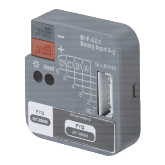
Page 14: Device Overview
Setup and function Device overview BI-F-2.0.x2 Fig. 1: Overview of devices 2-gang binary input, flush-mounted BI-F-4.0.x2 Fig. 2: Overview of devices 4-gang binary input, flush-mounted [1] Label holder [2] Identification LED [3] Device identification during commissioning [4] Bus connection terminal [5] Inputs, 3/5 wires [6] Non-connected line (NC) Product manual 2CKA000073B5465... -
Page 15: Technical Data
Technical data Technical data Designation Value Power supply 21 - 30 VDC Bus subscribers 1 (12 mA) Power loss 0.3 W max. Bus connection terminal, Connection (free@home Bus) screwless. 0.6 - 0.8 mm Line type J-Y(St)Y, 2 x 2 x 0.8 mm Wire stripping 5 - 6 mm Admissible cable length... -
Page 16: Dimensional Drawings
Technical data Dimensional drawings Fig. 3: Dimensions 2-gang binary input, flush-mounted/4-gang binary input, flush-mounted (specifications in mm) Product manual 2CKA000073B5465 │16... -
Page 17: Connection, Installation / Mounting
Connection, installation / mounting Connection, installation / mounting Planning instructions Note Planning and application instructions for the system are available in system ® manual for Busch-free@home . This can be downloaded via www.busch- jaeger.de/en/smarter-home/systems/abb-freehome. Safety instructions Danger - Electric shock due to short-circuit! Risk of death due to electrical voltage of 100 to 240 V during short-circuit in the low-voltage line. -
Page 18: Circuit Diagrams
Connection, installation / mounting Circuit diagrams BI-F-2.0.x2 Fig. 4: Electrical connection 2-gang binary input, flush-mounted BI-F-4.0.x2 Fig. 5: Electrical connection 4-gang binary input, flush-mounted NC 1 Black Grey Brown orange Yellow Table 4: Colour designation Product manual 2CKA000073B5465 │18... -
Page 19: Electrical Connection
Connection, installation / mounting Electrical connection – The bus line connection is established by means of the enclosed bus connection terminal. – The inputs/outputs are connected according to the circuit diagram via six plug-in connecting cables that are approx. 30 cm long. –... -
Page 20: Commissioning
Commissioning Commissioning Commissioning of the device is carried out via the web-based surface of the System Access ® Point Busch-free@home App Next. It is assumed that the basic commissioning steps of the overall system have already been carried out. Knowledge about the basic functions of the commissioning software of the System Access Point is assumed. - Page 21 Commissioning 6.1.1 Add device Configuring, positioning and linking of the devices is carried out via button "Devices, scenes and groups" (switch icon) in the user interface of the System Access Point. If you do not enter via the main menu, the switch icon may only be visible on the left (see arrow).
- Page 22 Commissioning Notice for operation via a mobile phone The building plan/floor plan is not available in the app for mobile phones. – Use the list view of the device configuration here for the location of the device (See “Open overview of devices “ on page 27). Product manual 2CKA000073B5465 │22...
- Page 23 Commissioning The device can be identified via the serial number or via switching. Fig. 8: Allocation of devices A window opens which lists all the devices suitable for the application selected. Identification via serial number Fig. 9: Identification via serial number 5.
- Page 24 Commissioning Identification via switching If several devices are listed in the device list, you can identify them by switching the actual device. Fig. 10: Identification via switching (example illustration) 1. Open the device list. 2. Press the "Identification" button [1] and then switch the actual device. Or, as alternative, press only button [2] in the web interface.
- Page 25 Commissioning Assigning a name Fig. 11: Assigning a name (example illustration) 3. Enter a name that is easy to understand and under which the application is to be displayed later, e.g. "South-wall weather station". 4. Tap the "Save" button to take over the adjustments. –...
-
Page 26: Setting Options Per Channel
Commissioning Setting options per channel General settings and special parameter settings can be made for each channel. The settings are made via the web-based user interface of the System Access Point or the Busch-free@home ® App Next. Select device Fig. 12: Selecting device 1. - Page 27 Commissioning Open overview of devices 1. In the main menu select "Devices, scenes & groups" (toothed-wheel icon) [1]. If you do not enter via the main menu, click on the icon [2]. Fig. 13: Open overview of devices (example illustration) 2.
- Page 28 Commissioning Fig. 14: Overview of devices (example illustration) 3. Tap on a device category. – The list of available devices opens. 4. Tap on the device whose information you want to edit. – A new window with information about the respective device opens. Product manual 2CKA000073B5465 │28...
-
Page 29: Parameters
Commissioning Parameters Information about the device name, the position in the building and additional settings are illustrated in the device menu. Fig. 15: Device menu Product manual 2CKA000073B5465 │29... - Page 30 Commissioning Pos. Description Device name An independent designation for the device can be allocated via the text field. Position By tapping on the drop-down menu you can assign a position to the device in the building structure you defined (e.g. assignment to a room on a certain floor). Sensor configuration The sensor is disabled by activating the checkbox.
-
Page 31: Links
Commissioning Links Configuring, positioning and linking of the devices is carried out via menu "Devices, scenes and groups". Sensors and dimming actuators can be linked with each other. This allows simple On/Off circuits or two-way circuits to be implemented. The link is made via the configuration mode in the building plan of the Web-based user interface of the System Access Point. - Page 32 Commissioning 6.4.1 Linking sensor and actuator Configuring, positioning and linking of the devices is carried out via menu "Devices, scenes and groups". Fig. 16: Linking sensor and actuator (example illustration) 1. Select the sensor [1] in the building plan that is to be linked with the actuator (detailed information is available in the system manual).
- Page 33 Commissioning Light scenes and light groups A light scene means calling up a preset light situation (e.g. preset dimming value) via a single push-button. For a light group, a group of lamps is switched simultaneously by means of a single push-button. Light scenes and light groups can be configured via menu "Devices, scenes &...
-
Page 34: Update
Update Update A firmware update is carried out via the web-based user interface of the System Access Point. Operation Maintenance The device is maintenance-free. In case of damage, e.g. during transport or storage), do not perform repairs. Once the device is opened, the warranty is void. Access to the device must be guaranteed for operation, testing, inspection, maintenance and repairs (according to DIN VDE 0100-520). -
Page 35: Notes
Notes Notes Product manual 2CKA000073B5465 │35... -
Page 36: Index
Index Index sensor ................35 Add device ................24 Allocation of devices ............23 Maintenance ................37 Assigning a name ..............28 Mounting ................21 Circuit diagrams ..............19 Notes ..................38 Cleaning ................37 Notes on the instruction manual ..........3 Commissioning ..............23 Connection, installation / mounting ........ - Page 37 A member of the ABB Group Notice We reserve the right to make Busch-Jaeger Elektro GmbH technical changes at all times as P.O. Box well as changes to the contents of 58505 Lüdenscheid this document without prior notice. Germany The detailed specifications agreed upon apply for orders.
Need help?
Do you have a question about the Busch-free@home BI-F-2.0.x2 and is the answer not in the manual?
Questions and answers