
Related Manuals for Busch-Jaeger 62811 U-WL


Summary of Contents for Busch-Jaeger 62811 U-WL
- Page 1 Product manual │ 05.11.2024 62811 U-WL Switch actuator, 1gang, FM, WL Bra n d i n g -- R e l e a s e 2 0 1 8 - 0 1 - 0 1...
- Page 2 Table of contents Ta b l e o f c o n te n t s Notes on the instruction manual ......................... 4 Trademarks ..............................4 Safety ................................. 5 Information and symbols used ......................5 Intended use ........................... 6 Improper use ........................... 6 Target group / Qualifications of personnel..................
- Page 3 Table of contents Downloading and installing the app ....................34 Identifying the device ........................35 Commissioning in the expansion stage "Device control" ............... 35 Commissioning of the expansion stage "Room control" ..............38 Commissioning of the expansion stage "Home automation" ............41 9.5.1 Authorizations ............................
- Page 4 If you pass the device on, also include this manual along with it. Busch-Jaeger accepts no liability for any failure to observe the instructions in this manual. If you require additional information or have questions about the device, please contact Busch- Jaeger or visit our Internet site at: www.BUSCH-JAEGER.de...
- Page 5 However, residual hazards remain. Read and adhere to the safety instructions to prevent hazards of this kind. Busch-Jaeger accepts no liability for any failure to observe the safety instructions. Information and symbols used The following Instructions point to particular hazards involved in the use of the device or provide...
- Page 6 Each use not listed in Chapter 3.2 “Intended use“ on page 6 is deemed improper use and can lead to personal injury and damage to property. Busch-Jaeger is not liable for damages caused by use deemed contrary to the intended use of the device. The associated risk is borne exclusively by the user/operator.
- Page 7 Safety Target group / Qualifications of personnel 3.4.1 Operation No special qualifications are needed to operate the device. 3.4.2 Installation, commissioning and maintenance Installation, commissioning and maintenance of the device must only be carried out by trained and properly qualified electrical installers. The electrical installer must have read and understood the manual and follow the instructions provided.
- Page 8 Cyber security The industry faces intensifying cyber security risks. In order to increase stability, safety and robustness of its solutions, Busch-Jaeger has formally established cyber security robustness testing as part of the product development process. The following measures are prerequisite for the safe operation of your Busch-free@home ®...
- Page 9 Safety Personal data (also telemetry data) Personal data consists of details regarding the personal or factual circumstances of a certain or identifiable natural person. Information that cannot be connected directly or indirectly to your identity, such as the number of users of a page, is not personal data. In the case myBUSCH-JAEGER these consist of data you have made available to us yourself, such as registration data, contact data, or data added in connection with the services used, such as bank data, as well as data of devices which have been allocated to the user account.
- Page 10 Safety Notice on privacy policies: https://www.busch-jaeger.de/en/privacy-policy Concrete handling of personal data that are obtained, stored and processed by the Busch- free@home ® System Access Point 2.0: Revocation of Description Processing options Obtaining consent consent The name of the user is...
- Page 11 Security check data Can be shared with Busch- Jaeger R&D. R&D can verify The user can exchange protocols on the basis of: protocols with Busch-Jaeger but the automatic exchanged is not Local recording is – Problems at the activated. supported configuration –...
- Page 12 This function can only be used by the Busch-Jaeger technician, not by the end customer. The end customer always has his device under his own control. Without activation by the user/end customer, the interface cannot be used by anyone.
- Page 13 Safety Certificate REST API The Rest API makes it possible for developers to implement own scripts based on JAVA. Scripts that use the local REST interface can be signed via certificate. The System Access Point 2.0 offers the option to generate and download such a certificate. This setting is an option that is only intended for developers.
- Page 14 Safety Safety instructions Danger - Electric voltage! Electric voltage! Risk of death and fire due to electric voltage of 100 … 240 V. Dangerous currents flow through the body when coming into direct or indirect contact with live components. This can result in electric shock, burns or even death.
- Page 15 Information on protection of the environment Information on protection of the environment Environment Consider the protection of the environment! Used electric and electronic devices must not be disposed of with domestic waste. – The device contains valuable raw materials which can be recycled. Therefore, dispose of the device at the appropriate collecting depot.
- Page 16 Setup and function Setup and function The device serves for the remote control of lighting systems. It can be operated as Busch- flexTronics ® wireless device. Also the integration into a Busch-free@home ® wireless system is possible. The device can be combined with other participants of the Busch-free@home ®...
- Page 17 Setup and function Functions 5.1.1 Function overview The following table provides an overview of the possible functions of the device. Icon Function Description Switch actuator Switches connected electric load circuits (e.g. lighting) Push-button When actuated, the contact is closed for a set time (0.1 to 5 seconds) and is then opened again.
- Page 18 Setup and function Icon Function Description Central heating actuator Several room temperature controllers can be linked with the central heating actuator. A threshold value can then be defined for the central heating actuator. Depending on the heating requirement, the linked room temperature controller (see threshold value) switches the central heating actuator on or off.
- Page 19 Technical data Technical data Technical data Description Value – free@home wireless Transmission protocol – Bluetooth Transmission frequency 2.4 - 2.48 GHz WL (wireless) < 15 dBm Maximum transmission power Bluetooth LE (BLE) < 10 dBm Power consumption 0.3 W Connection 230 V AC ±10%, 50/60 Hz LEDi load 400 W/VA...
- Page 20 Technical data Types of load Maximum load at 230 V AC LEDi 400 W/VA 300 VA 2300 VA 2300 VA 3000 W 230 V AC Table:6 Types of load Attention! - Damage to device Risk of damaging the device due to overheating! –...
- Page 21 Connection and installation Connection and installation Planning instructions Note Transmitter and receiver communicate via radio control. The transmission range depends on the structural conditions. Walls and ceilings, especially steel reinforcements or metal claddings, reduce the transmission range. The distance of components to each other and to other transmitters that also emit high- frequency signals (e.g.
- Page 22 Connection and installation Safety instructions Danger - Electric shock due to short-circuit! Risk of death due to electrical voltage of 100 to 240 V during short-circuit in the low-voltage line. – Low-voltage and 100 - 240 V lines must not be installed together in a flush- mounted box! –...
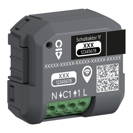
- Page 23 External conductor Neutral conductor ↑1 Extension unit input 1 (optional) ↓C1 Output 1 Fig. 5: Electrical connection 62811 U-WL Requirements for the electrician Danger - Electric voltage! Install the device only if you have the necessary electrical engineering knowledge and experience.
- Page 24 Connection and installation Mounting Notice The device can be mounted in a ceiling box or deep flush-mounted box behind a light switch. Check beforehand whether there is sufficient space. To install the device, perform the following steps: 1. If necessary, remove the already installed flush-mounted insert, (e.g light switch). 2.
- Page 25 Overview of applications Overview of applications The device can be used in three different expansion stages: Device Control (individual control) ■ – The expansion stage takes place as with a conventional switch actuator. The device can additionally be controlled and parameterised with the Busch-free@home ®...
- Page 26 Overview of applications Expansion stage "Device control" This expansion stage contains only one device and no other devices or links. The device can be controlled and parameterised with the Busch-free@home ® Next App. The operation is made as with a conventional switch actuator. The access from the smartphone to the networked device is carried out with Bluetooth via ■...
- Page 27 Overview of applications Expansion stage "Room control" In this expansion stage the configuration, remote control and parameter setting of a switch actuator and additional devices are made with the Busch-free@home ® Next App. Up to 32 devices can be linked with each other in the expansion stage via a mesh network. ■...
- Page 28 Overview of applications Expansion stage "Home automation" In this expansion stage the remote control is made with the Busch-free@home Next App. The ® parameter setting is made in the web-based interface of the System Access Point of a Busch- free@home ®...
- Page 29 Overview of applications Overview Busch-free@home Next App areas ® In the following you see an example of the function and operating areas of the app for the device. Overview area Parameters General settings (Example) (Example) Others (example) Change of device name and the Switching of loads Information about the device and ■...
- Page 30 Overview of applications Overview of start screen Three-point menu The switch menu opens by tapping on the three-point menu (views within illustrations A1 and A2). – Here you can switch the load via the sliding switch / switch [A1]. – You can also open the function "Lock to brightness"...
- Page 31 Overview of applications [A1] Sliding switch / switch for switching the load. [A2] Detail view of function "Lock at brightness. [B1] Detailed view of the drop-down menu for adding an additional device. [C1] Detailed view of the function overview of the Busch-free@home ®...
- Page 32 Overview of applications System requirements The system requirements differ in dependence of the selected expansion stage. The system requirements are available in the following sections. Expansion stage "Device control" ■ – Information about the expansion stage: Chapter 8.1 “Expansion stage "Device control"“ on page 26 –...
- Page 33 Overview of applications 8.7.2 System requirements: "Room control" A mobile terminal device is required for commissioning in the expansion stage "Room control" via the app Busch-free@home ® Next App. In the expansion stage "Room control" the entire project (including device data and timers) can be stored within myBUSCH-JAEGER. In the following the designation "Smartphone"...
- Page 34 Commissioning Commissioning Notice – After being activated, the device is in programming mode and is automatically visible in the app or in the System Access Point for 30 minutes. – As long as the device is in programming mode, the LED on the device flashes.
- Page 35 Commissioning Identifying the device Before commissioning, the device can be identified in the Busch-free@home Next App for 30 ® minutes after a voltage reset. This function is especially helpful when several device are made operational at the same time. Tor identify a device, proceed as follows: 1.
- Page 36 Commissioning Fig. 11: Integrating the device [D] - [F] (example illustration) 5. Select “New installation” when there is none yet [D]. – Select the desired installation type and confirm with "Continue" [E]. – Assign a name for the new installation and select "Continue". –...
- Page 37 Commissioning Fig. 12: Integrating the device [G] - [H] (example illustration) 7. The app indicates that the device was added successfully to the installation [H]. Complete the process via "Finished" or, if necessary, repeat the steps via the option "Add an additional device".
- Page 38 Commissioning Commissioning of the expansion stage "Room control" To connect the device with the app, proceed as follows. 1. Activate the Bluetooth on your smartphone and connect the device to the power supply. Fig. 13: Integrating the device [A] - [C] (example illustration) 2.
- Page 39 Commissioning Fig. 14: Integrating the device [D] - [F] (example illustration) 5. Select “New installation” when there is none yet [D]. – Select the desired installation type and confirm with "Continue" [E]. – Register yourself at myBUSCH-JAEGER [F]. – Assign a name for the new installation and select "Continue". –...
- Page 40 Commissioning Fig. 15: Integrating the device [G] - [H] (example illustration) 6. Assign a new device name and position the device inside the installation with the help of the plus icon (specification of floor and room). Then confirm the settings with "Continue" [G]. –...
- Page 41 Commissioning Commissioning of the expansion stage "Home automation" Notice – It is assumed that the basic commissioning steps of the overall system have already been carried out. – Knowledge about the basic functions of the app and the System Access Point is assumed.
- Page 42 Commissioning Fig. 17: Coupling wireless devices with the System Access Point 5. Tap on the "Search for devices" button and then on the "Search" button in the "Search for wireless devices" window. – Close the notification window "Search for wireless devices" by clicking on "OK". –...
- Page 43 Commissioning 9.5.3 Add device Fig. 18: Devices, scenes and groups 1. Select "Devices, scenes & groups" via the main menu or the page menu in the user interface of the System Access Point. – The "Building plan" opens. Fig. 19: Opening the building plan and list of components (example illustration) 2.
- Page 44 Commissioning Fig. 20: Pulling the device out of the menu bar (example illustration) 4. Select the desired device and pull it into the building plan via drag-and-drop. – If you pull a new device into a room via drag-and-drop, a pop-up window opens in which all devices that are located in the system are listed and which have not been allocated to a room.
- Page 45 Commissioning The device can be identified via the serial number or via switching. Fig. 22: Allocation of devices A window opens which lists all the devices suitable for the application selected. Identification via serial number Fig. 23: Identification via serial number 6.
- Page 46 Commissioning Identification via switching If several devices are listed in the device list, you can identify them by switching the actual device. Fig. 24: Identification via switching (example illustration) 1. Open the device list. 2. Press the "Identification" button [1] and then switch the actual device. Or, as alternative, press only the button [2] in the web interface.
- Page 47 Commissioning Assigning a name Fig. 25: Assigning a name (example illustration) 3. Enter a name that is easy to understand and under which the application is to be displayed later, e.g. "South-wall weather station". 4. Tap on the "Save" button to take over the adjustments. –...
- Page 48 Commissioning Fig. 26: Integrating the device [A] - [C] (example illustration) 1. Tap the plus icon [A]. 2. Select "Add a new Bluetooth device” [B] and confirm with "Continue”. 3. Tap on "Scan QR code” [C]. 4. Use the camera of your smartphone to scan the printed QR code on the rear side of the device.
- Page 49 Commissioning Fig. 27: Integrating the device [D] - [F] (example illustration) 5. Select “New installation” when there is none yet [D]. – Select the desired installation type and confirm with "Continue" [E]. – Assign a name for the new installation and select "Continue". –...
- Page 50 Commissioning Fig. 28: Integrating the device [G] - [H] (example illustration) 7. The app indicates that the device was added successfully to the installation [H]. Complete the process via "Finished" or, if necessary, repeat the steps via the option "Add an additional device".
- Page 51 Operation Operation 10.1 Display elements Fig. 29: Display elements [A] LED Status LED Status Description The device and the connected load flash five times because the function 5 flashes “Identify” was activated. Flashing The device is in programming mode. Table. 9: Conditions of status LED Product manual 2CKA000073B0083 │51...
- Page 52 Operation 10.2 Overview of parameters For the configuration of the parameters, select the installation and the desired device. Then scroll down to the parameters. The overview shows the individual parameters in their sequence of appearance during operation. Notice Some changes must, if necessary, be saved via the "Save" button for them to become effective.
- Page 53 Operation 10.2.1 Overview of actuator parameters Channel name Here an individual name can be assigned to the channel. Icon Here you can change the icon with which the actuator is portrayed. Function The extension unit input is linked with the actuator channel at the factory. If the function “Switch actuator”...
- Page 54 Operation 10.2.2 Overview of sensor parameters Notice The device is a an actuator. On the extension unit input a conventional button can be wired and configured here. Also the connection of a Sub-insert flex is possible. Channel name Here an individual name can be assigned to the channel. Block local operation With this function the operation can be deactivated via the button.
- Page 55 Operation Sensor type This sensor type is intended for operation with a mechanical push-button. Push-button The actuator status is inverted with every activation of the input (only rising edge). Reverser and push-button invert the existing status of the actuator. With this type of sensor a classic 2 way circuit can be implemented.
- Page 56 Operation 10.3 Automation/Timer Notice The device is not equipped with batteries. – Time programs are stopped at a power failure. – The time in the device is synchronized again only at the next connection with the app. Up to 28 switching times can be programmed via the automation. Each timer has a weekday function and can be programmed for one or several weekdays.
- Page 57 Operation 10.3.1 Automation/Timer settings Different switching times can be programmed in the automation area. The following overview shows the setting options and parameters in their sequence of appearance during operation. Notice Performed changes must, if necessary, be saved via the "Save" button for them to become effective.
- Page 58 Operation Repetition on every Mon/Tue/Wed/Thu/Fri/Sat/Sun Specifying the weekdays at which the timer is to repeat itself. The standard setting. The timer switches on all weekdays at Switching on all weekdays the same time. Live mode If the live-mode is activated, at the change of the configuration the actuator changes into the timer settings to display the configured switching state.
- Page 59 Operation 10.4 General settings The name of the device can be changed in the "General settings" and the position (floor/room) inside the house can be defined. General settings General settings Expansion stage Room control and Home Expansion stage Device control automation Table.
- Page 60 Operation 10.5 Settings / maintenance Settings / maintenance Settings / maintenance Expansion stage Room control and Home Expansion stage Device control automation Information about the device Information about the device [1] Overview of the device data [1] Overview of the device data Maintenance Maintenance [2] Setting and changing device password...
- Page 61 Operation 10.6 Firmware update The Busch-free@home Next App on the start page shows the notification "Device update ® available" when a new firmware is available for your device. To perform the update, proceed as follows: 1. Under the notice "Device update available" tap on "Update now". 2.
- Page 62 Access to the device must be guaranteed for operation, testing, inspection, maintenance and repairs (according to DIN VDE 0100-520). Declaration of conformity Busch-Jaeger herewith declares, that radio system type 62811 U-WL conforms to directive 2014/53/EU. The complete text of the EU Declaration of Conformity is available at the following Internet...
- Page 63 Index Index Information on protection of the environment ......15 Intended use ................6 Add device................43 Assigning a name ..............47 Authorizations ................41 Maintenance ................62 Automation/Timer ............. 30, 56 Mounting ...................24 Automation/Timer settings ............57 Notes on the instruction manual ..........4 Circuit diagrams ..............23, 24 Commissioning ................34 ”Scanning the QR code”...
- Page 64 Index Product manual 2CKA000073B0083 │64...
- Page 65 Busch-Jaeger Elektro GmbH A member of the ABB Group Freisenbergstraße 2 D-58513 Lüdenscheid, Germany www.BUSCH-JAEGER.de Customer service: Tel.: +49 2351 956-1600 Copyright © 2024 Busch-Jaeger Elektro GmbH All rights reserved...
Need help?
Do you have a question about the 62811 U-WL and is the answer not in the manual?
Questions and answers