
Related Manuals for Busch-Jaeger Busch-free@home 6211/1.1-WL


Summary of Contents for Busch-Jaeger Busch-free@home 6211/1.1-WL
- Page 1 2CKA001473B9185 │ 05.12.2018 Product manual Busch-free@home ® Sensor/Switch actuator 1/1gang; 2/1gang; 2/2gang, wireless 6211/1.1-WL 6211/2.1-WL...
-
Page 2: Table Of Contents
Table of contents Table of contents Information on the manual ..........................4 Safety ................................. 5 Information and symbols used ......................5 Intended use ............................6 Improper use ............................6 Target group / Qualifications of personnel ................... 6 Safety instructions ..........................7 Environment ............................ - Page 3 Table of contents Notes ................................35 Index ................................36 Product manual 2CKA001473B9185 │3...
-
Page 4: Information On The Manual
If you pass the device on, also pass on this manual along with it. Busch-Jaeger accepts no liability for any failure to observe the instructions in this manual. If you require additional information or have questions about the device, please contact Busch- Jaeger or visit our Internet site at: www.busch-jaeger.de/freeathome... -
Page 5: Safety
However, residual hazards remain. Read and adhere to the safety instructions to prevent hazards of this kind. Busch-Jaeger accepts no liability for any failure to observe the safety instructions. Information and symbols used The following Instructions point to particular hazards involved in the use of the device or provide... -
Page 6: Intended Use
Each use not listed in Chapter 2.2 “Intended use“ on page 6 is deemed improper use and can lead to personal injury and damage to property. Busch-Jaeger is not liable for damages caused by use deemed contrary to the intended use of the device. The associated risk is borne exclusively by the user/operator. -
Page 7: Safety Instructions
Safety Safety instructions Safety instructions Danger - E lec tric voltage! Electric voltage! Risk of death and fire due to electric voltage of 100 … 240 V. Dangerous currents flow through the body when coming into direct or indirect contact with live components. This can result in electric shock, burns or even death. -
Page 8: Setup And Function
Setup and function Environment Setup and function Fig. 1: Product overview [1] Flush-mounted insert [2] Sensor for sensor/switch actuator, 1/1gang [3] Sensor for sensor/switch actuator, 2/1gang and 2/2gang [4] Cover frame (not included in scope of delivery) [5] Rocker (not included in scope of delivery) This device is a sensor/switch actuator unit for decentralized flush-mounted installation. -
Page 9: Scope Of Supply
It must still be completed with a suitable rocker [5] and a cover frame [4]. Note Depending on their use, the rockers can be selected with different printing. ■ Additional information about the switch ranges is available in the electronic catalogue (www.busch-jaeger-katalog.de). Overview of types Ac tuator Artic le no. P roduc t name... -
Page 10: Device Overview
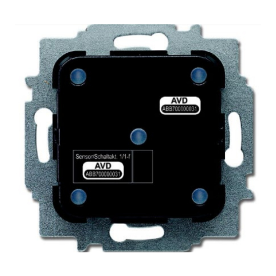
Setup and function Device overview Device overview Fig.2: Device overview of sensor/switch actuator Phase sensing L [6] Mark TOP [7] Multi-point connector [8] Terminal block Fig. 3: Sensors [1] Sensor for sensor/switch actuator, 1/1gang [2] Sensor for sensor/switch actuator, 2/1gang and 2/2gang Product manual 2CKA001473B9185 │10... -
Page 11: Technical Data
Technical data Types of load Technical data Des ignation V alue Operating voltage 230 V AC, 50/60 Hz L, N (option), inputs and outputs non- floating Screw-type terminal: Connection 2 x 2.5 mm² rigid; 2 x 1.5 mm² flexible With protective cover and reset Claw (removable) Transmission protocol... -
Page 12: Dimensional Drawings
Technical data Dimensional drawings Dimensional drawings NOT E All dimensions are specified in mm. All device types listed in this manual have the same dimensions. Fig. 4: Dimensions of all described device types (all dimensions in mm) Product manual 2CKA001473B9185 │12... -
Page 13: Connection And Installation
Connection and installation Planning instructions Connection and installation Planning instructions Note Planning and application instructions for the system are available in system manual for Busch-free@home ® . This can be downloaded via www.busch- jaeger.de/freeathome. Note Transmitter and receiver communicate via radio control. The transmission range depends on the structural conditions. -
Page 14: Safety Instructions
Connection and installation Safety instructions Safety instructions Danger - E lec tric s hoc k due to s hort-c irc uit! Risk of death due to electrical voltage of 100 … 240 V during short-circuit in the low-voltage conduit. – Low-voltage and 100 …... -
Page 15: Circuit Diagrams
Connection and installation Circuit diagrams Circuit diagrams 10 A 10 A 10 A Fig. 5: Electrical connection Ⓐ 6211/1.1-WL Ⓑ 6211/2.1-WL Ⓒ 6211/2.2-WL Product manual 2CKA001473B9185 │15... -
Page 16: Installation
Connection and installation Installation Installation Note The devices have been prepared for installing in flush-mounted boxes in connection with the corresponding mounting plate. The device insert has already been inserted in the mounting plate. To install the device, perform the following steps: Note The sensor must be pulled off the flush-mounted insert before mounting! Note... - Page 17 Connection and installation Installation 6. Attach the cover (with mounted sensor) to the flush-mounted insert. Observe the correct position of the sensor connection [1]. Fig. 9: Mounting the sensor Product manual 2CKA001473B9185 │17...
-
Page 18: Commissioning
Commissioning Installation Commissioning Commissioning of the device is always carried out via the Web-based surface of the System Access Point. It is assumed that the basic commissioning steps of the overall system have already been carried out. Knowledge about the Web-based commissioning software of the System Access Point is assumed. -
Page 19: Coupling Of Wireless Devices With The System Access Point
Commissioning Coupling of wireless devices with the System Access Point Coupling of wireless devices with the System Access Point free@home wireless devices must first be coupled with the System Access Point before they can be used in a project. The devices exchange a security key during the coupling process. Communication between devices is carried out encrypted after coupling and they are firmly connected with the System Access Point. - Page 20 Commissioning Coupling of wireless devices with the System Access Point 2. Keep the button at the bottom left pressed. 3. Re-energize the device. The LED flashes slowly for 10 seconds, then fast for 5 seconds and then goes out. The factory settings are restored and the device can now be programmed again. Note Devices which are already in factory settings are not reset again.
-
Page 21: Allocation Of Devices And Definition Of Channels
Commissioning Allocation of devices and definition of channels Allocation of devices and definition of channels The devices connected to the system must be identified, i.e. they are allocated to a room according to their function and are given a practical name. The allocation is made via the allocation function of the Web-based user interface of the System Access Point. - Page 22 Commissioning Allocation of devices and definition of channels Fig. 12: Pop-up window with the suitable devices Identific ation The device can be identified via the serial number or via switching. Identific ation via s erial number Fig. 13: Identification via serial number Product manual 2CKA001473B9185 │22...
- Page 23 Commissioning Allocation of devices and definition of channels Compare the serial number and the short ID of the identification label, which is glued on the ■ device, with the numbers and IDs in the list. This is how the searched for device and possibly the searched for channel are identified.
- Page 24 Commissioning Allocation of devices and definition of channels Identific ation via s witc hing (only s uitable for ac tuators ) Fig. 14: Identification via switching 1. Select a device and a channel from the list. 2. Press the button in the detailed view of the device. The connected load is switched.
- Page 25 Commissioning Allocation of devices and definition of channels S pec ifying a name Fig. 15: Specifying a name 1. Enter a name that is easy to understand and under which the application is to be displayed later, (e.g. "Ceiling light" or "Living room blind"). 2.
-
Page 26: Setting Options Per Channel
Commissioning Setting options per channel Setting options per channel General settings and special parameter settings must be made for each channel. The settings are made via the allocation function of the Web-based user interface of the System Access Point. S elec t devic e Fig. -
Page 27: Settings - Overview Of Setup Menus
Commissioning Setting options per channel 6.3.1 Settings – Overview of setup menus 6.3.1.1 P arameter s ettings of 1/1gang s ens or/s witc h ac tuator Ac tuator s ettings [1] Changing the name [2] Deleting the channel [3] Switching the actuator via the button [4] Selection of a different icon [5] Setting the switch-off delay in seconds –... - Page 28 Commissioning Setting options per channel R oc ker s ettings Icon of the application [1] Changing the name [2] Switching of the sensor via the button [3] Setting the LED night/day switch-on brightness in % via the -/+ buttons – The parameter specifies how strong the LED lights up percentage wise during night/day.
- Page 29 Commissioning Setting options per channel For all other devices it becomes available only after being linked with an actuator. The setting in the list view is then made via the linking function of the Web-based user interface of the System Access Point.
-
Page 30: Parameter Settings Of 2/1Gang Sensor/Switch Actuator
Commissioning Setting options per channel 6.3.1.2 P arameter s ettings of 2/1gang s ens or/s witc h ac tuator Ac tuator s ettings As for 1/1gang. S ens or s ettings As for 1/1gang. However, two rockers (left and right rocker) are displayed in the list view. R oc ker s ettings As for 1/1gang. -
Page 31: Links
Commissioning Links Links The sensors and actuators created via the allocation function can now be linked with each other. This allows simple switch-off circuits or two-way circuits to be implemented. The linking in the list view is made via the linking function of the Web-based user interface of the System Access Point. - Page 32 Commissioning Links Fig. 22: Linking an actuator with an additional sensor 1. On the working area select the second sensor [1] that is to be linked with the actuator. 2. Select the actuator [2] that is to be served by the sensor. 3.
-
Page 33: Update
Additional information about the switch ranges is available in the electronic catalogue (www.busch-jaeger-catalogue.com). Maintenance The device is maintenance-free. In case of damage, e.g. during transport or storage), do not perform repairs. -
Page 34: Diagnosis Of Faults
Maintenance Diagnosis of faults Diagnosis of faults If the device does not function correctly, the L leading edge control can be measured via the phase sensor (L) and determined whether the device carries current after being connected. If it carries current, the cause of the fault is not the electronic insert. Fig. - Page 35 Notes Diagnosis of faults Notes Product manual 2CKA001473B9185 │35...
- Page 36 Index Diagnosis of faults Index Actuator ..................9 Operation ................33 Add device ................21 Overview of types ..............9 Allocation of devices .............. 21 Parameter settings Circuit diagrams ............... 15, 16 Sensor/switch actuator, 1/1gang ........27 Cleaning ................. 33 Sensor/switch actuator, 2/1gang ........
- Page 37 Tel.: +49 2351 956-1600 document and its contents, or Fax: +49 2351 956-1700 extracts thereof, must not be reproduced, transmitted or reused by third parties without prior written consent by ABB Copyright 2018 Busch-Jaeger Elektro GmbH © All rights reserved...
Need help?
Do you have a question about the Busch-free@home 6211/1.1-WL and is the answer not in the manual?
Questions and answers