
Subscribe to Our Youtube Channel
Related Manuals for Fronius FCU-20.O


Summary of Contents for Fronius FCU-20.O
- Page 1 / Perfect Welding / Solar Energy / Perfect Charging Operating Instructions FCU-20.O Control unit FCU-20 42,0426,0103,EN V05 - 06072016...
- Page 3 Safety rules DANGER! “DANGER!” indicates an imminently hazardous situation which, if not avoided, will result in death or serious injury. This signal word is to be limited to the most extreme situations. This signal word is not used for property damage hazards unless personal injury risk appropriate to this level is also involved.
- Page 4 General remarks Any malfunctions which might impair machine safety must be eliminated (continued) immediately - meaning before the equipment is next switched on. It’s your safety that’s at stake! Utilisation for The machine may only be used for jobs as defined by the “Intended intended purpose purpose”.
- Page 5 Obligations of Before starting work, all persons to be entrusted with carrying out work with personnel (or on) the machine shall undertake to observe the basic regulations on workplace safety and accident prevention to read the sections on “safety rules” and the “warnings” contained in this manual, and to sign to confirm that they have understood these and will comply with them.
- Page 6 Protection for “Protective clothing” also includes: yourself and protecting your eyes and face from UV rays, heat and flying sparks with other persons an appropriate safety shield containing appropriate regulation filter glass (continued) wearing a pair of appropriate regulation goggles (with sideguards) behind the safety shield wearing stout footwear that will also insulate even in wet conditions protecting your hands by wearing appropriate gloves (electrically insula-...
- Page 7 Hazards from The harmfulness of the welding fumes will depend on e.g. the following noxious gases components: and vapours the metals used in and for the workpiece (continued) the electrodes coatings cleaning and degreasing agents and the like For this reason, pay attention to the relevant Materials Safety Data Sheets and the information given by the manufacturer regarding the components listed above.
- Page 8 Hazards from Do not loop any cables or other leads around your body or any part of your mains and weld- body. ing current (continued) Never immerse the welding electrode (rod electrode, tungsten electrode, welding wire, ...) in liquid in order to cool it, and never touch it when the power source is ON.
- Page 9 Stray welding When using current supply distributors, twin head wire feeder fixtures etc., currents please note the following: The electrode on the unused welding torch/welding (continued) tongs is also current carrying. Please ensure that there is sufficient insula- ting storage for the unused welding torch/tongs. In the case of automated MIG/MAG applications, ensure that only insulated filler wire is routed from the welding wire drum, large wirefeeder spool or wirespool to the wirefeeder.
- Page 10 EMI Precautions Electromagnetic fields may cause as yet unknown damage to health. Effects on the health of persons in the vicinity, e.g. users of heart pace- makers and hearing aids Users of heart pacemakers must take medical advice before going anywhere near welding equipment or welding workplaces Keep as much space as possible between welding cables and head/body of welder for safety reasons...
- Page 11 Particular danger When hoisting the machines by crane, only use suitable manufacturer- spots supplied lifting devices. (continued) Attach the chains and/or ropes to all the hoisting points provided on the suitable lifting device. The chains and/or ropes must be at an angle which is as close to the vertical as possible.
- Page 12 Safety precauti- A machine that topples over can easily kill someone! For this reason, always ons at the instal- place the machine on an even, firm floor in such a way that it stands firmly. lation site and An angle of inclination of up to 10° is permissible. when being transported Special regulations apply to rooms at risk from fire and/or explosion.
- Page 13 Safety precauti- If any damage occurs in cases where other coolants have been used, the ons in normal manufacturer shall not be liable for any such damage, and all warranty operation claims shall be null and void. (continued) Under certain conditions, the coolant is flammable. Only transport the coolant in closed original containers, and keep it away from sources of ignition.
- Page 14 Safety markings Equipment with CE-markings fulfils the basic requirements of the Low- Voltage and Electromagnetic Compatibility Guideline (e.g. relevant product standards according to EN 60 974). . Equipment marked with the CSA-Test Mark fulfils the requirements made in the relevant standards for Canada and the USA. Data security The user is responsible for the data security of changes made to factory settings.
-
Page 15: Table Of Contents
Table of contents General ................................5 Device concept ............................5 Field of application FCU 20 ........................5 Field of application FCU 20.O ........................5 Control elements ............................6 Control elements ............................6 Control panel .............................. 6 Rear view ..............................7 Touchscreen display ............................. - Page 16 System overview ............................35 Installation kit ............................35 Pedal remote control ..........................35 Connecting lead ............................35 Spare parts list FCU-20.O ........................... 36 FCU-20.O spare parts list......................... 36 Accessories and options FCU20.O ......................38 System overview ............................38 Installation kit ............................38 Pedal remote control ..........................
-
Page 17: General
FCU-20 control unit Field of The FCU-20 control unit is intended exclusively for use with the Fronius FTT-10/ 40/ 150/ application 300 and FRT-50/ 150 rotation tables. FCU 20 It can be used in the following welding processes:... -
Page 18: Control Elements
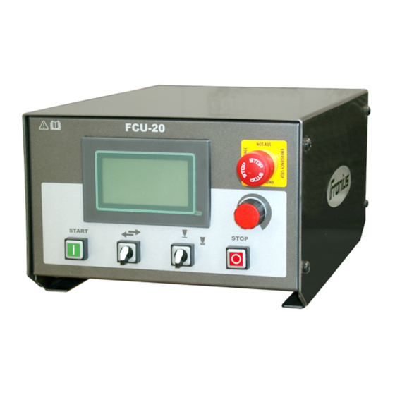
Control elements Control elements WARNING! Operating the equipment incorrectly can cause serious injury and damage. Do not use the functions described here until you have thoroughly read and understood the following documents: these operating instructions all operating instructions for the system components Control panel FCU-20 control panel... -
Page 19: Rear View
Control panel (5) Welding ON/OFF selector switch (continued) For choosing whether to run the automatic program sequence with or without weld- ing. Important! Welding can also be activated/deactivated using the "Welding ON/OFF" parameter. (6) Manual mode button To move the face plate manually. Press and hold the button for more than seven seconds to change to the maximum traversing speed. - Page 20 Rear view (14) Motor cable output (continued) Control line to the rotation table (3.5 m). (15) "FRC-1 connecting plug" option Start/Stop function via remote control (16) Power source B connecting plug Connection to the relevant power source (17) Power source A connecting plug Connection to the relevant power source (18) Mains cable output Mains cable (5 m)
-
Page 21: Touchscreen Display
The touchscreen display consists of an analogue resistive layer covered by a protec- tive film. Remove the protective film if it becomes heavily soiled and attach a new one. The item number of the film can be found in the FCU-20 spare parts list. Important! Fronius accepts no liability for damage arising from working without a protective film. This also applies if the damage occurs during the device's guarantee period. To use the touchscreen display, gently press the relevant button on the display with your finger. -
Page 22: Parameter Entry Options
Parameter entry options General Some parameters can be amended during an automatic program sequence. The amend- ed values are applied immediately, but are not saved in the currently loaded program. Multifunction To use the multifunction wheel, proceed as follows: wheel Move the cursor (black rectangle) to the parameter that you wish to change by turn- ing the multifunction wheel. -
Page 23: Menu Navigation
Menu navigation Navigating On the process parameter pages, the user can scroll back and forth using the following through process controls: parameter pages Touch buttons - Scroll to the next page - Scroll to the previous page - Escape to main menu (parameter page 1) Multifunction Line change: wheel... -
Page 24: List Of Parameters
List of parameters Process Parameter designation Setting range parameters Direction << >> Clockwise rotation, anti-clockwise rotation Rotation speed rpm (depends on rotation table) Welding ON / OFF Operation 2-step Downslope 0.0 - 60.0 s Crater-filling 0.0 - 60.0 s Start-up delay 0.0 - 60.0 s Flying Start 0.0 - 60.0 s... -
Page 25: Description Of Process Parameters
Description of process parameters General A whole range of parameters must be coordinated to ensure that the various compo- nents in the power source and control unit work together properly. These parameters are referred to as process parameters, and contain mainly information for the fine-tuning of the components (devices) used. Parameter page 1 (1) Direction <<... -
Page 26: Parameter
Parameter page 2 (1) Welding ON/OFF For preselecting whether to run the automatic program sequence with or without welding. The welding ON/OFF selector switch (5) must also be switched to "ON" during a sequence where welding takes place. Unit: Setting range: OFF / ON Factory settings (2) 2-step mode... -
Page 27: Parameter
Parameter page 3 (1) Downslope Duration of welding movement in the welding current downslope phase. Welding current The rotation table continues to move (2-step) after the end point of the weld (deter- mined by cam). The downslope for the welding current must be set at the power source. -
Page 28: Parameter
Parameter page 4 (1) Start-up delay ...Time between arc ignition and the Welding current start of welding movement. Unit: Setting range: 0.0 - 60.0 Movement Factory setting: rotation table ...Start-up delay (2) Flying-start ... Time delay between the start of the rotational movement and the igni- Movement tion of the arc. -
Page 29: Parameter
Parameter page 5 (1) Cooling time Length of time that the torch Welding current should dwell over the end of the weld seam to allow the seam to cool under the shielding gas. Once this cooling Movement time has elapsed, the time for crater rotation table filling starts. -
Page 30: Parameter
Parameter page 6 (1) Return travel ON/OFF Activates/deactivates the automatic Return travel return travel of the rotation table from the end point of the weld to the start Welding path point. Return travel takes place at high speed, and with no welding. Unit: S ...Start point of the weld E ...End point of the weld... -
Page 31: Parameter
Parameter page 7 (1) 2 power sources option - power source A Activates/deactivates power source A. "2 power sources option"..optional parameter for controlling two power sources. Important! Service parameter "DOWN" must be set to ON to activate or deactivate power source A (see Service parameters). -
Page 32: Parameter Calibration
Parameter calibration General To accelerate the whole process, it is advisable to calculate the parameter values auto- matically. The following parameters can be coordinated: Speed of rotation in rpm Workpiece diameter in mm Welding speed in cm/min Note! Two values are always required to calculate a parameter. Procedure Press the value for speed of rota- tion;... -
Page 33: Program Management
Program management General The FCU-20 control unit allows the user to save and load up to 99 complete parameter lists. The working parameters created for one single component can be saved using a program number selected by the user. These parameter lists can be reloaded at any time, and corrected as required. -
Page 34: Loading Welding Programs
Loading welding 1. Briefly press the touch button for programs loading programs (folder symbol) - the "Load program" page appears. 2. Press the program number field, the numerical pad opens. Enter the desired program number using the numerical pad and confirm by pressing Enter. Alternatively, press the previously selected value again. Press the "Load OK" touch button to load the selected program. -
Page 35: Segment Mode
Segment mode General Welding programs may also be linked in order to cover more complex requirements (see page 15, point 3). This is always necessary if different welding parameters are required for a particular section of a welding path, or various other settings are required. The FCU-20 control unit provides two segment modes (Segment ON, Segment OFF) as described below. -
Page 36: Segment Off Mode
Segment OFF NOTE! The functions described here are only available in conjunction with the mode "Rob 3000" interface. Program. 7 Program. 8 Program. 25 SEG. OFF SEG. OFF SEG. OFF S..Start automatic procedure (Start button) E..End of automatic procedure ...Main current ..Cam Program chain in SEGMENT OFF mode with Rob 3000 interface Segment OFF... -
Page 37: Service Parameters
Service parameters General The FCU-20 control unit service parameters provide the user with the following options: Display the PLC inputs and outputs Select the preferred language for the display (German, English, Spanish or Italian) Calibrate the command and actual values for traversing path and speed Direction preselection Robot interface activation option Activate 2 power sources option... -
Page 38: Plc List Of Inputs And Outputs
PLC list of inputs Status of PLC inputs and outputs and outputs 24V DC PLC inputs Multifunction wheel A Multifunction wheel B Manual mode button - ES segment (Prg. step) Reserve Manual mode button + Limit switch 360 ° Emergency stop Start button Stop button Welding On/Off... -
Page 39: Parameter Page 3 - Power Source
Parameter page 2 (2) Contrast - Language selec- Press this button to open the "Display" selection window. Press the desired display tion (continued) parameter to select it. The respective adjustment window then opens. Increase or decrease the display contrast or brightness value by pressing + or -. Changed values are reflected immediately on the display. Once the correct setting has been made, press the Escape button to apply the settings. -
Page 40: Parameter Page 4 - Calibration
Parameter page 4 - Calibration Calibration parameters (1) Direction Manual mode + automatic mode direction. The direction can be changed, for exam- ple when the rotation table is in a specific position. (2) MFaktor Multiplication factor - Defines the maximum speed of rotation of the rotation table. (3) FRC 1 Preselect "Inching mode" or "Permanent operation". Parameter page 5 - Hardware Hardware parameters (1) Output voltage Output voltage - for matching the control unit to whichever hardware is connected... -
Page 41: Decommissioning
Calculating the MFaktor: FTT 40/MA Art.No.: On the rating plate of the rotation table, A-4600 Wels the value V is specified. The value of www.fronius.com Ser.No.: MFaktor results according to the following EN 12100 formula: x 1000 230 V 0,8 A... -
Page 42: Troubleshooting
Contact Fro- because of an emergency. nius service personnel. Fault in the installed frequency converter. Contact Fronius service personnel. Screen Number Error Screen No. Er- See page 24 - Language selection: this error can be caused by pressing "..."... - Page 43 Error messages No current flow signal No current (continued) No current flow signal detected from the power source (no volt- flow signal age connection) Cause: Remedy: No arc ignition Clean surface of the workpiece, re-ignite the arc Fault on the power source Check power source settings and correct if necessary No robot interface in use Integration of ROB3000 robot interface Faulty connection to power source Check connection to the power source...
-
Page 44: Technical Data
Technical data FCU-20 technical Mains voltage 230 V data Mains frequency 50/60 Hz Mains fuse 1.5 A Control voltage 24 V Power consumption 230 VA Nominal current Dimensions (l x w x h) 350 x 235 x 160 Weight 5 kg Rating plate FCU- 20 / 20.O... -
Page 45: Spare Parts List Fcu-20
Spare parts list FCU-20 FCU-20 spare 38,0102,0048 parts list 38,0002,0056 38,0002,0061 38,0008,0065 38,0002,0092 4,085,185 38,0002,0090 42,0406,0102 38,0002,0098 42,0406,0093 38,0002,0093 38,0002,0097 38,0002,0091 38,0002,0095 38,0002,0090 38,0002,0098 38,0002,0090 38,0002,0098 38,0002,0098 38,0102,0017 38,0102,0047 43,0001,1115 38,0006,0087 38,0102,0049 4,085,184 38,0006,0087 Rob 3000 38,0101,0014 43,0004,3206 38,0100,0219 38,0100,0187... - Page 46 FCU-20 spare Item number Name parts list 8,040,073 FCU-20 (continued) 4,085,184 TP FCU/FRC PC board 4,085,185 DGP PC board 38,0102,0049 MP FCU-20 38,0002,0061 N.C. contact element emergency stop 38,0002,0090 N.O. contact element 38,0002,0091 N.C. contact element 38,0002,0092 Start button 38,0002,0093 Stop button 38,0002,0095 Toggle switch...
-
Page 47: Accessories And Options Fcu-20
Accessories and options FCU-20 System overview I-kits FCU-20 LEGEND: I-kit Activation FRC-1: 8,100,112 - - - - - - Option I-kit Welding step-axis: 8,100,151 ______ Standard Emergency stop (included in delivery) I-kit Job switch: 8,100,113 I-kit Activation FRT 150: 8,100,125 (Cable for turntable included) 8,100,152 Start for external device... -
Page 48: Spare Parts List Fcu-20.O
Spare parts list FCU-20.O FCU-20.O spare 38,0102,0048 parts list 38,0002,0056 38,0002,0061 38,0008,0065 38,0002,0092 4,085,185 38,0002,0090 42,0406,0102 38,0002,0098 42,0406,0093 38,0002,0093 38,0002,0097 38,0002,0091 38,0002,0095 38,0002,0090 38,0002,0098 38,0002,0090 38,0002,0098 38,0002,0098 38,0006,0210 38,0102,0047 43,0001,1115 38,0006,0087 38,0102,0049 4,085,184 38,0003,0015 38,0003,0017 38,0003,0185 38,0003,0029 Rob 3000 38,0101,0014... - Page 49 FCU-20.O spare Item number Name parts list 8,040,073,630 FCU-20.O (continued) 4,085,184 TP FCU/FRC PC board 4,085,185 DGP PC board 38,0102,0049 MP FCU-20 38,0002,0061 N.C. contact element emergency stop 38,0002,0090 N.O. contact element 38,0002,0091 N.C. contact element 38,0002,0092 Start button 38,0002,0093...
-
Page 50: Accessories And Options Fcu20.O
Accessories and options FCU20.O System overview I-kits FCU-20.O LEGEND: I-kit Activation FRC-1: 8,100,112 - - - - - - Option I-kit Welding step-axis: 8,100,151 ______ Standard Emergency stop (included in delivery) I-kit Job switch: 8,100,113 8,100,152,630 Start for external device... -
Page 51: Eu Declaration Of Conformity Fcu20
EU Declaration of conformity FCU20... -
Page 52: Eu Declaration Of Conformity Fcu20.O
EU Declaration of conformity FCU20.O... -
Page 53: Circuit Diagrams
Circuit diagrams • FCU-20 • FCU-20.O... - Page 88 Spare parts recommendation, FCP 600 - II Mechanical spare parts...
- Page 89 FRONIUS INTERNATIONAL GMBH TechSupport Automation E-Mail: support.automation@fronius.com www.fronius.com www.fronius.com/addresses...
- Page 90 Spare parts recommendation, FCP 600 - II Mechanical spare parts...
Need help?
Do you have a question about the FCU-20.O and is the answer not in the manual?
Questions and answers