Table of Contents
Advertisement
Quick Links
Advertisement
Table of Contents

Related Manuals for National Instruments cRIO-9805


Summary of Contents for National Instruments cRIO-9805
- Page 1 Getting Started 2024-02-07...
-
Page 2: Table Of Contents
Disconnecting Power from the cRIO-9805........ -
Page 3: Getting Started With The Crio-9805
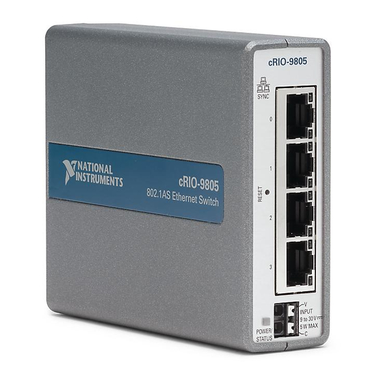
Getting Started Getting Started with the cRIO-9805 This document provides information to help you get started with the cRIO-9805, connecting the module to power, connecting to Ethernet, and configuring the device and the network. Figure 1. cRIO-9805 Front Panel... - Page 4 Getting Started Table 2. Power/Status LED Indicators LED Color LED Pattern Indication Blue Solid The cRIO-9805 is powered on. Yellow Solid The cRIO-9805 is booting. Blinking The cRIO-9805 is in recovery mode. Blue and Yellow Solid The cRIO-9805 is resetting.
-
Page 5: Unpacking The Kit
Getting Started Unpacking the Kit Notice To prevent electrostatic discharge (ESD) from damaging the device, ground yourself using a grounding strap or by holding a grounded object, such as your computer chassis. 1. Touch the antistatic package to a metal part of the computer chassis. -
Page 6: What You Need To Get Started
Getting Started What You Need to Get Started Kit Contents Verify that the following items are included in the cRIO-9805 kit. 1. cRIO-9805 2. Ethernet cable 3. Safety, Environmental, and Regulatory Information document Required Components CompactRIO controller or host computer ■... -
Page 7: Mounting The Crio-9805
Getting Started Mounting the cRIO-9805 You can mount the cRIO-9805 with a CompactRIO chassis. Refer to the following sections for instructions and guidelines about the various chassis mounting configurations. You can also use the cRIO-9805 with a variety of hardware systems and configurations. -
Page 8: Mounting The Expansion Module With Four Slot Controllers
Getting Started Figure 4. cRIO-9805 Side Dimensions 88.5 mm (3.48 in.) 107.1 mm (4.22 in.) Mounting the Expansion Module with Four Slot Controllers Observe the following guidelines to obtain the maximum ambient operating temperature and to ensure that your system operates correctly across the full operating temperature range. -
Page 9: Mounting Requirements
Getting Started Mounting substrate options: Mount the system directly to a metallic ■ surface that is at least 1.6 mm (0.062 in.) thick and extends a minimum of 101.6 mm (4 in.) beyond all edges of the device. Use the NI Panel Mounting Kit to ■... -
Page 10: Mounting The System On A Flat Surface (Four Slot Controllers)
Getting Started Figure 7. Cabling Clearance Note The various connector types on Expansion Modules, C Series modules, and the CompactRIO controller may require different cabling clearances. For a complete list of cabling clearances for C Series modules, visit ni.com/info and enter the Info Code crioconn. -
Page 11: Surface Mounting Dimensions (Four Slot Controllers)
Getting Started M4 x 0.7 thread screw (up to x10), user-provided ■ What to Do Complete the following steps to mount the system directly on a flat surface. Figure 9. Mounting the System on a Flat Surface 1. Prepare the surface for mounting the system using the Surface Mounting Dimensions. -
Page 12: Mounting The System On A Panel (Four Slot Controllers)
Getting Started Figure 10. cRIO-9805 Surface Mounting Dimensions Mounting the System on a Panel (Four Slot Controllers) What to Use To mount one module: cRIO-9805 ■ CompactRIO controller ■ Screwdriver, Phillips #2 ■ NI panel mounting kit, 786795-01 ■... - Page 13 Getting Started Figure 11. Mounting One Module Figure 12. Mounting Multiple Modules (Optional) 1. Fasten the panel mounting plate to the controller and the first expansion module. © National Instruments...
-
Page 14: Panel Mounting Dimensions (Four Slot Controller)
Getting Started Note You must use the screws provided with the NI panel mounting kit because they are the correct depth and thread for the panel mounting plate. Note Tighten all screws to a maximum torque of 1.3 N · m(11.5 lb · in.). -
Page 15: Mounting The Expansion Module With Eight Slot Controllers
Getting Started Figure 14. Panel Mounting Dimensions, Multiple Modules 9.1 mm (0.36 in.) 36.3 mm (1.43 in.) 73.2 mm 7.2 mm (0.29 in.) 199.4 mm (7.85 in.) (2.88 in.) 114.3 mm 114.3 mm (4.50 in.) (4.50 in.) 138.9 mm (5.47 in.) -
Page 16: Mounting Requirements
Getting Started Mounting substrate options: Mount the system directly to a metallic ■ surface that is at least 1.6 mm (0.062 in.) thick and extends a minimum of 101.6 mm (4 in.) beyond all edges of the device. Use the NI Panel Mounting Kit to ■... -
Page 17: Mounting The System On A Flat Surface (Eight Slot Controllers)
Getting Started Note The various connector types on Expansion Modules, C Series modules, and the CompactRIO controller may require different cabling clearances. For a complete list of cabling clearances for C Series modules, visit ni.com/info and enter the Info Code crioconn. -
Page 18: Surface Mounting Dimensions (Eight Slot Controllers)
■ controller. Tighten the screws to a maximum torque of 1.3 N · m(11.5 lb · in.). ■ Surface Mounting Dimensions (Eight Slot Controllers) Figure 20. cRIO-9805 Surface Mounting Dimensions 36.3 mm 36.3 mm (1.43 in.) (1.43 in.) 120.0 mm 120.0 mm... - Page 19 Getting Started What to Use To mount one module: cRIO-9805 ■ CompactRIO controller ■ Screwdriver, Phillips #2 ■ NI panel mounting kit, 786796-01 ■ Panel mounting plate ■ M4 x 10 mm screw (x8) ■ (Optional) To mount each additional module: NI panel mounting nesting bracket kit, 787135-01 ■...
- Page 20 Getting Started Figure 21. Mounting One Module Figure 22. Mounting Multiple Modules (Optional) 1. Fasten the panel mounting plate to the controller and the first expansion module. Note You must use the screws provided with the NI panel mounting kit because they are the correct depth and thread for the panel mounting plate.
-
Page 21: Panel Mounting Dimensions (Eight Slot Controller)
Getting Started Note Tighten all screws to a maximum torque of 1.3 N · m(11.5 lb · in.). 2. (Optional) Mount one or two additional modules to the system using nesting brackets. a. Fasten the nesting bracket to the adjacent, mounted module. - Page 22 ■ What to do Complete the following steps to mount the cRIO-9805 on a DIN Rail. Figure 25. Mounting the Module on a DIN Rail 1. Attach the DIN rail clip to the back of the module. Tighten the screws to a maximum torque of 1.3 N ·...
-
Page 23: Grounding The Crio-9805
Getting Started Grounding the cRIO-9805 You must connect the cRIO-9805 grounding terminal to the grounding electrode system of the facility. Note For more information about ground connections, visit ni.com/r/ emcground. What to Use Right angle ring lug ■ Wire, 1.3 mm (16 AWG) or larger ■... - Page 24 Getting Started Note NI recommends using a right angle ring lug to ensure sufficient cabling clearance for the ground wire. If your system uses a single module, a standard ring lug may be sufficient for cabling clearance. 2. Remove the grounding screw from the grounding terminal on the bottom of the module.
-
Page 25: Connecting The Crio-9805
■ Screwdriver, 2.54 mm (0.10 in.) flathead ■ What to Do Complete the following steps to connect the cRIO-9805 to an external power supply. Figure 27. Connecting the cRIO-9805 to an External Power Supply -9 8 -9 8 1. Power off the power supply. -
Page 26: Connecting The Crio-9805 To The Controller Power Connector
Getting Started Connecting the cRIO-9805 to the Controller Power Connector The cRIO-9805 requires a 9 V to 30 V power supply. You can power both the module and a CompactRIO or CompactDAQ controller from the same power supply. What to Use Power supply, 9 V to 30 V, 5 W maximum (sufficient power for the cRIO-9805 ■... -
Page 27: Disconnecting Power From The Crio-9805
4. Repeat steps 2 and 3 to remove the second ferruled wire from the power connector. Connecting the cRIO-9805 to a Network What to Use cRIO-9805 ■ Ethernet cable, included in shipping kit ■ What to Do Complete the following steps to connect the cRIO-9805 to a network. © National Instruments... - Page 28 -9 8 Figure 30. Connecting the cRIO-9805 to a Host Computer 1. Connect the Ethernet cable to any port on the cRIO-9805. 2. Connect the other end of the cable to the Ethernet port on the CompactRIO controller or the network card on your computer.
-
Page 29: Configuring Your System
Creating a Basic Topology The cRIO-9805 is configured to work in this topology out of the box. Most systems should follow this topology. The host communicates directly with each node through the external switch. -
Page 30: Expanding Your System
Getting Started Figure 31. Basic Topology Node cRIO-9805 Host Node Node Expanding Your System You can daisy-chain your system starting from each node connected to the switch. The host communicates directly with all the nodes in one chain through one bus line. -
Page 31: Adding Redundancy
Getting Started Any unpowered nodes and/or node failure disrupts network ■ communication. Addition or removal of any node disrupts network communication. ■ Failure of any Ethernet cable and/or improper cable termination disrupts ■ network communication. Network performance and synchronization affected when node count ■... -
Page 32: More Options
Note For more advanced network management needs, visit ni.com/r/ netconfig. Locating the Security Label The security label on the cRIO-9805 contains the following information necessary for setting up and configuring your system: Model name ■ Serial number ■... -
Page 33: Resetting The Module
Getting Started Resetting the Module When you press the reset button for less than five seconds, the module reboots with the current configuration. What to Use Reset tool ■ What to Do 1. Press the Reset button. 2. Hold it for one second. -
Page 34: Resetting The Module To Factory Default Configuration
What to Use Reset tool ■ What to Do Follow these steps to reset the firmware on the cRIO-9805 to default settings. 1. Press the Reset button. 2. Hold it for five seconds. 3. Confirm the Status LED behavior: a. The LED lights both blue and yellow to indicate the module is resetting.
Need help?
Do you have a question about the cRIO-9805 and is the answer not in the manual?
Questions and answers