Table of Contents
Advertisement
Quick Links
GETTING STARTED GUIDE
cRIO-9805
4-Port 802.1AS Ethernet Switch Expansion Module for CompactRIO
This document provides information to help you get started with the cRIO-9805, connecting
the module to power, connecting to Ethernet, and configuring the device and the network.
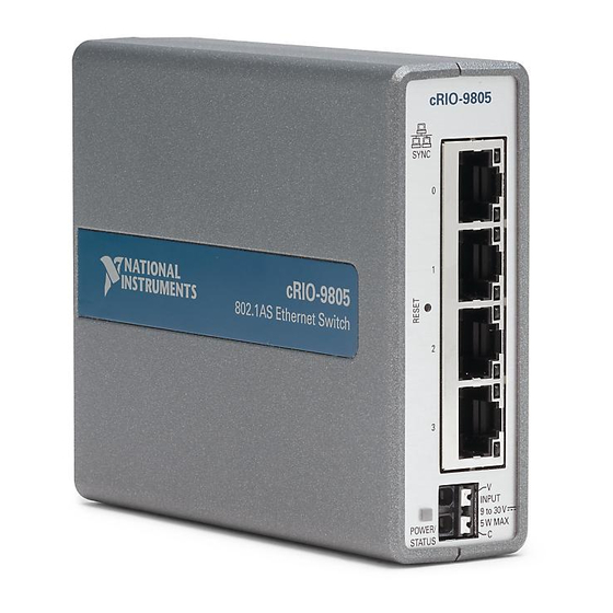
1. Power/Status LED
2. Reset button
3. Ethernet ports 0 to 3
Pinout
V
C
Figure 1. cRIO-9805 Front Panel
cRIO-9805
SYNC
0
1
2
2
3
1
POWER/
STATUS
4. Ethernet LEDs
5. Power connector (9 V to 30 V)
Table 1. Power Connector Pinout
Pin
V
C
3
4
V
INPUT
5
9 to 30 V
5 W MAX
C
Power input
Common
Description
Advertisement
Table of Contents

Subscribe to Our Youtube Channel
Related Manuals for National Instruments cRIO-9805


Summary of Contents for National Instruments cRIO-9805
- Page 1 4-Port 802.1AS Ethernet Switch Expansion Module for CompactRIO This document provides information to help you get started with the cRIO-9805, connecting the module to power, connecting to Ethernet, and configuring the device and the network. Figure 1. cRIO-9805 Front Panel...
- Page 2 LAN link not established Green Solid LAN link established Blinking Activity on LAN 10/100/1000 Yellow Solid 1,000 Mbit/s data rate selected Green Solid 100 Mbit/s data rate selected — 10 Mbit/s data rate selected 2 | ni.com | cRIO-9805 Getting Started Guide...
-
Page 3: Unpacking The Kit
Store the device in the antistatic package when the device is not in use. What You Need to Get Started Kit Contents Verify that the following items are included in the cRIO-9805 kit. 1. cRIO-9805 2. Ethernet cable 3. Safety, Environmental, and Regulatory Information document Required Components •... - Page 4 Expansion Module for CompactRIO User Manual on ni.com/manuals. You can also use the cRIO-9805 with a variety of hardware systems and configurations. For more information about using the module with non-CompactRIO systems, contact NI.
- Page 5 Verify the Power/Status LED is on. Connecting the cRIO-9805 to the Controller Power Connector The cRIO-9805 requires a 9 V to 30 V power supply. You can power both the module and a CompactRIO or CompactDAQ controller from the same power supply. What to Use •...
- Page 6 2.2 lb · in) of torque. Connect a ferrule to the other end of the power wires. Push the ferruled wires directly into the power connector terminals on the cRIO-9805. Power on the power supply. 10. Verify the cRIO-9805 Power/Status LED is on.
- Page 7 • Ethernet cable, included in shipping kit What to Do Complete the following steps to connect the cRIO-9805 to a network. Figure 4. Connecting the cRIO-9805 to a Controller - 9 8 Figure 5. Connecting the cRIO-9805 to a Host Computer - 9 8 cRIO-9805 Getting Started Guide | ©...
-
Page 8: Configuring Your System
Creating a Basic Topology The cRIO-9805 is configured to work in this topology out of the box. Most systems should follow this topology. The host communicates directly with each node through the external switch. Figure 6. Basic Topology... - Page 9 In this topology, the host communicates with all nodes through the most effective path. You must configure the network properly before creating redundant links in the network. cRIO-9805 Getting Started Guide | © National Instruments | 9...
-
Page 10: More Options
Note For more advanced network management needs, visit ni.com/r/ netconfig Locating the Security Label The security label on the cRIO-9805 contains the following information necessary for setting up and configuring your system: • Model name • Serial number •... -
Page 11: Resetting The Module
Resetting the Module to Factory Default Configuration If you press the reset button for five seconds or longer, the module reboots into factory default mode, which returns the module user configuration to the factory-set defaults cRIO-9805 Getting Started Guide | © National Instruments | 11... -
Page 12: Worldwide Support And Services
What to Use • Reset tool What to Do Follow these steps to reset the firmware on the cRIO-9805 to default settings. Press the Reset button. Hold it for five seconds. Confirm the Status LED behavior: The LED lights both blue and yellow to indicate the module is resetting. - Page 13 NI trademarks. Other product and company names mentioned herein are trademarks or trade names of their respective companies. For patents covering NI products/technology, refer to the appropriate location: Help»Patents in your software, the file on your media, or the National Instruments Patent Notice at . You can find patents.txt ni.com/patents...
Need help?
Do you have a question about the cRIO-9805 and is the answer not in the manual?
Questions and answers