Table of Contents
Advertisement
S e r v i c e L i t e r a t u r e
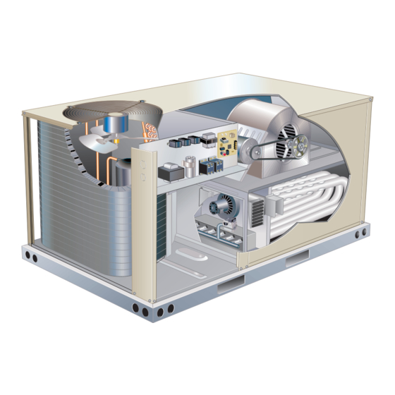
The ZGB packaged gas units are available in standard
cooling efficiency (036S, 048S, 060S, 074S). Cooling ca-
pacities are 3, 4, 5 and 6 tons (10.6 to 20.3kW).
All units are available in single-stage 65,000 BTUH (19
kW), single-stage 108,000 BTUH (32 kW) and two-stage
81/108,000 BTUH (24/32 kW) heat capacities. ZGB048,
060 and 074 units are available in singe-stage 150,000
BTUH (44 kW) and two-stage 113/150,000 BTUH (33/44
KW) heat capacities. Gas heat sections are designed with
aluminized steel tube heat exchangers.
Information contained in this manual is intended for use
by qualified service technicians only. All specifications are
subject to change. Procedures outlined in this manual are
presented as a recommendation only and do not super-
sede or replace local or state codes.
If the unit must be lifted for service, rig unit by attaching
four cables to the holes located in the unit base rail (two
holes at each corner). Refer to the installation instructions
for the proper rigging technique. Stacking brackets can be
removed or left on the unit permanently. If brackets are
removed, any screws removed during installation must be
replaced.
WARNING
Improper installation, adjustment, alteration, service
or maintenance can cause property damage, personal
injury or loss of life. Installation and service must be
performed by a licensed professional HVAC installer or
equivalent, service agency, or the gas supplier.
WARNING
Electric shock hazard. Can cause injury
or death. Before attempting to perform
any service or maintenance, turn the
electrical power to unit OFF at disconnect
switch(es). Unit may have multiple power
supplies.
CAUTION
As with any mechanical equipment, contact with
sharp sheet metal edges can result in personal
injury. Take care while handling this equipment and
wear gloves and protective clothing.
UNIT INFORMATION
UNIT INFORMATION
Corp1807-L2
Revised 09/2021
ZGB036, 048, 060, 074
Page 1
WARNING
To prevent serious injury or death:
1- Lock-out/tag-out before performing maintenance.
2- If system power is required (e.g., smoke detector
maintenance), disable power to blower, remove
fan belt where applicable, and ensure all
controllers and thermostats are set to the "OFF"
position before performing maintenance.
3- Always keep hands, hair, clothing, jewelry, tools,
etc., away from moving parts.
Table of Contents
Options / Accessories . . . . . . . . . . . . . . . . . . . . . Page 2
Specifications. . . . . . . . . . . . . . . . . . . . . . . . . . . . . . . . Page 4
Spec. Gas Heat High Altitude. . . . . . . . . . . . . . . . . . . Page 7
Blower Data . . . . . . . . . . . . . . .. . . . . . . . . . . . . . . . . . .Page 7
Electrical Data . . . . . . . . . . . .. . . . . . . . . . . . . . . . . .Page 21
I Unit Components. . . . . . . . . . .. . . . . . . . . . . . . . . . .Page 25
II Placement and Installation . . . . .. . . . . . . . . . . . . .Page 35
III Start-Up and Installation . . . . . . . . . . .. . . . . . . . .Page 35
IV Charging. . . . . . .. . . . . . . . . . . . . . . . .. . . . . . . . . .Page 37
V System Service Checks. . . . . . . . . . . .. . . . . . .Page 41
VI Maintenance. .. . . . . . . . .. . . . . . . . .. . . . . . . . .. Page 43
VII Accessories . . . .. . . . . . . . .. . . . . . .. . . . . . . . .. Page 45
VIII Diagrams . .. . . . ... . . . . . .. . . . ... . . . . . .. . . . .Page 51
ZGB SERIES
3, 4, 5 and 6 Ton
10.6 to 20.3 kW
Advertisement
Table of Contents


Need help?
Do you have a question about the ZGB Series and is the answer not in the manual?
Questions and answers