Autonics ARIO-C-EI User Manual
Hide thumbs
Also See for ARIO-C-EI:
- Manual (27 pages) ,
- Product manual (4 pages) ,
- Product manual (12 pages)
Table of Contents
Advertisement
Quick Links
Advertisement
Table of Contents

Related Manuals for Autonics ARIO-C-EI


Summary of Contents for Autonics ARIO-C-EI
- Page 1 ARIO-C-EI EtherNet/IP User Manual MTO-ARIOCEIU1-V2.0-2200US...
-
Page 3: Table Of Contents
2. Overview of the ARIO-C-EI........ - Page 4 5.5. Assembly Class (0x04) .............. ...
- Page 5 10.1. Ethernet ................ ...
-
Page 7: Preface
Preface Thank you for purchasing Autonics products. Be sure to read and follow the Safety Precautions thoroughly before use. This manual contains information about the product and how to use it properly, so keep it in a place where users can easily find it. - Page 8 8 Autonics | ARIO-C-EI...
-
Page 9: Manual Guide
• Any or all of the manual may not be edited or copied without permission. • The manual is not provided with the product. • Download and use from our website (www.autonics.com). • The contents of the manual are subject to change without prior notice according to the improvement of the product’s performance, and upgrade notices are provided through our website. - Page 10 10 Autonics | ARIO-C-EI...
-
Page 11: Common Symbols In The Manual
Common Symbols in the Manual Failure to follow instructions may result in serious injury or death. Failure to follow instructions may result in injury or product damage. Supplementary explanation of the function Example of that function Important information about the feature Common Symbols in the Manual ... - Page 12 12 Autonics | ARIO-C-EI...
-
Page 13: Safety Considerations
Safety Considerations Observe all 'Safety Considerations' for safe and proper operation to avoid hazards. Warning 1. Fail-safe device must be installed when using the unit with machinery that may cause serious injury or substantial economic loss. (e.g., nuclear power control, medical equipment, ships, vehicles, railways, aircraft, combustion apparatus, safety equipment, crime/disaster prevention devices, etc.) Failure to follow this instruction may result in personal injury, fire or economic loss. - Page 14 The specifications and dimensions of this manual are subject to change without any notice for product improvement. Be sure to read and follow the considerations written in the instruction manual, other manuals, and technical information on our Autonics website. 14 Autonics | ARIO-C-EI...
-
Page 15: Reference Manuals
Be sure to read the reference manuals below to use the product correctly and follow the precautions written in these manuals. You can download the reference manuals on our Autonics website. Installation manual It contains information for you to setup and install the ARIO Unit. - Page 16 3. Software information: process images, and mapping information, etc. Module manual It contains information on the modules provided by Autonics. 1. Hardware information: specifications, indicators, connection diagram, and dimensions, etc. DAQMaster user manual It contains information and usage guides on ARIO-related functions supported by DAQMaster, the comprehensive device management program.
-
Page 17: Overview Of The Ario-C-Ei
The ARIO-C-EI supports the EtherNet/IP protocol. This coupler composes the physical structure of connected modules and devices and creates input and output process images linked with the data of EtherNet/IP. -
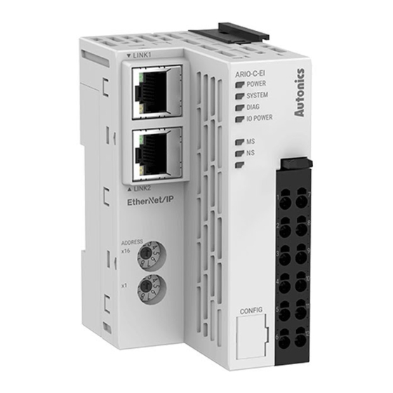
Page 18: Unit Descriptions
(or adapter) in the EtherNet/IP communication network. You can also set the IP address in the DAQMaster. For detailed information on addressing method, refer to the 2.4, “Assign the IP Address”. 18 Autonics | ARIO-C-EI... - Page 19 3. CONFIG Port It is a port to connect to the PC where DAQMaster is installed. 1. Port type: USB Type-B Micro 4. Indicators It displays the status of the coupler and communication connection as shown below. For detailed information on the indicators, refer to the Indicators.
-
Page 20: Ethernet/Ip Communication Connector
For more information on the pin assignment, refer to the table below. Pin no. Color of conductor based on T568A Signal Description Green/White TD + Transmit Data + Green TD - Transmit Data - Orange/White RD + Receive Data + Orange RD - Receive Data - 20 Autonics | ARIO-C-EI... -
Page 21: Assign The Ip Address
2.4. Assign the IP Address • It is recommended to designate the IP address of the coupler the same as the value of the rotary switches. • The IP address cannot be applied while the coupler is operating. • Be sure to start the coupler again to apply the changed IP address. •... -
Page 22: Assign The Ip Address In The Daqmaster
2. To designate the IP address in the DAQMaster, go to the Comm Mode » Property tab of the coupler » Coupler IP(Node Address) and press the Enter key. 3. Reset the ARIO unit in the DAQMaster. 4. The IP address assigned by the DAQMaster is applied. 22 Autonics | ARIO-C-EI... -
Page 23: Connections Of The Power Terminal
2.5. Connections of the Power Terminal Terminal no. Name Description 1, 7 System Power (24 V Power supply for the coupler, module and ABUS to be operated. • The terminals feed the power supply to the 2, 8 System Power (0 V top input contacts. - Page 24 24 Autonics | ARIO-C-EI...
-
Page 25: Indicators
3. Indicators The indicators of the ARIO-C-EI coupler consist of elements indicating the operating status for the coupler, connection status for the field network (EtherNet/IP), and Ethernet as shown in the figure below. For detailed information on each indicator, refer to the following tables below. -
Page 26: Leds For The Coupler Status
The models of the replaced module and the previous one mismatch (normal operation) Flashing (2 times) No module connection (non-recoverable) Flashing (3 times) Abnormal module operation (non-recoverable) Flashing (4 times) The number of modules and data size exceeded Normal operation 26 Autonics | ARIO-C-EI... - Page 27 4. The status of power supply for the module Indicator LED color Status Description IO POWER Green I/O supply voltage of the module: Normal I/O supply voltage of the module: None 3.1. LEDs for the Coupler Status 27...
-
Page 28: Leds For The Field Network Status
LINK 1, 2 Green Link: The device is linked to the Ethernet. The device has no link to the Ethernet. Orange Flashing Activity: The device sends/receives Ethernet frames. The device does not send/receive Ethernet frames. 28 Autonics | ARIO-C-EI... - Page 29 Refer to the timing chart below for the flashing operation of indicators. The operation is repeated as flashing every 200 microseconds and standby for 1 second. 3.3. LEDs for the Ethernet Status 29...
- Page 30 30 Autonics | ARIO-C-EI...
-
Page 31: Process Images
4. Process Images 4.1. Memory Map The ARIO unit composes the memory map in its memory space to assign and manage the data collected by the coupler and modules. The master in the field network controls the input and output devices via this memory map generated by the ARIO unit. -
Page 32: Data Processing In The Modules
4 channels/module (4-CH/module) 1-byte 8 channels/module (8-CH/module) 1-byte 16 channels/module (16-CH/module) 2-byte (= 1-word) Analog input/output 8-bit/channel (8-bit/CH) 1-byte : Byte-oriented 12-bit/channel (12-bit/CH) 2-byte (= 1-word) 16-bit/CH (16-bit/CH) 2-byte (= 1-word) 24-bit/channel (24-bit/CH) 4-byte (= 2-word) 32 Autonics | ARIO-C-EI... -
Page 33: Check The Data Of The Modules
4.2.1. Check the Data of the Modules You can check the data of modules connected with the coupler as shown in the figure below. To check the data, go to Comm Mode » » I/O Monitor in the DAQMaster. The binary, decimal, and hexadecimal are supported as the display format in the DAQMaster. 1. -
Page 34: Example Of The Process Image
The first position of the input process image contains diagnostic information of the coupler with a size of 16 bits (1 word). DAQMaster: An arrangement example of the ARIO unit DAQMaster: The address map of the ARIO unit 34 Autonics | ARIO-C-EI... -
Page 35: Input Process Image
4.3.1. Input Process Image Byte Bit 7 Bit 6 Bit 5 Bit 4 Bit 3 Bit 2 Bit 1 Bit 0 0: Coupler Diagnostic Data High Byte Diagnostic data Low Byte 2: DI04P Ch.4 Ch.3 Ch.2 Ch.1 3: AI02V1 Ch.1 High Byte Ch.1 Low Byte Ch.2 High Byte Ch.2 Low Byte... -
Page 36: Mapping Of The Coupler Diagnostic Data
Checking the connected module 0: Normal state (one or more modules connected) 1: No module connected WP (Warranty Period) Notice of product warranty period (≤ 3 years, 157,680 0: Within the warranty period 1: End of warranty period 36 Autonics | ARIO-C-EI... - Page 37 MS (Module State) The status of connected modules (running with DIAG indicator) 0: Normal state 1: Error CS (Coupler State) The information on the coupler state (running with SYSTEM indicator) 0: Normal state 1: Error • Cause 1: Error occurred in the coupler initialization and settings, etc.
- Page 38 38 Autonics | ARIO-C-EI...
-
Page 39: Object Models
5. Object Models In the EtherNet/IP network, the method and procedures of data exchange among the nodes are designed via multiple object groups. An object is a collection of abstract representations of a specific component in an EtherNet/IP device, including their class and instances together with services and functions. -
Page 40: Supported Object Classes
Data Unit USINT (Unsigned Short Integer) 8-bit 1-byte UINT (Unsigned Integer) 16-bit 1-word UDINT (Unsigned Double Integer) 32-bit 2-word BOOL (Boolean) True (1) / False (0) 8-bit STRUCT (Structure of … ARRAY (Array of … 40 Autonics | ARIO-C-EI... -
Page 41: Identity Class (0X01)
5.3. Identity Class (0x01) It provides the product information about Vendor ID and Device Type to identify the slave device. 5.3.1. Services Service Code Service Name Description 0x0E Get_Attribute_Single It returns the value of a specific attribute. 0x10 Set_Attribute_Single It modifies the value of a specific attribute. 0x05 Reset It executes the service to reset the device. - Page 42 F/W Revision info.: Ver 1.2 (Major = 1, Minor = 2) Major USINT Minor USINT Status WORD The current status of the device Serial UDINT Serial number of the device Number Product SHORT_ Product name: ARIO_C_EI Name STRING 42 Autonics | ARIO-C-EI...
-
Page 43: Message Router Class (0X02)
5.4. Message Router Class (0x02) It transfers the explicit messages to another object. The services and instance attributes are not supported. 5.4. Message Router Class (0x02) 43... -
Page 44: Assembly Class (0X04)
Access Rule Name Data Type Description Vendor ID UINT Number of Vender ID Member List UINT Data Array of Reference for input/output process image Octet Size UINT The byte size of attribute 3 (process image) 44 Autonics | ARIO-C-EI... -
Page 45: Connection Manager Class (0X06)
5.6. Connection Manager Class (0x06) The Connection Manager Class allocates and manages internal resources related to the I/O connections and explicit message connections. A Connection instance or Connection object is created by the Connection Manager class. The Connection parameter is generated by the Forward_Open service. -
Page 46: Quality Of Service Class (0X48)
• Instance 0 (class attribute) Attribute ID Access Rule Name Data Type Description Revision UINT Revision of the QoS Object Default: 1 (0x0001) UINT The maximum instance number Instance of the QoS Object Default: 1 (0x0001) 46 Autonics | ARIO-C-EI... - Page 47 • Instance 1 Attribute ID Access Rule Name Data Type Description DSCP PTP USINT DSCP value for implicit messages Urgent (Priority: Urgent) Default: 55 (Binary 0011 0111) DSCP PTP USINT DSCP value for implicit messages Scheduled (Priority: Scheduled) Default: 47 (Binary 0010 1111) DSCP PTP USINT DSCP value for implicit messages...
-
Page 48: Tcp/Ip Interface Class (0Xf5)
• Instance 0 (class attribute) Attribute ID Access Rule Name Data Type Description Revision UINT Revision of the TCP/IP Interface Object Default: 4 (0x0004) UINT The maximum instance number Instance of the TCP/IP Interface Object Default: 1 (0x0001) 48 Autonics | ARIO-C-EI... - Page 49 • Instance 1 Attribute ID Access Rule Name Data Type Description Status DWORD Interface status Config. DWORD Interface flags that describe configurable Capability items Default: 0x00000015 Config. DWORD Interface control flags Control Physical STRUCT of: Configuration of Physical Link Object Link Object Path size UINT...
-
Page 50: Ethernet Link Class (0Xf6)
Revision of the Ethernet Link Object Default: 4 (0x0004) UINT The maximum instance number Instance of the Ethernet Link Object Default: 2 (0x0002) Number of UINT The number of instances Instances created in the Ethernet Link class Default: 2 (0x0002) 50 Autonics | ARIO-C-EI... - Page 51 • Instance 1, 2 Attribute ID Access Rule Name Data Type Description Interface UDINT Baud rate Speed Default: 100 (0x64) Interface DWORD Interface configuration and status Flags information Bit 0: Link status Bit 1 : Half/full Duplex Bit 2 4: Detection status …...
- Page 52 10 Mbit/s HD : 0x0A 0x00 0x00 10 Mbit/s FD : 0x0A 0x00 0x01 100 Mbit/s HD : 0x64 0x00 0x00 100 Mbit/s FD: 0x64 0x00 0x01 (default) UINT Interface speed USINT Interface Duplex mode 52 Autonics | ARIO-C-EI...
-
Page 53: Studio 5000 Guide
6. Studio 5000 Guide • Be sure to see the version compatibility table of the ARIO Series on our Autonics website to check the software/firmware(SW) and hardware(HW) versions of the coupler and modules. • Refer to the 7.2, “Update the Firmware Version”... - Page 54 • The setting of hexadecimal rotary switches: 0x06 (The last octet of IP address) This chapter only describes based on the Allen-Bradley’s master (PLC) and software. For detailed information on communication connection and usage method with the master, refer to the user manuals provided by the specific manufacturer. 54 Autonics | ARIO-C-EI...
-
Page 55: Create A Ab Plc Project
6.2. Create a AB PLC Project 1. Launch the Studio 5000 and click the New Project 2. Select the connected controller model on the Logix Project Types and designate a project name. Click the Next 6.2. Create a AB PLC Project 55... - Page 56 3. Select the same Revision with the version of Studio 5000 and click the Finish 56 Autonics | ARIO-C-EI...
-
Page 57: Install The Eds File
You can install and manage EDS files on your project planning software. 1. Download the EDS file of the ARIO-C-EI on our Autonics website. 2. Refer to the README.txt in the downloaded folder and select the EDS file suitable for the S/W version of the coupler. - Page 58 5. The EDS installation wizard will be launched. Click the Next 6. Select the Register an EDS file(s) and click the Next 58 Autonics | ARIO-C-EI...
- Page 59 7. Click the to specify the path of the EDS file and click the Browse Next 8. Click the Next 6.3. Install the EDS File 59...
- Page 60 9. Click the Next 10. Click the . The installation of EDS file is completed. Finish 60 Autonics | ARIO-C-EI...
-
Page 61: Add The Ario Unit
6.4. Add the ARIO Unit Be sure to set the controller state to the Offline mode for integrating the modules. 1. Right-click on the Controller Organizer » I/O Configuration » Ethernet and select the New Module. 6.4. Add the ARIO Unit 61... - Page 62 2. Enter the ARIO and select the ARIO-C-EI from the search results. Click the Create 3. Assign a module name and IP address. When assigning an IP address, enter the value of the rotary switches to the last octet of the IP address.
- Page 63 How to set the IP address and communication path ◦ Be sure to set the IP addresses of the master and coupler to be the same up to the network portion of the subnet mask. ◦ Refer to the table below for the range of IP address range depending on the rotary switches settings of the coupler.
- Page 64 4. Connection Fault Indication - An existence of fault is indicated on the controller (PLC), but the communication can be established even though the keying attributes of the coupler and EDS file do not exactly match. 01) Attributes - Vendor, Device Type, Product Code, Major Revision, Minor Revision 64 Autonics | ARIO-C-EI...
- Page 65 5. Click the in the pop-up window. 6. Click the in the New Module window to complete the configuration of ARIO unit. 6.4. Add the ARIO Unit 65...
- Page 66 7. The ARIO module will be created in the Controller Organizer » I/O Configuration » Ethernet. 66 Autonics | ARIO-C-EI...
-
Page 67: Controller Tags
6.5. Controller Tags The controller tags defined in the ARIO-C-EI are created when you install the EDS file in your project. With this EDS file, you can set and monitor the input/output process data on the controller tags tab. Structure of the instance 1. - Page 68 (= 2 bytes) in each channel. Check the number of index from the Module Name:I/O.Data[Index]. • [Example] ARIO_Unit:I.Data[0 to 1] - Channel 1 of the module which is arranged at the first slot in the input process image 68 Autonics | ARIO-C-EI...
-
Page 69: Read The Input Data
6.6. Read the Input Data Expand the Module Name:I to check the data of the connected input modules. The input process image is represented as shown in the figure below in the Studio 5000. 6.6. Read the Input Data 69... -
Page 70: Example Usage
2. Firstly, check the state of a communication connection between the Master and ARIO unit through the Value of Module Name: I.ConnectionFaulted. Expand the Module Name:I.Data[0] to check whether the Value of Module Name:I.Data[0].0 to 3 is 1. (Binary 0000 1111 = 15 70 Autonics | ARIO-C-EI... -
Page 71: Write The Output Data
6.7. Write the Output Data Expand the Module Name:O to check the arrangement of the connected output modules. The output process image is represented as shown in the figure below in the Studio 5000. 6.7. Write the Output Data 71... -
Page 72: Example Usage
1. Expand the Module Name:O.Data[0] and enter 1 to the Value of Module Name:O.Data[0].0 to 3. (Binary 0000 1111 = 15 2. The green LEDs light up on channel 1 to 4 indicators of the modules. 72 Autonics | ARIO-C-EI... - Page 73 Ladder example The figure below shows the following operation - • Input signals are received to channel 1 to 4 of the digital input module. • Send the output signals to channel 1 to 4 of the digital output module. •...
-
Page 74: Download The Program
6.8. Download the Program 1. Click the Offline and select the Download. 2. Select the in the pop-up window. Download 74 Autonics | ARIO-C-EI... -
Page 75: Daqmaster
7.1. Monitor the ARIO Unit 1. Connect the CONFIG port of the ARIO coupler to the PC where the DAQMaster is installed. 2. Select the Supported Device List » AUTONICS » ARIO Config to add the ARIO coupler and then select the Connect »... - Page 76 ARIO Config, the tag list of the connected input/output module is displayed. Double-click the tag to be monitored to add it on the DAQ List window. 4. The tags are added on the DAQ List window as shown below. 76 Autonics | ARIO-C-EI...
- Page 77 5. Double-click the RunTime Screen » Data » (e.g.) Multi Panel to configure the visualized monitoring screen. A multi-panel window will be created on the DAQ Space window. 6. Drag and drop the tags added on the DAQ List window to the Multi Panel window. 7.1.
- Page 78 7. When selecting the Project » Run, you can monitor the channel status of the module. 78 Autonics | ARIO-C-EI...
-
Page 79: Update The Firmware Version
1. Select the to perform the update. Firmware update Without Internet connection 1. Download the latest firmware version of the coupler from the Autonics website. 2. Select the to import the downloaded .zip file. Load firmware file 3. Select the latest version of ARIO-C-EI at the Firmware version list 4. - Page 80 80 Autonics | ARIO-C-EI...
-
Page 81: Dimensions
8. Dimensions • For the detailed drawings, follow the Autonics website. • Unit: mm Coupler 8. Dimensions 81... - Page 82 End module 82 Autonics | ARIO-C-EI...
-
Page 83: Specifications
9. Specifications 9.1. Electrical/Mechanical Specifications Max. number of ≤ 64 (The length of connected modules: ≤ 768 mm) connectable modules Memory size • Input: 504-byte • Output: 504-byte Power supply • Unit (coupler + module): ≤ 9.6 W, ≤ 400 mA (≤ 200 mA/CH, 2-CH/COM) •... -
Page 84: Environmental Conditions
Ambient temperature -10 to 55 ℃, storage: -25 to 70 ℃ (no freezing or condensation) Ambient humidity 35 to 85 %RH, storage: 35 to 85 %RH (no freezing or condensation) Protection rating IP20 (IEC standard) 84 Autonics | ARIO-C-EI... -
Page 85: Communication Interface
Address settings Hexadecimal rotary switches, DAQMaster Topology Bus, Line, Star EDS file Download the EDS file on our Autonics website 01) The transmission rate is determined after performing Auto-negotiation depending on the network quality. 10.2. ABUS Transmission rate 4 Mbps... - Page 86 Dimensions or specifications on this manual are subject to change and some models may be discontinued without notice. www.autonics.com...
Need help?
Do you have a question about the ARIO-C-EI and is the answer not in the manual?
Questions and answers