Table of Contents
Advertisement
Quick Links
Advertisement
Table of Contents

Related Manuals for Autonics ARIO-C-DN


Summary of Contents for Autonics ARIO-C-DN
- Page 1 ARIO-C-DN DeviceNet User Manual MTO-ARIOCDNU1-V2.0-2200US...
-
Page 3: Table Of Contents
2. Overview of ARIO-C-DN ........ - Page 4 5.5. DeviceNet Class (0x03) .............. ...
-
Page 5: Preface
Preface Thank you for purchasing Autonics products. Be sure to read and follow the Safety Precautions thoroughly before use. This manual contains information about the product and how to use it properly, so keep it in a place where users can easily find it. - Page 6 6 Autonics | ARIO-C-DN...
-
Page 7: Manual Guide
• Any or all of the manual may not be edited or copied without permission. • The manual is not provided with the product. • Download and use from our website (www.autonics.com). • The contents of the manual are subject to change without prior notice according to the improvement of the product’s performance, and upgrade notices are provided through our website. - Page 8 8 Autonics | ARIO-C-DN...
-
Page 9: Common Symbols In The Manual
Common Symbols in the Manual Failure to follow instructions may result in serious injury or death. Failure to follow instructions may result in injury or product damage. Supplementary explanation of the function Example of that function Important information about the feature Common Symbols in the Manual ... - Page 10 10 Autonics | ARIO-C-DN...
-
Page 11: Safety Considerations
Safety Considerations Observe all 'Safety Considerations' for safe and proper operation to avoid hazards. Warning 1. Fail-safe device must be installed when using the unit with machinery that may cause serious injury or substantial economic loss. (e.g., nuclear power control, medical equipment, ships, vehicles, railways, aircraft, combustion apparatus, safety equipment, crime/disaster prevention devices, etc.) Failure to follow this instruction may result in personal injury, fire or economic loss. - Page 12 The specifications and dimensions of this manual are subject to change without any notice for product improvement. Be sure to read and follow the considerations written in the instruction manual, other manuals, and technical information on our Autonics website. 12 Autonics | ARIO-C-DN...
-
Page 13: Reference Manuals
Be sure to read the reference manuals below to use the product correctly and follow the precautions written in these manuals. You can download the reference manuals on our Autonics website. Installation manual It contains information for you to setup and install the ARIO Unit. - Page 14 3. Software information: process images, and mapping information, etc. Module manual It contains information on the modules provided by Autonics. 1. Hardware information: specifications, indicators, connection diagram, and dimensions, etc. DAQMaster user manual It contains information and usage guides on ARIO-related functions supported by DAQMaster, the comprehensive device management program.
-
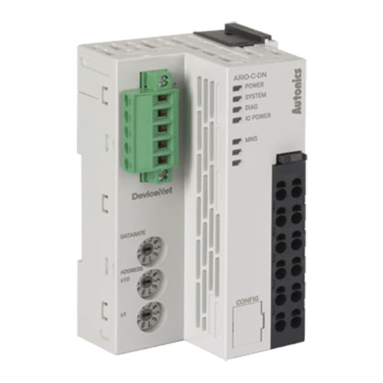
Page 15: Overview Of Ario-C-Dn
The ARIO-C-DN supports the DeviceNet protocol. This coupler composes the physical structure of connected modules and devices and creates input and output process images linked with the data of DeviceNet. -
Page 16: Unit Descriptions
(MAC-ID) of the coupler in the DeviceNet communication network. You can also set the node address in the DAQMaster. For detailed information on addressing method, refer to the 2.5, “Assign the Node Address (MAC- ID)”. 16 Autonics | ARIO-C-DN... - Page 17 4. CONFIG Port It is a port to connect to the PC where DAQMaster is installed. 1. Port type: USB Type-B Micro 5. Indicators It displays the status of the coupler and communication connection as shown below. For detailed information on the indicators, refer to the Indicators.
-
Page 18: Devicenet Communication Connector
Pin no. Marking on the connector Color Description +24 V DeviceNet power input H: CAN_H White CAN High signal SH: Shield Shield L: CAN_L Blue CAN Low signal Black Signal ground (-24 V , 0 V 18 Autonics | ARIO-C-DN... -
Page 19: Set The Baud Rate
2.4. Set the Baud Rate • Be sure to use the connector and cable approved by the Open DeviceNet Vendors Association (ODVA). • Be sure not to exceed the maximum cable length of each baud rate. Refer to the table below for you to set the baud rate of DeviceNet via the DATARATE rotary switch. The selected baud rate should be the same as the type of DeviceNet Master. -
Page 20: Assign The Node Address (Mac-Id)
2. To designate the node address in the DAQMaster, go to the Comm Mode » Property tab of the coupler » Node Address and press the Enter key. 3. Reset the ARIO unit in the DAQMaster. 4. The node address assigned by the DAQMaster is applied. 20 Autonics | ARIO-C-DN... -
Page 21: Connections Of The Power Terminal
2.6. Connections of the Power Terminal Terminal no. Name Description 1, 7 System Power (24 V Power supply for the coupler, module and ABUS to be operated. • The terminals feed the power supply to the 2, 8 System Power (0 V top input contacts. - Page 22 22 Autonics | ARIO-C-DN...
-
Page 23: Indicators
3. Indicators The indicators of the ARIO-C-DN coupler consist of elements indicating the operating status for the coupler and connection status for the field network (DeviceNet) as shown in the figure below. For detailed information on each indicator, refer to the following tables below. -
Page 24: Leds For The Coupler Status
The models of the replaced module and the previous one mismatch (normal operation) Flashing (2 times) No module connection (non-recoverable) Flashing (3 times) Abnormal module operation (non-recoverable) Flashing (4 times) The number of modules and data size exceeded Normal operation 24 Autonics | ARIO-C-DN... - Page 25 4. The status of power supply for the module Indicator LED color Status Description IO POWER Green I/O supply voltage of the module: Normal I/O supply voltage of the module: None 3.1. LEDs for the Coupler Status 25...
-
Page 26: Leds For The Field Network Status
• MAC address validation (Dup_MAC_ID test) not yet completed Green/Red • Device supply voltage: None • Network supply voltage: None • MAC address validation (Dup_MAC_ID test) not yet completed Flashing Self-test: The device is performing its power up testing. 26 Autonics | ARIO-C-DN... - Page 27 Refer to the timing chart below for the flashing operation of indicators. The operation is repeated as flashing every 200 microseconds and standby for 1 second. 3.2. LEDs for the Field Network Status 27...
- Page 28 28 Autonics | ARIO-C-DN...
-
Page 29: Process Images
4. Process Images 4.1. Memory Map The ARIO unit composes the memory map in its memory space to assign and manage the data collected by the coupler and modules. The master in the field network controls the input and output devices via this memory map generated by the ARIO unit. -
Page 30: Data Processing In The Modules
4 channels/module (4-CH/module) 1-byte 8 channels/module (8-CH/module) 1-byte 16 channels/module (16-CH/module) 2-byte (= 1-word) Analog input/output 8-bit/channel (8-bit/CH) 1-byte : Byte-oriented 12-bit/channel (12-bit/CH) 2-byte (= 1-word) 16-bit/CH (16-bit/CH) 2-byte (= 1-word) 24-bit/channel (24-bit/CH) 4-byte (= 2-word) 30 Autonics | ARIO-C-DN... -
Page 31: Check The Data Of The Modules
4.2.1. Check the Data of the Modules You can check the data of modules connected with the coupler as shown in the figure below. To check the data, go to Comm Mode » » I/O Monitor in the DAQMaster. The binary, decimal, and hexadecimal are supported as the display format in the DAQMaster. 1. -
Page 32: Example Of The Process Image
The first position of the input process image contains diagnostic information of the coupler with a size of 16 bits (1 word). DAQMaster: An arrangement example of the ARIO unit DAQMaster: The address map of the ARIO unit 32 Autonics | ARIO-C-DN... -
Page 33: Input Process Image
4.3.1. Input Process Image Byte Bit 7 Bit 6 Bit 5 Bit 4 Bit 3 Bit 2 Bit 1 Bit 0 0: Coupler Diagnostic Data High Byte Diagnostic data Low Byte 2: DI04P Ch.4 Ch.3 Ch.2 Ch.1 3: AI02V1 Ch.1 High Byte Ch.1 Low Byte Ch.2 High Byte Ch.2 Low Byte... -
Page 34: Mapping Of The Coupler Diagnostic Data
Checking the connected module 0: Normal state (one or more modules connected) 1: No module connected WP (Warranty Period) Notice of product warranty period (≤ 3 years, 157,680 0: Within the warranty period 1: End of warranty period 34 Autonics | ARIO-C-DN... - Page 35 MS (Module State) The status of connected modules (running with DIAG indicator) 0: Normal state 1: Error CS (Coupler State) The information on the coupler state (running with SYSTEM indicator) 0: Normal state 1: Error • Cause 1: Error occurred in the coupler initialization and settings, etc.
- Page 36 36 Autonics | ARIO-C-DN...
-
Page 37: Object Models
5. Object Models In the DeviceNet network, the method and procedures of data exchange among the nodes are designed via multiple object groups. An object is a collection of abstract representations of a specific component in an DeviceNet device, including their class and instances together with services and functions. -
Page 38: Supported Object Classes
Data Size Data Unit USINT (Unsigned Short Integer) 8-bit 1-byte UINT (Unsigned Integer) 16-bit 1-word UDINT (Unsigned Double Integer) 32-bit 2-word BOOL (Boolean) True (1) / False (0) 8-bit STRUCT (Structure of…) ARRAY (Array of…) 38 Autonics | ARIO-C-DN... -
Page 39: Identity Class (0X01)
5.3. Identity Class (0x01) It provides the product information about Vendor ID and Device Type to identify the slave device. 5.3.1. Services Service Code Service Name Description 0x01 Get_Attribute_All It returns the attribute value of an instance or class. 0x0E Get_Attribute_Single It returns the value of a specific attribute. -
Page 40: Message Router Class (0X02)
5.4. Message Router Class (0x02) It transfers the explicit messages to another object. The services and instance attributes are not supported. 40 Autonics | ARIO-C-DN... -
Page 41: Devicenet Class (0X03)
5.5. DeviceNet Class (0x03) It contains the information for DeviceNet network configuration such as MAC ID and baud rates, etc. 5.5.1. Services Service Code Service Name Description 0x0E Get_Attribute_Single It returns the value of a specific attribute. 0x10 Set_Attribute_Single It modifies the value of a specific attribute. 5.5.2. -
Page 42: Connection Class (0X05)
Change of State (COS), COS: Data is exchanged with the master when a state of Cyclic I/O connection slave is changed. Cyclic: The slave sends the data to the master every selected cycle time. 42 Autonics | ARIO-C-DN... -
Page 43: Instance Attributes
5.6.3. Instance Attributes Instance 1, 2, 3, 4 Attribute ID Access Rule Name Data Type Description Connection USINT Status of the object State Connection USINT Explicit messages or I/O connection Type Transport USINT Definition of the connection behaviors Type Produced UINT Produced connection ID assigned to CAN Connection... - Page 44 The byte size of the Consumed Connection Path Path attribute Length Consumed Array of Specifies the Application objects, whose Connection USINT data are received by this connection object Path ID Inhibit Time USINT Definition of the minimum time between data transmission 44 Autonics | ARIO-C-DN...
-
Page 45: Acknowledge Handler Class (0X2B)
5.7. Acknowledge Handler Class (0x2B) Processing the response message of the slave. 5.7.1. Services Service Code Service Name Description 0x0E Get_Attribute_Single It returns the value of a specific attribute. 0x10 Set_Attribute_Single It modifies the value of a specific attribute. 5.7.2. Instance Attributes •... - Page 46 46 Autonics | ARIO-C-DN...
-
Page 47: Cx-Programmer Guide
6. CX-Programmer Guide • Be sure to see the version compatibility table of the ARIO Series on our Autonics website to check the software/firmware(SW) and hardware(HW) versions of the coupler and modules. • Refer to the 7.2, “Update the Firmware Version”... - Page 48 (Set the baud rate same as the type of the DeviceNet master.) This chapter only describes based on the OMRON’s master (PLC) and software. For detailed information on communication connection and usage method with the master, refer to the user manuals provided by the specific manufacturer. 48 Autonics | ARIO-C-DN...
-
Page 49: Create A Omron Plc Project
6.2. Create a OMRON PLC Project 1. Launch the CX-Programmer. 2. Click the (New) button on the toolbar. 3. Configure the connected PLC CPU in the Change PLC window and click the ◦ Device Type: CJ2M, CPU Type: CPU31 ◦ Network Type: USB 4. - Page 50 6. Click the (Program Mode) button on the toolbar. Click the in the pop-up window to change the PLC operating mode to the program mode. 7. Double-click the IO Table and Unit Setup in the project workspace. 50 Autonics | ARIO-C-DN...
- Page 51 8. When expanding the Main Rack in the PLC IO Table window, you can figure out that the DeviceNet Master unit is not added. 9. Click the Options » Create in the top menu. Click the in the pop-up window to proceed with the create IO table and initialize CPU bus settings.
- Page 52 10. Click the in the Transfer from PLC window. Click the in the Transfer Results window. Transfer 11. The DeviceNet master unit is added to the Main Rack. 52 Autonics | ARIO-C-DN...
-
Page 53: Validate The Scan List
6.3. Validate the Scan List 1. Double-click the added DeviceNet Master unit in the PLC IO Table window to open the parameter list window. 2. Set the value of the Scan List Clear Switch parameter to ON and click the Transfer(PC to Unit) Click the in the pop-up window to transfer the parameters to the DeviceNet Master unit. - Page 54 4. The green LED lights up on the SYSTEM and MNS indicators of the ARIO coupler. The green LED lights up on the NS indicator of the CJ1W-DRM21 (the DeviceNet Master unit). 54 Autonics | ARIO-C-DN...
- Page 55 5. Click the Options » Start Special Application » Start with Settings Inherited in the top menu to launch the CX-Integrator. 6.3. Validate the Scan List 55...
-
Page 56: Cx-Integrator Guide
You can install and manage EDS files on your project planning software. 1. Download the EDS file of ARIO-C-DN on our Autonics website. 2. Refer to the README.txt in the downloaded folder and select the EDS file suitable for the S/W version of the coupler. -
Page 57: Configure The Communication
6.4.2. Configure the Communication 1. Click the (Communication Settings) on the toolbar. 2. Configure the connected PLC CPU in the Change PLC window and click the ◦ Device Type: CJ2M, CPU Type: CPU31 3. Set the Network Type for the connected PLC CPU in the Change PLC window and click the ◦... - Page 58 (3) Work Online connect to the PLC. 5. You can see that the Target PLC and DeviceNet Master unit are connected to the Relay PLC in the online information window. 58 Autonics | ARIO-C-DN...
-
Page 59: Add The Ario Unit
6.4.3. Add the ARIO Unit 1. Right-click » Connect on the added DeviceNet Master unit. 2. Click the in the bottom of the pop-up window. Transfer 3. The network configuration is represented as shown below after the scan is completed. 6.4. - Page 60 ◦ Data size of output module (Out Size): 10-byte ◦ Start address of output data (Out Ch): 3206 ◦ Data size of input module (In Size): 10-byte ◦ Start address of input data (In Ch): 3306 60 Autonics | ARIO-C-DN...
-
Page 61: Read The Input Data
6.5. Read the Input Data 1. Double-click the Memory in the project workspace of CX-Programmer. 2. Double-click the CIO in the PLC Memory window. The CIO window is created on the right side of the screen. 6.5. Read the Input Data 61... - Page 62 You can see that the input signals are given to channel 1 to 4 of the first digital input module. CIO3306 Channel Ch. 1 to 8 Ch. 1 to 8 Ch. 4 Ch. 3 Ch. 2 Ch. 1 Input module DI 2 DI 1 AI 3 62 Autonics | ARIO-C-DN...
-
Page 63: Write The Output Data
6.6. Write the Output Data 1. Double-click the Memory in the project workspace of CX-Programmer. 2. Double-click the CIO in the PLC Memory window. The CIO window is created on the right side of the screen. 6.6. Write the Output Data 63... - Page 64 Transfer to PLC on the top menu. Firstly, check the Transfer Range in the pop-up window and then click the . (The green LEDs light up on the 1 to 4 channel indicators Transfer To PLC of the digital output module.) 64 Autonics | ARIO-C-DN...
- Page 65 5. You can see the output channels under the Monitor mode. CIO3206 Channel Ch. 1 to 8 Ch. 1 to 8 Ch. 4 Ch. 3 Ch. 2 Ch. 1 Output module DO 2 DO 1 AO 3 6.6. Write the Output Data 65...
- Page 66 66 Autonics | ARIO-C-DN...
-
Page 67: Daqmaster
7.1. Monitor the ARIO Unit 1. Connect the CONFIG port of the ARIO coupler to the PC where the DAQMaster is installed. 2. Select the Supported Device List » AUTONICS » ARIO Config to add the ARIO coupler and then select the Connect »... - Page 68 ARIO Config, the tag list of the connected input/output module is displayed. Double-click the tag to be monitored to add it on the DAQ List window. 4. The tags are added on the DAQ List window as shown below. 68 Autonics | ARIO-C-DN...
- Page 69 5. Double-click the RunTime Screen » Data » (e.g.) Multi Panel to configure the visualized monitoring screen. A multi-panel window will be created on the DAQ Space window. 6. Drag and drop the tags added on the DAQ List window to the Multi Panel window. 7.1.
- Page 70 7. When selecting the Project » Run, you can monitor the channel status of the module. 70 Autonics | ARIO-C-DN...
-
Page 71: Update The Firmware Version
1. Select the to perform the update. Firmware update Without Internet connection 1. Download the latest firmware version of the coupler from the Autonics website. 2. Select the to import the downloaded .zip file. Load firmware file 3. Select the latest version of ARIO-C-DN at the Firmware version list 4. - Page 72 72 Autonics | ARIO-C-DN...
-
Page 73: Dimensions
8. Dimensions • For the detailed drawings, follow the Autonics website. • Unit: mm Coupler 8. Dimensions 73... - Page 74 End module 74 Autonics | ARIO-C-DN...
-
Page 75: Specifications
9. Specifications 9.1. Electrical/Mechanical Specifications Max. number of ≤ 32 (The length of connected modules: ≤ 384 mm) connectable modules Memory size • Input: 255-byte • Output: 255-byte Power supply • Unit (coupler + module): ≤ 9.6 W, ≤ 400 mA (≤ 200 mA/CH, 2-CH/COM) •... -
Page 76: Environmental Conditions
Ambient temperature -10 to 55 ℃, storage: -25 to 70 ℃ (no freezing or condensation) Ambient humidity 35 to 85 %RH, storage: 35 to 85 %RH (no freezing or condensation) Protection rating IP20 (IEC standard) 76 Autonics | ARIO-C-DN... -
Page 77: Communication Interface
Communication type Poll, Bit-Strobe, Cyclic, COS (Change of State) Number of nodes ≤ 64 Address settings Decimal rotary switches, DAQMaster Topology Trunk, Drop Line, Daisy Chain EDS file Download the EDS file on our Autonics website 10.1. CAN Bus 77... -
Page 78: Abus
10.2. ABUS Transmission rate 4 Mbps Topology Bus, Drop Line 78 Autonics | ARIO-C-DN... - Page 79 Dimensions or specifications on this manual are subject to change and some models may be discontinued without notice. www.autonics.com...
Need help?
Do you have a question about the ARIO-C-DN and is the answer not in the manual?
Questions and answers