Ryobi BD4601, BD4601G - BELT / DISC SANDER Manual
- Repair sheet (5 pages) ,
- Operator's manual (12 pages) ,
- Operator's manual (40 pages)
Advertisement
- 1 GENERAL SAFETY RULES
- 2 SPECIFIC SAFETY RULES
- 3 SYMBOLS
- 4 ELECTRICAL
- 5 FEATURES
-
6
ASSEMBLY
- 6.1 LOOSE PARTS LIST
- 6.2 UNPACKING
- 6.3 INSTALLING SANDING DISC AND DISC GUARD
- 6.4 INSTALLING/REPLACING SANDING BELT
- 6.5 MOUNTING THE WORK TABLE FOR USE WITH THE DISC SANDER
- 6.6 MOUNTING THE WORK TABLE FOR USE WITH THE BELT SANDER
- 6.7 ASSEMBLING WORK SUPPORT
- 6.8 MOUNTING BELT/DISC SANDER TO WORK-BENCH
- 6.9 CLAMPING BELT/DISC SANDER TO WORKBENCH
- 7 OPERATION
- 8 ADJUSTMENTS
- 9 MAINTENANCE
- 10 Documents / Resources
GENERAL SAFETY RULES

To reduce the risk of injury, the user must read and understand the operator's manual before using this product.
Read and understand all instructions. Failure to follow all instructions listed below, may result in electric shock, fire and/or serious personal injury.
READ ALL INSTRUCTIONS
WORK AREA
- KNOW YOUR POWER TOOL. Read the operator's manual carefully. Learn the applications and limitations as well as specific potential hazards related to this tool.
- GUARD AGAINST ELECTRICAL SHOCK BY PREVENTING BODY CONTACT WITH GROUNDED SURFACES. For example: pipes, radiators, ranges, refrigerator enclosures.
- KEEP GUARDS IN PLACE and in working order.
- REMOVE ADJUSTING KEYS AND WRENCHES. Form habit of checking to see keys and adjusting wrenches are removed from tool before turning it on.
- KEEP THE WORK AREA CLEAN. Cluttered work areas and work benches invite accidents. DO NOT leave tools or pieces of wood on the tool while it is in operation.
- DO NOT USE IN DANGEROUS ENVIRONMENTS. Do not use power tools in damp or wet locations or expose them to rain. Keep the work area well lit.
- KEEP CHILDREN AND VISITORS AWAY. All visitors should wear safety glasses and be kept a safe distance from work area. Do not let visitors contact tool or extension cord while operating.
- MAKE WORKSHOP CHILDPROOF with padlocks, master switches, or by removing starter keys.
- DON'T FORCE THE TOOL. It will do the job better and safer at the rate for which it was designed.
- USE THE RIGHT TOOL. Do not force the tool or attachment to do a job for which it was not designed.
- USE THE PROPER EXTENSION CORD. Make sure your extension cord is in good condition. Use only a cord heavy enough to carry the current your product will draw. An undersized cord will cause a drop in line voltage resulting in loss of power and overheating. A wire gauge size (A.W.G.) of at least 16 is recommended for an extension cord 50 feet or less in length. If in doubt, use the next heavier gauge. The smaller the gauge number, the heavier the cord.
- DRESS PROPERLY. Do not wear loose clothing, gloves, neckties, or jewelry. They can get caught and draw you into moving parts. Also wear protective hair covering to contain long hair.
- ALWAYS WEAR SAFETY GLASSES WITH SIDE SHIELDS. Everyday eyeglasses have only impact-resistant lenses, they are NOT safety glasses.
- SECURE WORK. Use clamps or a vise to hold work when practical, it is safer than using your hand and frees both hands to operate the tool.
- DO NOT OVERREACH. Keep proper footing and balance at all times.
- MAINTAIN TOOLS WITH CARE. Keep tools sharp and clean for best and safest performance. Follow instructions for lubricating and changing accessories.
- DISCONNECT TOOLS. When not in use, before servicing, or when changing attachments, blades, bits, cutters, etc., all tools should be disconnected from power source.
- AVOID ACCIDENTAL STARTING. Be sure switch is off when plugging in any tool.
- USE RECOMMENDED ACCESSORIES. Consult the operator's manual for recommended accessories. The use of improper accessories may result in injury.
- NEVER STAND ON TOOL. Serious injury could occur if the tool is tipped.
- CHECK DAMAGED PARTS. Before further use of the tool, a guard or other part that is damaged should be carefully checked to determine that it will operate properly and perform its intended function. Check for alignment of moving parts, binding of moving parts, breakage of parts, mounting and any other conditions that may affect its operation. A guard or other part that is damaged must be properly repaired or replaced by an authorized service center to avoid risk of personal injury.
- USE THE RIGHT DIRECTION OF FEED. Feed work into a blade, cutter, or sanding spindle against the direction of rotation of the blade, cutter, or sanding spindle only.
- NEVER LEAVE TOOL RUNNING UNATTENDED. TURN THE POWER OFF. Don't leave tool until it comes to a complete stop.
- PROTECT YOUR LUNGS. Wear a face or dust mask if the cutting operation is dusty.
- PROTECT YOUR HEARING. Wear hearing protection during extended periods of operation.
- DO NOT ABUSE CORD. Never carry tool by the cord or yank it to disconnect from receptacle. Keep cord from heat, oil, and sharp edges.
- USE OUTDOOR EXTENSION CORDS. When tool is used outdoors, use only extension cords with approved ground connection that are intended for use outdoors and so marked.
- KEEP BLADES CLEAN, SHARP, AND WITH SUFFICIENT SET. Sharp blades minimize stalling and kickback.
- NEVER USE IN AN EXPLOSIVE ATMOSPHERE. Normal sparking of the motor could ignite fumes.
- INSPECT TOOL CORDS PERIODICALLY. If damaged, have repaired by a qualified service technician at an authorized service facility. The conductor with insulation having an outer surface that is green with or without yellow stripes is the equipment-grounding conductor. If repair or replacement of the electric cord or plug is necessary, do not connect the equipment-grounding conductor to a live terminal. Repair or replace a damaged or worn cord immediately. Stay constantly aware of cord location and keep it well away from the rotating blade.
- INSPECT EXTENSION CORDS PERIODICALLY and replace if damaged.
- KEEP TOOL DRY, CLEAN, AND FREE FROM OIL AND GREASE. Always use a clean cloth when cleaning. Never use brake fluids, gasoline, petroleum-based products, or any solvents to clean tool.
- STAY ALERT AND EXERCISE CONTROL. Watch what you are doing and use common sense. Do not operate tool when you are tired. Do not rush.
- DO NOT USE TOOL IF SWITCH DOES NOT TURN IT ON AND OFF. Have defective switches replaced by an authorized service center.
- INSPECT FOR AND REMOVE ALL NAILS FROM LUMBER BEFORE USING THIS TOOL. Following this rule will reduce the risk of serious personal injury.
- NEVER START A TOOL WHEN ANY ROTATING COMPONENT IS IN CONTACT WITH THE WORKPIECE.
- DO NOT OPERATE A TOOL WHILE UNDER THE INFLUENCE OF DRUGS, ALCOHOL, OR ANY MEDICATION.
- WHEN SERVICING use only identical replacement parts. Use of any other parts may create a hazard or cause product damage.
- USE ONLY RECOMMENDED ACCESSORIES listed in this manual or addendums. Use of accessories that are not listed may cause the risk of personal injury. Instructions for safe use of accessories are included with the accessory.
- DOUBLE CHECK ALL SETUPS. Make sure the spindle or sanding belt assembly is tight and not making contact with sander or workpiece before connecting to power supply.
SPECIFIC SAFETY RULES
- FIRMLY CLAMP OR BOLT your tool to a workbench or table at approximately hip height.
- NEVER stand or have any part of your body in line with the path of the workpiece.
- PLAN YOUR WORK TO REDUCE THE RISK OF THROWBACKS (when the workpiece catches the sanding drum and is torn from your hands).
- MAKE SURE THERE'S NO DEBRIS between the workpiece and its supports.
- WHEN SANDING IRREGULARLY SHAPED WORK-PIECES, plan your work support so it will not slip and be pulled from your hands.
- USE EXTRA CAUTION WITH LARGE, very small or awkward workpieces.
- NEVER USE THIS TOOL to finish pieces too small to hold by hand.
- USE EXTRA SUPPORTS (TABLES, SAW HORSES, BLOCKS, ETC.) for any workpieces large enough to tip when not secured to the work surface.
- NEVER sand more than one piece at a time. DO NOT STACK more than one workpiece on the sander table at a time.
- ALWAYS FEED WORKPIECE FROM LEFT TO RIGHT against the direction the drum sleeve is rotating.
- DO NOT USE DRUMS, sanding sleeves or belts which show visual signs of wear such as grooves, tears or rips.
- ALWAYS STAY ALERT! Do not allow familiarity (gained from frequent use of your sander) to cause a careless mistake. ALWAYS REMEMBER that a careless fraction of a second is sufficient to inflict severe injury.
- MAKE SURE THE WORK AREA HAS AMPLE LIGHTING to see the work and that no obstructions will interfere with safe operation BEFORE performing any work using your tool.
- ALWAYS TURN OFF THE SANDER before disconnecting it to avoid accidental starting when reconnecting to power supply. NEVER leave the tool unattended while connected to a power source.
- SUPPORT WORKPIECE with miter gauge, work rest, or worktable.
- MAINTAIN 1/16 in. clearance between worktable and sanding belt or disc.
- AVOID KICKBACK by sanding in accordance with directional arrows.
- IF THE POWER SUPPLY CORD IS DAMAGED, it must be replaced only by the manufacturer or by an authorized service center to avoid risk.
- THIS TOOL should have the following markings:
- Wear eye protection.
- Support workpiece with miter gauge, backstop (work support), or worktable.
- Maintain 1/16 in. maximum clearance between work table and sanding belt or disc.
- Do not perform any operation freehand.
- Avoid kickback by sanding in accordance with directional arrows.
- SAVE THESE INSTRUCTIONS. Refer to them frequently and use them to instruct others who may use this tool. If you loan someone this tool, loan them these instructions also.
SYMBOLS
The following signal words and meanings are intended to explain the levels of risk associated with this product.
| SYMBOL | SIGNAL | MEANING |
 | DANGER: | Indicates a hazardous situation, which, if not avoided, will result in death or serious injury. |
| | WARNING: | Indicates a hazardous situation, which, if not avoided, could result in death or serious injury. |
 | CAUTION: | Indicates a hazardous situation, that, if not avoided, may result in minor or moderate injury. |
 | NOTICE: | (Without Safety Alert Symbol) Indicates information considered important, but not related to a potential injury (e.g. messages relating to property damage). |
Some of the following symbols may be used on this product. Please study them and learn their meaning. Proper interpretation of these symbols will allow you to operate the product better and safer.
| SYMBOL | NAME | DESIGNATION/EXPLANATION |
| | Safety Alert | Indicates a potential personal injury hazard. |
 | Read Operator's Manual | To reduce the risk of injury, user must read and understand operator's manual before using this product. |
 | Eye Protection | Always wear safety goggles or safety glasses with side shields and, as necessary, a full face shield when operating this product. |
 | Wet Conditions Alert | Do not expose to rain or use in damp locations. |
 | No Hands Symbol | Failure to keep your hands away from the blade will result in serious personal injury. |
| V | Volts | Voltage |
| A | Amperes | Current |
| Hz | Hertz | Frequency (cycles per second) |
| min | Minutes | Time |
 | Alternating Current | Type of current |
| no | No Load Speed | Rotational speed, at no load |
| .../min | Per Minute | Revolutions, strokes, surface speed, orbits etc., per minute |
ELECTRICAL
EXTENSION CORDS
Use only 3-wire extension cords that have 3-prong grounding plugs and 3-pole receptacles that accept the tool's plug. When using a power tool at a considerable distance from the power source, use an extension cord heavy enough to carry the current that the tool will draw. An undersized extension cord will cause a drop in line voltage, resulting in a loss of power and causing the motor to overheat. Use the chart provided below to determine the minimum wire size required in an extension cord. Only round jacketed cords listed by Underwriter's Laboratories (UL) should be used.
**Ampere rating (on tool data plate)
| 0-2.0 | 2.1-3.4 | 3.5-5.0 | 5.1-7.0 | 7.1-12.0 | 12.1-16.0 | |
| Cord Length | Wire Size (A.W.G.) | |||||
| 25' | 16 | 16 | 16 | 16 | 14 | 14 |
| 50' | 16 | 16 | 16 | 14 | 14 | 12 |
| 100' | 16 | 16 | 14 | 12 | 10 | — |
**Used on 12 gauge - 20 amp circuit.
NOTE: AWG = American Wire Gauge
When working with the tool outdoors, use an extension cord that is designed for outside use. This is indicated by the letters "W-A" or "W" on the cord's jacket.
Before using an extension cord, inspect it for loose or exposed wires and cut or worn insulation.
- Keep the extension cord clear of the working area. Position the cord so that it will not get caught on lumber, tools or other obstructions while you are working with a power tool. Failure to do so can result in serious personal injury.
- Check extension cords before each use. If damaged replace immediately. Never use tool with a damaged cord since touching the damaged area could cause electrical shock resulting in serious injury.
ELECTRICAL CONNECTION
This tool is powered by a precision-built electric motor. It should be connected to a power supply that is 120 volts, AC only (normal household current), 60 Hz. Do not operate this tool on direct current (DC). A substantial voltage drop will cause a loss of power and the motor will overheat. If the tool does not operate when plugged into an outlet, double check the power supply.
SPEED AND WIRING
The belt speed of this tool is approximately 1,900 SFM. This speed is not constant and decreases under a load or with lower voltage. For voltage, the wiring in a shop is as important as the motor's horsepower rating. A line intended only for lights cannot properly carry a power tool motor. Wire that is heavy enough for a short distance will be too light for a greater distance. A line that can support one power tool may not be able to support two or three tools.
GROUNDING INSTRUCTIONS

- Grounding pin
- 120V grounded outlet
In the event of a malfunction or breakdown, grounding provides a path of least resistance for electric current to reduce the risk of electric shock. This tool is equipped with an electric cord having an equipment-grounding conductor and a grounding plug. The plug must be plugged into a matching outlet that is properly installed and grounded in accordance with all local codes and ordinances.
Do not modify the plug provided. If it will not fit the outlet, have the proper outlet installed by a qualified electrician. Improper connection of the equipment-grounding conductor can result in a risk of electric shock. The conductor with insulation having an outer surface that is green with or without yellow stripes is the equipment-grounding conductor. If repair or replacement of the electric cord or plug is necessary, do not connect the equipment-grounding conductor to a live terminal.
Check with a qualified electrician or service personnel if the grounding instructions are not completely understood, or if in doubt as to whether the tool is properly grounded. Repair or replace a damaged or worn cord immediately.
This tool is intended for use on a circuit that has an outlet like the one shown in figure 1. It also has a grounding pin like the one shown.
FEATURES
PRODUCT SPECIFICATIONS
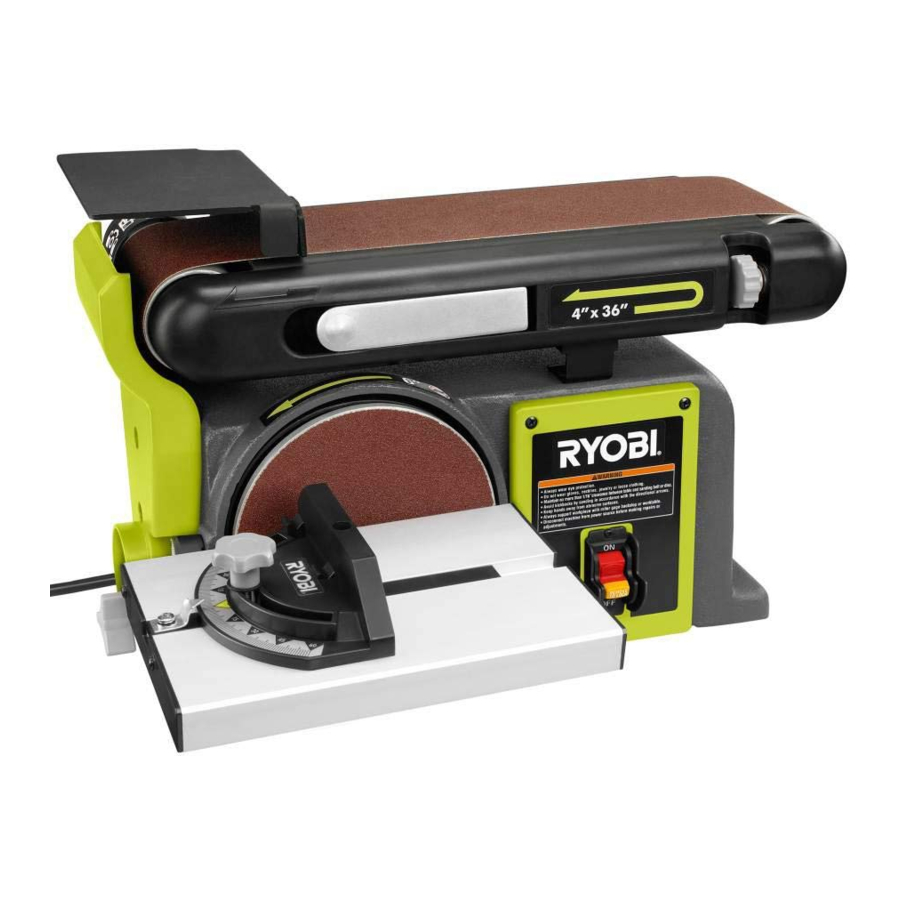
Belt Size: 4 in. x 36 in.
Belt Speed: 1,900 SFM
Belt Tilt: 0°- 90°
Disc Size: 6 in.
Disc Speed: 3,600 r/min. (RPM)
Table Size: 8-7/8 in. x 6-1/4 in.
Table Tilt: 0°- 45°
Input: 120 V, AC only, 60 Hz, 4.3 Amps
Motor: 1/2 HP
KNOW YOUR BELT/DISC SANDER

- Work support
- Tracking knob
- Belt tension lever
- Switch and switch key
- Sanding disc
- Bevel scale
- Miter gauge
- Sanding belt
- Work table
- Positioning bolt
The safe use of this product requires an understanding of the information on the tool and in this operator's manual as well as a knowledge of the project you are attempting. Before use of this product, familiarize yourself with all operating features and safety rules.
BELT TENSION LEVER
The belt tension lever releases the belt tension for easy belt replacement.
BEVEL SCALE
The worktable comes equipped with a bevel scale that indicates the degrees the worktable can be tilted up to 45°.
MITER GAUGE
The miter gauge aligns the wood for positive stops at 90° and 45°.
POSITIONING BOLT
Loosen the positioning bolt to change sanding belt positions from horizontal to vertical.
SANDING BELT
The sanding belt can be adjusted from horizontal to vertical providing different positions for sanding workpieces of different shapes and sizes.
SANDING DISC
A round sanding disc is located on the side of the belt/disc sander.
SWITCH AND SWITCH KEY
Your belt/disc sander has an easy access power switch.
TRACKING KNOB
A tracking knob aids in centering the sanding belt.
WORK SUPPORT (BACKSTOP)
Supports the workpiece on the sanding belt.
WORK TABLE
Equipped with a sturdy work table that provides a stable surface when using either the disc sanding or the belt sanding feature.
ASSEMBLY
LOOSE PARTS LIST

The following items are included with the saw:
| Key No. | Description | Qty. |
| A | Work table | 1 |
| B | Miter gauge | 1 |
| C | Sanding disc | 1 |
| D | Socket head screws | 2 |
| E | Disc guard | 1 |
| F | Phillips screw | 2 |
| G | Work support | 1 |
| H | Hex key | 1 |
| I | Washers | 2 |
| J | Washer | 1 |
| K | Table lock knob | 1 |
| Operator's Manual (not shown) | 1 |
UNPACKING
This product requires assembly.
- Carefully lift sander from carton and place on a level work surface.
Do not use this product if any parts on the Loose Parts List are already assembled to your product when you unpack it. Parts on this list are not assembled to the product by the manufacturer and require customer installation. Use of a product that may have been improperly assembled could result in serious personal injury.
- Inspect the tool carefully to make sure no breakage or damage occurred during shipping.
- Do not discard the packing material until you have carefully inspected and satisfactorily operated the product.
- The sander is factory set for accurate sanding. After assembling it, check for accuracy. If shipping has influenced the settings, take to an authorized service center.
- If any parts are damaged or missing, please call 1-800-525-2579 for assistance.
- If any parts are damaged or missing do not operate this product until the parts are replaced. Use of this product with damaged or missing parts could result in serious personal injury.
- Do not attempt to modify this product or create accessories not recommended for use with this tool. Any such alteration or modification is misuse and could result in a hazardous condition leading to possible serious personal injury.
- Do not connect to power supply until assembly is complete. Failure to comply could result in accidental starting and possible serious personal injury.
INSTALLING SANDING DISC AND DISC GUARD

- Sanding disc
- Disc guard
- Phillips screws
- Remove the backing from the sanding disc.
- Align perimeter of sanding disc with plate and press firmly into position.
- Position disc guard against the lower one-third of the disc aligning holes.
- Using the two phillips head screws, securely tighten the disc guard in place.
INSTALLING/REPLACING SANDING BELT

- Drive roller
- Idler roller
- Belt tension lever
- Sanding belt
- Directional arrow
On the smooth side of the sanding belt, there is a directional arrow. The sanding belt must run in the direction of the arrow.
- Using the hex key provided, loosen the positioning bolt by turning the bolt counterclockwise.
- Move the sanding belt into a vertical position.
- Lock the sanding belt by retightening the positioning bolt.
- Pull the belt tension lever toward you to release the belt tension.
- Place the sanding belt over the drive roller and idler roller with the directional arrows running counterclockwise. Be sure the sanding belt is centered on both drums.
- Push the belt tension lever back into place to apply the belt tension.
NOTE: The belt tension lever is spring loaded; use extreme caution when pushing the tension lever back into place to avoid personal injury.
MOUNTING THE WORK TABLE FOR USE WITH THE DISC SANDER

- Table lock knob
- Index pin
- Work table
- Washer
- Insert the work table index pin into the hole in the tool's housing.
- Position a washer over the table lock knob then tighten the table lock knob securely.
MOUNTING THE WORK TABLE FOR USE WITH THE BELT SANDER

- Table lock knob
- Work table
- Washer
- Index pin
- Insert the work table index pin into the hole in the sanding belt arm.
- Position a washer over the table lock knob then tighten the table lock knob securely.
ASSEMBLING WORK SUPPORT

- Washers
- Socket head screws
- Work support
- Place the work support over the holes in the side of the sanding belt arm.
- Using a hex key, fasten in place with washers and socket head screws.
MOUNTING BELT/DISC SANDER TO WORK-BENCH

- Bolt
- Lock washer
- Hex nut
If the belt/disc sander is to be used in a permanent location, it is recommended you secure it to a workbench or other stable surface. When mounting the belt/disc sander to a workbench, holes should be drilled through the supporting surface of the workbench.
- Mark holes on workbench where belt/disc sander is to be mounted using holes in the base as a template for hole pattern.
- Drill holes through workbench.
- Place belt/disc sander on workbench aligning holes in the base with holes drilled in the workbench.
- Insert bolts (not included) and tighten securely with lock washers and hex nuts (not included).
CLAMPING BELT/DISC SANDER TO WORKBENCH

- Mounting board
- C-clamps
If the belt/disc sander is to be used as a portable tool, it is recommended you fasten it permanently to a mounting board that can easily be clamped to a workbench or other stable surface. The mounting board should be of sufficient size to avoid tipping while belt/disc sander is in use. Any good grade plywood or chipboard with a 3/4 in. thickness is recommended.
- Mark holes on board where belt/disc sander is to be mounted using holes in the base as a template for hole pattern.
- Follow the last three steps in section Mounting Belt/Disc Sander to Workbench.
If lag bolts are used, make sure they are long enough to go through holes in belt/disc sander base and material the belt/disc sander is being mounted to. If machine bolts are used, make sure bolts are long enough to go through holes in belt/disc sander, the material being mounted to, and the lock washers and hex nuts.
OPERATION
- Do not allow familiarity with tools to make you careless. Remember that a careless fraction of a second is sufficient to inflict serious injury.
- Always wear eye protection with side shields marked to comply with ANSI Z87.1. Failure to do so could result in objects being thrown into your eyes, resulting in possible serious injury.
- Do not use any attachments or accessories not recommended by the manufacturer of this tool. The use of attachments or accessories not recommended can result in serious personal injury.
APPLICATIONS
This product has been designed only for the purposes listed below:
- Sanding and finishing plastic, wood, and wood composition materials
- Bevel sanding
- Horizontal and vertical sanding
- Sanding curved pieces
- Applying the workpiece to the right side of the sanding disc could cause the workpiece to kickback and/or loss of control. Failure to heed this warning could result in serious personal injury.
- Do not reach across the sanding disc to turn the belt/ disc sander ON or OFF. Contact with the sanding disc can result in serious personal injury.
POWER SWITCH

- Switch on
- Switch off
- Switch key removed
The belt/disc sander is equipped with a power switch that has a built-in locking feature. This feature is intended to prevent unauthorized and possible hazardous use by children and others.
TO TURN THE BELT/DISC SANDER ON:
- With the switch key inserted into the switch, lift the switch button to turn ON.
TO TURN THE BELT/DISC SANDER OFF:
- Press the switch button down to turn OFF.
- ALWAYS remove the switch key when the tool is not in use and keep it in a safe place. In the event of a power failure, turn the switch OFF and remove the key. This action will prevent the tool from accidentally starting when power returns.
- ALWAYS make sure your workpiece is not in contact with the belt before operating the switch to start the tool. Failure to heed this warning may cause the workpiece to be kicked back toward the operator and result in serious personal injury.
- To reduce the risk of accidental starting, ALWAYS make sure the switch is in the OFF position before plugging tool into the power source.
LOCKING THE SWITCH

- Switch key
- "No Hands" label
- Place the switch in the OFF position.
- Wait until the belt/disc sander has come to a full and complete stop.
- Remove the switch key from the switch assembly. Store key in safe place.
BEVEL SANDING

- Table lock knob

The worktable can be tilted from 0° to 45° for bevel sanding. For angles 30º and above, position sander to the edge of the work bench and mount sander in place as shown in figures 9 and 10.
To tilt the worktable:
- Loosen the table lock knob by turning it counterclockwise.
- Set worktable to desired angle.
- Tighten the table lock knob by turning it clockwise.
SANDING SMALL END SURFACES USING THE MITER GAUGE

- Miter gauge
- Directional arrows
A miter gauge is included with the tool for increased accuracy. Use of a miter gauge is recommended for sanding small end surfaces on the sanding disc.
NOTE: Always move the workpiece across the sanding disc from the left side toward the center.
HORIZONTAL AND VERTICAL SANDING

- Vertical position
- Positioning bolt
- Horizontal position
The belt/disc sander can sand both vertically and horizontally. Depending on the workpiece, use the work support for horizontal sanding operations and use the work table for vertical sanding operations.
- Using the hex key provided, loosen the positioning bolt by turning the bolt counterclockwise.
- Move the sanding belt into a vertical position.
- Lock the sanding belt by retightening the positioning bolt.
NOTE: Sand long workpieces with the sanding belt in the vertical position by moving the work evenly across the sanding belt.
ALWAYS use the work support for horizontal sanding and use the work table for vertical sanding. Using the sander without also using the work support or work table may expose the operator to pinch points and could result in serious personal injury.
SURFACE SANDING ON THE SANDING BELT

- Work support
- Workpiece
- Hold the workpiece firmly, keeping fingers away from the sanding belt.
- Keep the end pressed firmly against the work support moving work evenly across the sanding belt.
NOTE: Use extra caution when sanding very thin pieces. When sanding extra long pieces, move the work piece across the belt while applying only enough pressure to allow the sanding belt to remove the material.
SANDING CURVED PIECES

- Workpiece
- Idler roller
- Belt direction towards work support

- Workpiece
Never attempt to sand the end pieces of a workpiece on the idler drum. Applying the end of the workpiece on the idler drum could cause the workpiece to fly up. Failure to heed this warning could result in serious personal injury.
Sanding inside curves on the sanding belt:
Always sand inside curves on the idler drum.
- Hold the workpiece firmly, keeping fingers away from the sanding belt.
- Keep the curve pressed firmly against the idler drum moving work evenly across the sanding belt.
![warning]() NOTE: Use extra caution when sanding very thin pieces and apply only enough pressure to allow the sanding belt to remove the material.
NOTE: Use extra caution when sanding very thin pieces and apply only enough pressure to allow the sanding belt to remove the material.
Sanding outside curves on the sanding disc:
Always sand outside curves using the sanding disc and moving the workpiece from the left side of center.
- Hold the workpiece firmly, keeping fingers away from the sanding disc.
- Keep the curve pressed firmly against the sanding disc moving work evenly on the left side of the sanding disc.
NOTE: Always move the workpiece across the sanding disc from the left side toward the center.
ADJUSTMENTS
Before performing any adjustment, make sure the tool is unplugged from the power supply and the switch is in the OFF ( O ) position. Failure to heed this warning could result in serious personal injury.
ADJUSTING THE BELT TRACKING
![]()
- Tracking knob
- Switch
- Plug in belt/disc sander.
To check belt tracking:
- Turn the switch ON and then immediately turn it OFF. If the belt tends to slide off the idler drum or drive drum, the belt is not tracking properly.
To adjust belt tracking:
- If the sanding belt moves toward the disc, turn the tracking knob up 1/4 turn.
- If the sanding belt moves away from the disc, turn the tracking knob down 1/4 turn.
- Turn the switch ON and then immediately OFF again, noting belt movement. Readjust tracking knob if necessary.
SQUARING THE WORKTABLE TO THE SANDING DISC

- Table lock knob
- Combination square
- Unplug the belt/disc sander.
- Using a combination square, check the angle of the worktable with the sanding belt.
- If the work table is not 90° with the disc, loosen the table lock knob and tilt the table.
- Adjust work table square to the sanding disc and retighten the table lock knob.
MAINTENANCE
- When servicing, use only identical replacement parts. Use of any other parts may create a hazard or cause product damage.
- Always wear eye protection with side shields marked to comply with ANSI Z87.1 during product operation. If operation is dusty, also wear a dust mask.
- Before performing any maintenance, make sure the tool is unplugged from the power supply and the switch is in the off ( O ) position. Failure to heed this warning could result in serious personal injury.
GENERAL MAINTENANCE
Avoid using solvents when cleaning plastic parts. Most plastics are susceptible to damage from various types of commercial solvents and may be damaged by their use. Use clean cloths to remove dirt, dust, oil, grease, etc.
Do not at any time let brake fluids, gasoline, petroleum-based products, penetrating oils, etc., come in contact with plastic parts. Chemicals can damage, weaken or destroy plastic which may result in serious personal injury.
LUBRICATION
All of the bearings in this tool are lubricated with a sufficient amount of high grade lubricant for the life of the unit under normal operating conditions. Therefore, no further lubrication is required.
CHANGING DRIVE BELT

- Phillips screw
- Belt cover
- Drive belt
- Motor pulley
- Drive pulley
- Tension screw
- Pulley housing
- Unplug the belt/disc sander.
- Using a phillips head screwdriver, remove the screw in the center of the belt cover.
- Remove the cover.
- Loosen the three tension screws inside the pulley housing then push the housing down to loosen the belt tension.
- Remove the old drive belt.
- Fit the new drive belt on the drive pulley first then on the motor pulley.
- Test belt tension by squeezing the belt with your fingers.
- Push the pulley housing up to increase belt tension until there is about 1/4 inch of give.
- Tighten the tension screws securely.
- Using a phillips head screwdriver, reinstall the pulley cover and the screw. Tighten securely.
Documents / ResourcesDownload manual
Here you can download full pdf version of manual, it may contain additional safety instructions, warranty information, FCC rules, etc.
Advertisement


Need help?
Do you have a question about the BD4601 and is the answer not in the manual?
Questions and answers