Advertisement
SAFETY INFORMATION
 TO REDUCE RISK OF INJURY:
Before any use be sure everyone using this product reads and understands all safety instructions and other information contained in this manual

Wear appropriate personal hearing protection during use. Under some conditions and duration of use, noise from this product may contribute to hearing loss.

When using electric gardening appliances, basic safety precautions should always be followed to reduce risk of fire, electric shock, and personal injury, including the following: READ ALL INSTRUCTIONS
GENERAL SAFETY
- CHECK FOR DAMAGED PARTS - Before further use of the product, any part that is damaged should be carefully checked to determine that it will operate properly and perform its intended function. Check for alignment of moving parts, binding of moving parts, breakage of parts, mounting and any other condition that may affect its operation. Any part that is damaged should be properly repaired or replaced.
- AVOID DANGEROUS ENVIRONMENTS - Don't use this product in rainy, stormy, damp or wet locations. Do not operate in gaseous or explosive atmospheres. Motors in these products normally spark, and the sparks might ignite fumes.
- KEEP CHILDREN AWAY - All visitors, children and pets should stay at a safe distance from the work area.
- DRESS PROPERLY- Don't wear loose clothing or jewelry and wear protective hair covering to contain long hair. They can be caught in moving parts. Use of rubber gloves and substantial footwear is recommended when working outdoors.
- USE SAFETY GLASSES - Wear safety glasses with side shields or goggles when operating this product. Use face or dust mask if environment is dusty.

DOUBLE INSULATION - The tiller/cultivator has double insulation. This means that all external metal parts are insulated from the electrical supply. This is achieved by introducing an insulation layer between electrical and mechanical parts. The double insulation guarantees you the greatest possible safety.
- EXTENSION CORD. Make sure your extension cord is in good condition. When using an extension cord be sure it is heavy enough to carry the current your product will draw. An undersized extension cord will cause a drop in line voltage resulting in loss of power and overheating.
- It is possible to tie the extension cord and power cord in a knot to prevent them from becoming disconnected during use. Make the knot as shown, then connect the plug end of the power cord into the receptacle end of the extension cord. This method can also be used to tie two extension cords together.
![]()

| Volts | Total length of cord feet | |||||
| 120V | 25 | 50 | 100 | 150 | ||
| Ampere rating more than | Ampere rating not more than | AWG | ||||
| 0 - 6 | 18 | 16 | 16 | 14 | ||
| 6 - 10 | 18 | 16 | 14 | 12 | ||
| 10 - 12 | 16 | 16 | 14 | 12 | ||
| 12 - 16 | 14 | 12 | Not Recommended | |||
- Be aware of the extension cord while operating the tiller/cultivator. Be careful not to trip on the cord. Always guide the cord away from the tines.
- Avoid Unintentional Starting - Don't carry plugged-in appliance with finger on switch, Be sure switch is off when plugging in. Don't grasp the exposed cutting tines or cutting edges when picking up or holding the appliance. Don't Force Appliance - It will do the job better and with less likelihood of a risk of injury at the rate for which it was designed. Keep hands away from tines.
- GROUND FAULT CIRCUIT INTERRUPTER (GFCI)
- Protection should be provided on the circuit or outlet to be used for the tiller/cultivator. Receptacles are available having built-in GFCI protection and may be used.
- DISCONNECT UNIT from the power supply when not in use or when servicing or cleaning. Do not leave unattended.
- DON'T ABUSE CORD - Never carry this product by the cord or yank the cord to disconnect from the receptacle. Keep cord from heat, oil, and sharp edges.
- USE RIGHT APPLIANCE - Do not use this product for any job except that for which it is intended.
- DON'T OVERREACH - Guide the tiller/cultivator at a walking pace only. Keep proper footing and balance at all times.
- LIGHTING - Only operate your tiller/cultivator in daylight or good artificial light.
- STORE IDLE UNIT INDOORS-When not in use, the tiller/cultivator should be stored indoors in a dry area out of children's reach.
- MAINTAIN UNIT WITH CARE-Keep clean for best performance and to reduce the risk of injury. Inspect extension cord periodically and replace if damaged. Keep handles dry, clean and free from oil.
- POLARIZED PLUGS-To reduce the risk of electric shock, this product has a polarized plug. Polarized connections will fit together only one way. Make sure that the receptacle end of the extension cord has large and small blade slot widths. If the plug does not fit fully into the extension cord, reverse the plug. If it still does not fit, obtain a suitable extension cord. If the extension cord does not fit fully into the outlet, contact a qualified electrician to install the proper outlet. Do not change the plug on the tool or the extension cord in any way.
- Do not operate the tiller/cultivator on a slope that is too steep for safe operation. When on slopes, slow down and make sure you have good footing. Before starting the tiller/cultivator make sure the times are not touching any object and are free to move. Grip the guide bar firmly with both hands. Never operate the tiller/cultivator with one hand.
The tiller/cultivator may bounce upward and/or jump forward if the tines strike extremely hard packed soil, frozen ground, or buried obstacles such as large stones, roots or stumps.
- STAY ALERT - Watch what you are doing. Use common sense. Do not operate the tiller/cultivator when you are tired or under the influence of drugs or medication.
Do not operate the tiller/cultivator near underground electrical cables, telephone lines, pipes or hoses. If the tiller/cultivator strikes a foreign body, turn it off immediately, wait for the tines to stop and check for damage. If necessary, repair before restarting. If the tiller/cultivator starts to vibrate abnormally, turn it off immediately and check for the cause. Vibration is generally a warning of trouble.

RISK OF CUT - Wear gloves and use caution when cleaning or performing maintenance on the tiller/cultivator. Always turn off the tiller/cultivator, disconnect from the power supply and wait until the tines come to a complete stop before carrying out any maintenance or repairs.
Tines do not stop immediately after the tiller/cultivator is turned off.
Risk of injury. Do not put hands, feet or any body part or clothing near the rotating tines.
he electrical cords on this product may contain chemicals known to the State of California to cause cancer and birth defects or other reproductive harm. Wash hands after handling.
Some dust and debris created by the use of this tool could contain chemicals known to the State of California to cause cancer and birth defects or other reproductive harm. Some examples of these chemicals are:
- chemicals in fertilizers
- compounds in insecticides, herbicides, and pesticides
- arsenic and chromium from chemically treated lumber
Your risk from exposure to these chemicals varies, depending on how often you do this type of work. To reduce your exposure, work in a well-ventilated area and with approved safety equipment such as dust masks that are specially designed to filter out microscopic particles.
SPECIFIC SAFETY INFORMATION
Training
- Read the operating and service instruction manual carefully. Be thoroughly familiar with the controls and the proper use of the equipment. Know how to stop the unit and disengage the controls quickly.
- Never allow children to operate the equipment. Never allow adults to operate the equipment without proper instruction.
- Keep the area of operation clear of all persons, particularly small children, and pets.
- Keep in mind that the operator or user is responsible for accidents or occurring to other people, their property, and themselves.
Preparation
- Thoroughly inspect the area where the equipment is to be used and remove all foreign objects.
- Disengage all clutches and shift into neutral before starting the motor.
- Do not operate the equipment without wearing adequate outer garments. Wear protective footwear that will improve footing on slippery surfaces.
- Use extension cords and receptacles as specified by the manufacturer for all units with electric drive motors or electric starting motors.
- Never attempt to make any adjustments while the motor is running.
Operation
- Do not put hands or feet near or under rotating parts.
- Exercise extreme caution when operating on or crossing gravel drives, walks, or roads. Stay alert for hidden hazards or traffic. Do not carry passengers.
- After striking a foreign object, stop the motor, thoroughly inspect the machine for any damage, and repair the damage before restarting and operating the machine.
- Exercise caution to avoid slipping or falling.
- If the unit should start to vibrate abnormally, stop the motor and check immediately for the cause. Vibration is generally a warning sign of trouble.
- Stop the motor when leaving the operating position, before unclogging the tines, and when making any repairs, adjustments, and inspections.
- Take all possible precautions when leaving the machine unattended. Disengage the power take-off, lower the attachment, shift into neutral, stop the motor, and remove the key if applicable.
- Before cleaning, repairing, or inspecting, shut off the motor and make certain all moving parts have stopped.
- Never operate the machine without proper guards, plates, or other safety protective devices in place.
- Keep children and pets away.
- Do not overload the machine capacity by attempting to till too deep at too fast a rate.
- Never operate the machine at high transport speeds on hard or slippery surfaces.
- Never allow bystanders near the unit.
- Use only attachments and accessories approved by the manufacturer of the machine (such as wheel weights, counterweights, and the like).
- Never operate the tiller without good visibility or light.
- Be careful when tilling in hard ground. The tines may catch in the ground and propel the tiller forward. If this occurs, let go of the handlebars and do not restrain the machine.
- Use extreme caution when reversing or pulling the machine towards you.
- Switch on the motor carefully according to instructions and with feet well away from the tines.
- Never pick up or carry a machine while the motor is running.
- Do not operate the tiller while under the influence of alcohol or drugs.
Maintenance and Storage
- Keep machine, attachments, and accessories in safe working condition.
- Check shear bolts, and other bolts at frequent intervals for proper tightness to be sure the equipment is in safe working condition.
- Always refer to the operator's manual for important details if the tiller is to be stored for anextended period.
- Follow manufacturer's recommendations for safe loading, unloading, transport, and storage of machine.
SYMBOLS
Some of the following symbols may be used on this product. Please study them and learn their meaning. Proper interpretation of these symbols will allow you to operate the product better and safer.
| SYMBOL | NAME | DESIGNATION/EXPLANATION |
| V | Volts | Voltage |
| A | Amperes | Current |
| Hz | Hertz | Frequency (cycles per second) |
| W | Watts | Power |
| min | Minutes | Time |
 | Alternating Current | Type of current |
 | Direct Current | Type or a characteristic of current |
| no | No Load Speed | Rational speed, at no load |
 | Class II Construction | Double-insulated construction |
| /min | Per Minute | Revolutions, strokes, surface speed, orbits etc., per minute |
 | Wet Conditions Alert | Do not expose to rain or use in damp locations |
 | Read The Operator's Manual | To reduce the risk of injury user must read and understand operator's manual before using this product. |
 | Eye Protection | Wear eye protection when operating this equipment. |
 | Ricochet | Thrown objects can ricochet and result in personal injury or property damage. |
 | Sharp Blade |  Danger – Keep hands and feet away from blade. Danger – Keep hands and feet away from blade. |
 | Keep Bystanders Away | Keep all bystanders at least 50 ft. away. |
The following signal words and meanings are intended to explain the levels of risk associated with this product.
| SYMBOL | MEANING |
| | Indicates an imminently hazardous situation, which, if not avoided, will result in death or serious injury. |
| | Indicates a potentially hazardous situation, which, if not avoided, could result in death or serious injury. |
| | Indicates a potentially hazardous situation, which, if not avoided, may result in minor or moderate injury. |
| CAUTION | (Without Safety Alert Symbol) Indicates a situation that may result in property damage. |
SERVICE
Servicing requires extreme care and knowledge and should be performed only by a qualified service technician. For service we suggest you return the product to your nearest AUTHORIZED SERVICE CENTER for repair. When servicing, use only identical replacement parts.
To avoid serious personal injury, do not attempt to use this product until you have read this Owner's Manual thoroughly and understand it completely. If you do not understand the warnings and instructions in this Owner's Manual, do not use this product. Call the Toll-free Helpline (1-866-384-8432) for assistance.

The operation of any power tool can result in foreign objects being thrown into your eyes, which can result in severe eye damage. Before beginning power tool operation, always wear safety goggles or safety glasses with side shields and, when needed, a full face shield. We recommend Wide Vision Safety Mask for use over eyeglasses or standard safety glasses with side shields. Always use eye protection which is marked to comply with ANSI Z87.1.
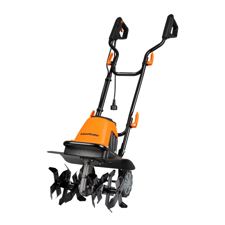
KNOW YOUR TILLER / CULTIVATOR

- Main Handle
- Cord Retainer
- Power Plug
- Cable Clip
- Upper Handle Assembly
- Cam Lock Assembly
- Center Handle Section
- Motor Housing
- Motor Support Plate
- Lower Handle Section
- Tine Assembly right/left
- Transport Wheels
- R Clip
- Locking Button
UNPACK
- Unpack all parts and lay them on a flat, stable surface.
- Remove all packing materials and shipping devices if applicable.
- Make sure the delivery contents are complete and free of any damage. If you find that parts are missing or show damage do not use the product but contact your dealer. Using an incomplete or damaged product represents a hazard to people and property.
- Ensure that you have all the accessories and tools needed for assembly and operation. This also includes suitable personal protective equipment.
You Will Need (items not supplied)
- Suitable personal protective equipment
- Philips screwdriver
(Item supplied)
- Tiller unit
- Upper handle assembly
- Lower handle assembly
- Hardware pack
- Bolt M6 X 57 X 4
- Plane washer O6 X 4
- Camlock X 4
- Wheel X 2
- Wheel cap X 2
- Cable Clip X 2
- Below parts are assembled on the Tiller in package:
- Plane washer O5 X 2
- Wave washer O5 X 2
- Screw M5X12 X 2
ASSEMBLY

This product must be assembled correctly before use.
- Remove the plane washers (
![]() 5), wave washers (
5), wave washers (![]() 5) and screws ( M5x12 ) from wheel axis of tiller then place one wheel (12) over each side of axle, then attach using plane washer (
5) and screws ( M5x12 ) from wheel axis of tiller then place one wheel (12) over each side of axle, then attach using plane washer (![]() 5) wave washer (
5) wave washer (![]() 5) and screws ( M5x12 ) to secure (Fig1-1).
5) and screws ( M5x12 ) to secure (Fig1-1).

- Press the wheel covers into the wheel and cover the ends of the axles. A rubber mallet may be used to seat them securely onto the wheels (Fig1-1).
- Attach the center handle section (7) to the lower handle section (10) using the two supplied bolts, washers and camlocks (6) (Fig.1-2).
![]()
- Fasten the upper handle section (5) to the center handle section (7) using the two supplied bolts and camlock and washer (6) (Fig.1-3).
![]()
- Use the two supplied cable clips (4) to secure the cord (Fig.1-4).
![]()


If any parts are damaged or missing do not operate this product until the parts are replaced. Failure to heed this warning could result in serious personal injury. Call our customer service help line.
Do not attempt to modify this product or create accessories not recommended for use with this product. Any such alteration or odification is misuse and could result in a hazardous condition leading to possible serious personal injury.
Do not connect to power supply until assembly is complete. Failure to comply could result in accidental starting and possible serious personal injury.
OPERATING
STARTING
- Make sure the wheel frame is raised before you start the tiller. To raise the frame, pull out the Locking button (Step A); rotate the wheel frame upward (Step B); release the Locking button. The wheel frame will be locked in place by the Locking button (Fig.2).

- Secure the extension cord into the cord retainer (2). The loop of the extension cord must be long enough for the cord retainer to freely slide from one side to the other. Plug the extension cord into the power cord plug on the tiller (Fig.3).
![]()
- Use the tiller/cultivator for breaking sod, preparing seed beds, and for cultivating gardens and flower beds. The tiller/cultivator can also dig small holes for planting saplings or potted plants.
- Move the tiller/cultivator to the work area prior to starting the motor.
- Hold the tiller/cultivator firmly while starting. The tines will pull the tiller/cultivator forward during operation.
- Lower the tines slowly with the guide bar.


TO START THE TILLER / CULTIVATOR PRESS THE SAFETY Locking button

- (A) Depress the safety switch and then pull the trigger lever.
(B) Pull the trigger lever up and against the motor will start and the tines will begin to rotate. - To stop the tiller/cultivator simply release the lever.
- For breaking sod or deep tilling, allow the tines to pull the tiller/cultivator forward to the end of your arm's reach, then firmly pull it back toward yourself. You will achieve the best results by repeatedly allowing it to move forward and pulling it back.
- By pulling the tiller/cultivator back towards yourself, the tines will dig deeper and more aggressively.
- To prevent tripping, take extra precautions when moving backwards and when pulling the tiller / cultivator back toward yourself.
- If the tiller/cultivator digs deep enough to stay in one spot, gently rock it side to side until it starts moving forward again. Never pass the tiller/cultivator over the extension cord.
- Make sure the cord is always in a safe position behind you.
- When working on inclines always stand diagonally to the incline to retain a firm, safe footing.
- Do not work on extremely steep slopes.
FOR PREPARING SEED BEDS, WE RECOMMEND USING ONE OF THESE TILLING PATTERNS :

Tilling Pattern A- Make two passes over area to be tilled, the second at a right angle to the first.
Tilling Pattern B- Make two passes over area to be tilled, the second overlapping the first.
Before use, remove any visible stones or other foreign bodies from the area.
Before moving the tiller/cultivator from one area to another switch off the motor and wait for the tines to come to a complete stop. Be careful not to let the tines touch the ground while moving the tiller/cultivator. The tines as well as the unit itself may be damaged even if the motor is switched off.
CLEARING FOREIGN OBJECTS:
During operation a stone or root could become lodged in the tines, or tall grass or weeds may become wrapped around the tine shaft.
To clear the tines or tine shaft release the trigger lever, wait for the tines to come to a complete stop and unplug the tiller/cultivator. Dislodge or remove the foreign matter from the tines or tine shaft. To simplify removal of tall grass or weeds from the tine shaft, remove one or more of the tines. See Tine Removal and Installation.
MAINTENANCE
BEFORE CARRYING OUT MAINTENANCE OPERATIONS, DISCONNECT POWER SUPPLY.
Before each use check the extension cord for signs of damage or ageing. Replace the cable if it is cracked, split or otherwise damaged. Check the condition of the tines and ensure that all threaded connections are securely tightened. If the tines become dull or blunt, sharpen or replace them. Call our customer service help line. Once per season lubricate the tines and shaft. At the end of the season, check the tiller/cultivator for damage prior to storing. Repair or replace damaged or broken parts.
Always clean the tiller/cultivator after each use. Failure to carry out proper cleaning can result in damage to the tiller/cultivator or result in poor performance.
Clean the underside of the motor support plate and housing around the tines with a scrub brush, and a soft cloth dampened with a mild soap and water mixture. Never use a water hose to clean the tiller! To remove soil and debris from the transmission and tines, use a stiff brush or a dampened cloth. Clean the vents on the motor housing and remove any remaining grass or dirt. Once cleaned, wipe the tines and shaft dry and apply a light coat of oil to prevent rust.
TINE REMOVAL AND INSTALLATION
Worn tines invite poor performance and overload of the motor. Check tines before each use. Sharpen or replace the tine assemblies with new ones when necessary. To remove the complete tine assemblies from the shaft, remove the R Clip(13) from the shaft first. Reverse above steps to install tines. These 6 tines have different shapes. Each tine is stamped with its own identifier code (A,A1,A2,B,B1,B2). You should install tine assemblies with a sequence according Fig6.

Injury can occur while working on the tines. Wear protective gloves. To remove the complete tine assemblies from the shaft, remove the B shape fixed pin 13 from the shaft. Remove the tine assembly from the shaft. Reverse above steps to install tines.
ADDING TRANSMISSION LUBRICANT
Drain screw plug is located on the right side of transmission housing. Lay the tiller/cultivator on its left from user's perspective side and clean the transmission of dirt and debris prior to removing the drain screw plug. If necessary, remove tine assemblies to have better access to the drain screw plug. Use a 5mm hex key to unscrew the plug. Empty the oil from the transmission. Fill with a high-quality SAE 30 weight oil, until it begins to seep out around the hole. Reinstall the drain screw plug.

STORAGE
Store the Tiller/Cultivator in a dry, clean area out of reach of children. During extended periods of storage, ensure that the tiller/ cultivator is protected against corrosion and frost.
At the end of the season, or if the tiller/cultivator is not being used for longer than a month, wipe over all metal surfaces with an oil impregnated cloth to protect them from corrosion or spray with a fine coat of oil. Fold the guide bar down, and store the tiller/cultivator in a suitable place.
TROUBLESHOOTING
| Problem | Possible causes | Remedy |
Motor does not start | Unit not plugged in No electricity Defective cable Defective safety switch/plug Overheat protection activated | Plug in the unit Check power supply Check cable. Repair or replace if required Arrange for repair
|
Abnormal noises | Tine is jammed | Switch off. Wait till tines comes to a completes top. Remove jammed objects. |
| Lubrication running out | Tiller/cultivator must be repaired. Send in to Service Centre for repair. | |
| Bolts, nuts or other components are loose. | Tighten all components. Arrange for repair if noises continue. | |
Abnormal vibrations | Tines damaged or worn Working depth too large | Replace damaged or worn tines. Set to correct working depth |
Poor results | Working depth too small Worn tines | Set to correct working depth. Replace damaged or worn tines |
EXPLODED VIEW


PARTS LIST
| Part No. | Part Name | QTY' | Part No. | Part Name | QTY' |
| 1 | Screw M6x18 | 8 | 37 | Rotor Locating Plate | 1 |
| 2 | Washer 6mm | 8 | 38 | Bearing 6000 | 1 |
| 3 | Screw M10x10 | 1 | 39 | Rotor Assy | 1 |
| 4 | O-rings | 1 | 40 | Screw M5x85 | 2 |
| 5 | Right Gear Box | 1 | 41 | Elastic Gasket 5 | 4 |
| 6 | Gear Box Case Sealing Strips | 1 | 42 | Motor Support Base | 1 |
| 7 | Ball Bearing | 3 | 43 | Screw St4x12 | 2 |
| 8 | Worm Shaft | 1 | 44 | Screw St4x20 | 6 |
| 9 | Worm Wheel | 1 | 45 | Stator Assy | 1 |
| 10 | Sleeve | 1 | 46 | Motor Support Base | 1 |
| 11 | Thrust Bearing | 1 | 47 | Housing | 1 |
| 12 | Ball Bearing | 1 | 48 | Housing Cover | 1 |
| 13 | Spindle Sleeve | 2 | 49 | Carbon Brush Insert | 2 |
| 14 | Rubber Seal 14 | 1 | 50 | Carbon Brush | 2 |
| 15 | Rubber Seal Guard | 2 | 51 | Screw St3x8 | 2 |
| 16 | Flat Key 4x4x16 | 1 | 52 | Carbon Brush Frame | 2 |
| 17 | Washer 19 | 2 | 53 | Nut S=5.5 | 2 |
| 18 | Worm Wheel Shaft | 1 | 54 | Shaft | 1 |
| 19 | Oil Bearing | 2 | 55 | Steel Ball | 2 |
| 20 | Rubber Seal 19 | 2 | 56 | Sleeve | 1 |
| 21 | Left Gear Box | 1 | 57 | Spring | 1 |
| 22 | R Clip | 2 | 58 | Spring Holder | 1 |
| 23 | Nut M6 | 14 | 59 | Belt Roller | 1 |
| 24 | Coach Screw M6x20 | 8 | 60 | Ball Bearing | 1 |
| 25 | Safty Guard | 1 | 61 | Belt | 1 |
| 26 | Sponge Mat 1 | 1 | 62 | Support Base | 1 |
| 27 | Sponge Mat 2 | 1 | 63 | Shaft | 1 |
| 28 | Casing Seat | 1 | 64 | Coach Screw M6x35 | 2 |
| 29 | Screw M6*50 | 4 | 65 | Lower Handle Section | 1 |
| 30 | Chassis | 1 | 66 | Wheel Adjustment Plate | 1 |
| 31 | Screw St4x16 | 41 | 67 | Cable Clip | 2 |
| 32 | Corrugated Gasket | 4 | 68 | Center Handle Section | 1 |
| 33 | Cable Clamp | 3 | 69 | Corrugated Gasket | 1 |
| 34 | Cable Sleeve | 2 | 70 | Plug | 2 |
| 35 | Nut M8 | 1 | 71 | Red Steel Paper | 1 |
| 36 | Pinion | 1 | 72 | Axle Sleeve | 1 |
| A1 | Upper Handle Assembly w/Power Cord | 1 | A4 | Wheel Assembly | 2 |
| A2 | Cam Knob Assembly | 4 | A5 | Left Side Tine Assembly | 1 |
| A3 | Locking Axle Assembly | 1 | A6 | Right Side Tine Assembly | 1 |
Documents / ResourcesDownload manual
Here you can download full pdf version of manual, it may contain additional safety instructions, warranty information, FCC rules, etc.
Advertisement


Need help?
Do you have a question about the TE1016M and is the answer not in the manual?
Questions and answers