Table of Contents
Advertisement
Quick Links
Advertisement
Table of Contents

Related Manuals for LawnMaster TE1016M


Summary of Contents for LawnMaster TE1016M
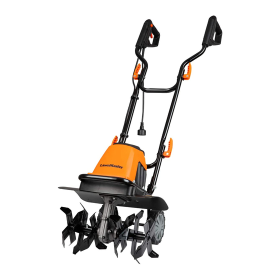
- Page 1 OPERATOR'S MANUAL EN p. 2 16 Inch / 10 Amp Tiller / Cultivator TE1016M TE1016M Read all safety rules and instructions carefully before operating this tool. Distributed By Cleva North America 601 Regent Park Court Greenville, SC 29607 (866)-384-8432...
-
Page 2: Table Of Contents
18-19 STORAGE TROUBLESHOOTING WARRANTY EXPLODED DIAGRAM 22-23 PARTS LIST NOTES PRODUCT SPECIFICATIONS Model : TE1016M Nominal Voltage : 120V~60Hz Tilling Width : 16” (400mm) Maximum Tilling Depth : 9” (220mm) Nominal Current : 10(A) Number of tines : Tine Diameter :... -
Page 3: Safety Information
SAFETY INFORMATION TO REDUCE RISK OF INJURY: Before any use be sure everyone using this product reads and understands all safety instructions and other information contained in this manual CAUTION: Wear appropriate personal hearing protection during use. Under some conditions and duration of use, noise from this product may contribute to hearing loss. - Page 4 SAFETY INFORMATION DOUBLE INSULATION - The tiller/cultivator has double insulation. This means that all external metal parts are insulated from the electrical supply. This is achieved by introducing an insulation layer between electrical and mechanical parts. The double insulation guarantees you the greatest possible safety.
- Page 5 SAFETY INFORMATION • DON'T ABUSE CORD - Never carry this product by the cord or yank the cord to disconnect from the receptacle. Keep cord from heat, oil, and sharp edges. • USE RIGHT APPLIANCE - Do not use this product for any job except that for which it is intended. •...
- Page 6 SAFETY INFORMATION WARNING: Do not operate the tiller/cultivator near underground electrical cables, telephone lines, pipes or hoses. If the tiller/cultivator strikes a foreign body, turn it off immediately, wait for the tines to stop and check for damage. If necessary, repair before restarting. If the tiller/cultivator starts to vibrate abnormally, turn it off immediately and check for the cause.
-
Page 7: Specific Safety Information
SPECIFIC SAFETY INFORMATION Training Read the operating and service instruction manual carefully. Be thoroughly familiar with the controls and the proper use of the equipment. Know how to stop the unit and disengage the controls quickly. Never allow children to operate the equipment. Never allow adults to operate the equipment without proper instruction. - Page 8 SPECIFIC SAFETY INFORMATION Never operate the machine without proper guards, plates, or other safety protective devices in place. Keep children and pets away. Do not overload the machine capacity by attempting to till too deep at too fast a rate. Never operate the machine at high transport speeds on hard or slippery surfaces.
-
Page 9: Symbols
SYMBOLS Some of the following symbols may be used on this product. Please study them and learn their meaning. Proper interpretation of these symbols will allow you to operate the product better and safer. SYMBOL NAME DESIGNATION/EXPLANATION Volts Voltage Amperes Current Hertz Frequency (cycles per second) - Page 10 SYMBOLS The following signal words and meanings are intended to explain the levels of risk associated with this product. SYMBOL SIGNAL MEANING Indicates an imminently hazardous situation, which, if DANGER not avoided, will result in death or serious injury. Indicates a potentially hazardous situation, which, if not WARNING avoided,could result in death or serious injury.
-
Page 11: Know Your Tiller / Cultivator
KNOW YOUR TILLER / CULTIVATOR 1 Main Handle 8 Motor Housing 2 Cord Retainer 9 Motor Support Plate 3 Power Plug 10 Lower Handle Section 11 Tine Assembly (right/left) 4 Cable Clip 5 Upper Handle Assembly 12 Transport Wheels 6 Cam Lock Assembly 13 R Clip 7 Center Handle Section 14 Locking Button... -
Page 12: Unpack
UNPACK Unpack all parts and lay them on a flat, stable surface. Remove all packing materials and shipping devices if applicable. Make sure the delivery contents are complete and free of any damage. If you find that parts are missing or show damage do not use the product but contact your dealer. Using an incomplete or damaged product represents a hazard to people and property. -
Page 13: Assembly
ASSEMBLY M6X57 M6X57 O5 M5X12 Fig.1... - Page 14 ASSEMBLY This product must be assembled correctly before use. 1. Remove the plane washers (O5) ,wave washers (O5) and screws ( M5x12 ) from wheel axis of tiller,then place one wheel (12) over each side of axle, then attach using plane washer (O5) ,wave washer (O5) and screws ( M5x12 ) to secure (Fig1-1).
-
Page 15: Operating
OPERATING STARTING: 1. Make sure the wheel frame is raised before you start the tiller. To raise the frame, pull out the Locking button (Step A); rotate the wheel frame upward (Step B); release the Locking button. The wheel frame will be locked in place by the Locking button (Fig.2). 2. - Page 16 OPERATING 5. To prevent tripping, take extra precautions when moving backwards and when pulling the tiller / cultivator back toward yourself. 6. If the tiller/cultivator digs deep enough to stay in one spot, gently rock it side to side until it starts moving forward again.
- Page 17 OPERATING Before use, remove any visible stones or other foreign bodies from the area. CAUTION: Before moving the tiller/cultivator from one area to another switch off the motor and wait for the tines to come to a complete stop. Be careful not to let the tines touch the ground while moving the tiller/cultivator.
-
Page 18: Maintenance
MAINTENANCE BEFORE CARRYING OUT MAINTENANCE OPERATIONS, DISCONNECT POWER SUPPLY. Before each use check the extension cord for signs of damage or ageing. Replace the cable if it is cracked, split or otherwise damaged. Check the condition of the tines and ensure that all threaded connections are securely tightened. -
Page 19: Storage
MAINTENANCE WARNING: Injury can occur while working on the tines. Wear protective gloves. To remove the complete tine assemblies from the shaft, remove the B shape fixed pin (13)from the shaft. Remove the tine assembly from the shaft. Reverse above steps to install tines. ADDING TRANSMISSION LUBRICANT (FIG.7): Drain screw plug is located on the right side of transmission housing. -
Page 20: Troubleshooting
TROUBLESHOOTING Problem Possible causes Remedy Motor does Unit not plugged in Plug in the unit not start No electricity Check power supply Defective cable Check cable.Repair or replace if required Defective safety switch/plug Arrange for repair Overheat protection activated 1. Working depth too large, set to a shorter depth. -
Page 21: Warranty
WARRANTY We take pride in producing a high quality, durable product. This Lawnmaster® product carries a limited two (2) year warranty against defects in workmanship and materials from date of purchase under normal household use. If product is to be used for commercial, industrial or rental use, a 30 day limited warranty will apply. - Page 22 EXPLODED VIEW Right Side Tine Assembly (B) Left Side Tine Assembly (A)
- Page 23 EXPLODED VIEW...
-
Page 24: Parts List
PARTS LIST Part No. Part Name QTY’ Part No. Part Name QTY’ Screw M6x18 Rotor Locating Plate Washer 6mm Bearing 6000 Screw M10x10 Rotor Assy O-rings Screw M5x85 Right Gear Box Elastic Gasket 5 Gear Box Case Sealing Strips Motor Support Base Ball Bearing Screw St4x12 Worm Shaft... - Page 25 NOTE...
Need help?
Do you have a question about the TE1016M and is the answer not in the manual?
Questions and answers