Cameo PIXBAR G2 User Manual
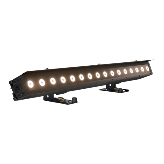
Tunable white led pixbar ip65
Hide thumbs
Also See for PIXBAR G2:
- User manual (288 pages) ,
- User manual (103 pages) ,
- User manual (48 pages)

Related Manuals for Cameo PIXBAR G2


Summary of Contents for Cameo PIXBAR G2
- Page 1 USER´S MANUAL BEDIENUNGSANLEITUNG MANUEL D`UTILISATION MANUAL DE USUARIO INSTRUKCJA OBSŁUGI MANUALE D‘ USO PIXBAR ® TUNABLE WHITE LED PIXBAR IP65 CLPBTWIPG2...
-
Page 2: Table Of Contents
CONTENTS / INHALTSVERZEICHNIS / CONTENU / CONTENIDO / TREŚĆ / CONTENUTO ENGLISH INFORMATION ON THIS USER MANUAL INTENDED USE DEFINITIONS AND SYMBOL EXPLANATIONS SAFETY INSTRUCTIONS NOTES ON PORTABLE OUTDOOR DEVICES PACKAGING CONTENT INTRODUCTION CONNECTIONS, OPERATING AND DISPLAY ELEMENTS OPERATION INSTALLATION FROST FILTER GLARE SHIELD CARE, MAINTENANCE AND REPAIR... - Page 3 OPTIONALES ZUBEHÖR ABMESSUNGEN TECHNISCHE DATEN ERLÄUTERUNGEN ZUR IP-SCHUTZART MINDESTABSTAND ZUR BELEUCHTETEN FLÄCHE MINDESTABSTAND ZU NORMAL ENTFLAMMBAREN MATERIALIEN ENTSORGUNG HERSTELLERERKLÄRUNGEN FRANÇAIS INFORMATIONS SUR CE MANUEL D'UTILISATION UTILISATION PRÉVUE DÉFINITIONS ET EXPLICATION DES PICTOGRAMMES CONSIGNES DE SÉCURITÉ NOTES SUR LES APPAREILS PORTABLES POUR EXTÉRIEUR CONTENU DU CARTON INTRODUCTION CONNECTEURS, UTILISATION ET INDICATEURS...
- Page 4 CONTENTS / INHALTSVERZEICHNIS / CONTENU / CONTENIDO / TREŚĆ / CONTENUTO INDICACIONES PARA EQUIPOS PORTÁTILES DE EXTERIOR ELEMENTOS SUMINISTRADOS INTRODUCCIÓN CONEXIONES, CONTROLES E INDICADORES OPERACIÓN MONTAJE FILTRO FROST PROTECCIÓN ANTIRREFLEJO CUIDADO, MANTENIMIENTO Y REPARACIÓN ACCESORIOS OPCIONALES DIMENSIONES CARACTERÍSTICAS TÉCNICAS EXPLICACIÓN SOBRE LA CLASE DE PROTECCIÓN IP DISTANCIA MÍNIMA A LA SUPERFICIE ILUMINADA DISTANCIA MÍNIMA A MATERIALES NORMALMENTE INFLAMABLES ELIMINACIÓN...
- Page 5 MINIMALNA ODLEGŁOŚĆ OD NORMALNIE ŁATWOPALNYCH MATERIAŁÓW: UTYLIZACJA DEKLARACJE PRODUCENTA ITALIANO INFORMAZIONI SU QUESTO MANUALE D’ISTRUZIONI USO CONFORME SPIEGAZIONE DI TERMINI E SIMBOLI INDICAZIONI SULLA SICUREZZA AVVERTENZE PER DISPOSITIVI PORTATILI PER ESTERNI DOTAZIONE INTRODUZIONE CONNESSIONI, ELEMENTI DI COMANDO E INDICATORI UTILIZZO MONTAGGIO FILTRO FROST PROTEZIONE ANTIRIFLESSO...
-
Page 6: Information On This User Manual
This device has been developed and manufactured to the highest quality standards to ensure many years of trouble-free operation. Please read this user manual carefully to be able to quickly put your new Cameo Light product to optimum use. Further information about Cameo Light is available on our website CAMEOLIGHT.COM. -
Page 7: Safety Instructions
This symbol identifies hazards that can cause electric shock. This symbol identifies hazardous areas or hazardous situations. This symbol indicates hazards caused by hot surfaces. This symbol indicates hazards caused by intense light sources. This symbol indicates a device in which there are no user-replaceable parts. This symbol indicates additional information on the operation of the product. - Page 8 2. Make sure that the voltage and frequency of the mains supply correspond to the values indicated on the device. If the device has a voltage selector switch, do not turn the device on until it has been set correctly. Use only suitable power cables. 3.
- Page 9 CAUTION: 3. The exterior surface of the device can become very hot during regular operation. Ensure that accidental touching of the housing is not possible. Always allow the device to cool sufficiently before removal, maintenance work and charging etc. ATTENTION: 1.
-
Page 10: Notes On Portable Outdoor Devices
High volumes of radio traffic (e.g. powerful wireless LAN networks) Interference Electromagnetic radiation (e.g. LED video screens, dimmers) All range specifications refer to free-field line-of-sight applications without interfer- ence! The operation of radio transmission systems is subject to official regulations. These may vary from region to region and must be checked by the operator before use (e.g. -
Page 11: Packaging Content
The LED Bar supports the RDM standard (Remote Device Management). Remote device manage- ment allows the user to monitor the status and configuration of RDM devices using an RDM-ca- pable controller, such as the optionally available Cameo UNICON (item number CLIREMOTE). The Cameo UNICON also allows access to the entire fixture menu. -
Page 12: Connections, Operating And Display Elements
IP65 mains output socket with rubber sealing cap (TRUE1 compatible). Enables power supply to other CAMEO lights. Ensure that the total current consumption of all connected devices does not exceed the value specified on the device in amperes (A) (when not in use, always close the rubber sealing cap). - Page 13 ENTER – Press ENTER to access the menu level in order to make value or status changes, and to access one of the sub-menus. Confirm value or status changes by pressing ENTER. PLEASE NOTE: • Before navigating the menu, make sure that the control panel is dry and clean so that its functionality is not impaired.
-
Page 14: Operation
• As soon as the fixture is correctly connected to the power supply, the following messages are displayed in succession: “Update wait ...” (for service purposes only), “Welcome to Cameo”, the model name and the software version. After this process, the light is ready for operation and the previously activated operating mode is launched. - Page 15 DMX modes with DMX delay channel The DMX Delay function is a simple way to create a running light effect with a large number of identical fixtures that are running the same software version, which would otherwise require a suitable DMX controller and extensive programming. All the lights used (same model, same soft- ware version) are set to the same DMX mode with DMX delay channel and controlled via the same DMX start address.
- Page 16 In the stand-alone modes Auto Program and Play Loop, you can set a delay for slave units to delay the output of the control signal. Starting from the main screen, press MENU to enter the main menu. Now select Stand Alone, confirm, select Master/Alone and confirm again.
- Page 17 Starting from the main screen, press MENU to enter the main menu. Use UP and DOWN to select Stand Alone, confirm the selection, then select CCT and confirm again with ENTER. Now select the menu item you want to edit, confirm the selection and make the settings as desired. Confirm each entry.
- Page 18 EDIT LOOP The brightness, step duration and fade time can be set independently for all eight loops. Starting from the main screen, press MENU to enter the main menu. Using UP and DOWN, select Stand Alone, confirm with ENTER, then select Edit Loop and confirm again. Now select the desired loop for editing and confirm.
- Page 19 extensive programming. Connect the slave and master units (same model, same software version) using a DMX cable or via W-DMX ™ 0 - 24 Set slave group for signal delay XLR (permanently active) Activate W-DMX module Deactivate W-DMX module Disconnect all connections and place in pairing standby mode Assign the fixtures to one of up to 24 groups (plus Group 0) according to preference, whereby se-...
- Page 20 Pair with W-DMX devices. W-DMX must be enabled on all devices, and the pairing with a transmitter must be reset (Receive Reset). Wireless Send incoming signal to XLR connector settings Use the XLR input signal in case the W-DMX signal is lost. No connection between W-DMX signal and XLR connectors Rotate display by 180°...
- Page 21 Simulates the colour drift when dim- ming a halogen light. When dimming the light, the colour temperature changes Dimming automatically to increasingly warm white behaviour tones and amber (and vice versa). and PWM Function disabled frequency Constant brightness at all CCT values Maximum brightness at all CCT values Amber, warm white and cold white with a maximum value of 255...
- Page 22 Factory Reset to factory setting Reset to user A values (save user values: Settings -> Store User A Default) Load Default Reset to user B values (save user values: Settings -> Store User B Default) Reset to user C values (save user values: Settings -> Store User C Default) Cancel operation...
-
Page 23: Installation
INSTALLATION DANGER: Installation, especially overhead installation, requires extensive experi- ence, relevant & up-to-date expertise and competence, including the calculation of working load limits, the installation material used and regular safety checks of all installation materials and fixtures! If you do not have these qualifications, do not at- tempt to carry out an installation yourself, but use the help of appropriately qualified specialist companies! There is a risk that devices that are incorrectly mounted and secured may come loose and fall down. - Page 24 USE SPIN16 TV SPIGOT FOR MOUNTING The mounting feet of the PIXBAR G2 have 16 mm TV spigots that can be extended and retracted ® without tools. To unfold a TV spigot, pull the spring-loaded locking bolt out of the locking hole in the direction of the arrow (1), fold the TV spigot forwards and let the locking bolt engage in the locking hole offset by 90°...
- Page 25 VERTICAL HANGING MOUNTING ON A TRUSS For vertical hanging mounting, up to three PIXBAR G2 may be connected to each other. ® The following optionally available products must be used for this: A suitable truss clamp with sufficient load-bearing capacity for the total load (e.g. half coupler).
-
Page 26: Frost Filter
VERTICAL FLOOR MOUNTING For vertical floor mounting, a maximum of two PIXBAR G2 may be connected to each other. ® The following optionally available products must be used for this: One connector (item number CLPBG- 2STACKKIT). One stop set (article number CLPBG2VERTI- MOUNT). -
Page 27: Glare Shield
GLARE SHIELD A glare shield is included with the PIXBAR G2. On both sides of the PIXBAR G2 there are three ® ® threads on the top edge of the housing (1). Mount the glare shield on the desired side of the PIXBAR G2 using the three knurled screws (2). -
Page 28: Optional Accessories
2. Air inlets and outlets must be regularly cleaned of dust and dirt. If compressed air is used, make sure that damage to the device is prevented (e.g. fans must be blocked in this case, as they could otherwise over-rev.). 3. -
Page 29: Dimensions
DIMENSIONS (mm) 1000 1000 1018 98,5... -
Page 30: Technical Data
TECHNICAL DATA... -
Page 31: Explanation Of Ip Protection Class
EXPLANATION OF IP PROTECTION CLASS 1. An IP rating only reflects protection from solid objects and water. It does not describe general weather resistance, such as protection from UV radiation and temperature, etc. 2. The first identification digit indicates protection from dust, solid objects and contact: IP2X Protected against solid foreign objects ≥... -
Page 32: Minimum Distance To Illuminated Surface
IP4X Protected against solid foreign objects ≥ 1.0 mm in diameter IP5X Protected against dust in harmful quantities and completely protected against contact IP6X Dust-tight and completely protected against contact 3. The second identification digit indicates protection from water: IPX0 No protection IPX1 Protection against dripping water... -
Page 33: Manufacturer's Declarations
DEVICE: 1. This device is subject to the European Directive on Waste Electrical and Electronic Equipment as amended. WEEE Directive Waste Electrical and Electronic Equip- ment. Electronic devices do not belong in household waste. The old device must be disposed of via an approved disposal company or a municipal disposal facility. Please observe the applicable regulations in your country! 2. -
Page 34: Deutsch
Dieses Gerät wurde unter hohen Qualitätsanforderungen entwickelt und gefertigt, um viele Jahre einen reibungslosen Betrieb zu gewährleisten. Bitte lesen Sie diese Bedienungsanleitung sorgfäl- tig, damit Sie Ihr neues Produkt von Cameo Light schnell und optimal einsetzen können. Weitere Informationen über Cameo Light erhalten Sie auf unserer Website CAMEOLIGHT.COM. -
Page 35: Sicherheitshinweise
Dieses Symbol kennzeichnet Gefahren, die einen elektrischen Schlag verursachen können. Dieses Symbol kennzeichnet Gefahrenstellen oder gefährliche Situationen. Dieses Symbol kennzeichnet Gefahren durch heiße Oberflächen. Dieses Symbol kennzeichnet Gefahren durch intensive Lichtquellen. Dieses Symbol kennzeichnet ein Gerät, in dem sich keine vom Benutzer austauschba- ren Teile befinden. - Page 36 ACHTUNG: 1. Nehmen Sie das Gerät nicht in Betrieb, wenn es starken Temperaturschwankungen ausgesetzt war (beispielsweise nach dem Transport). Feuchtigkeit und Kondensat könnten das Gerät beschädigen. Schalten Sie das Gerät erst ein, wenn es Umge- bungstemperatur erreicht hat. 2. Stellen Sie sicher, dass die Spannung und die Frequenz des Stromnetzes mit den auf dem Gerät angegebenen Werten übereinstimmen.
- Page 37 5. Beachten Sie unbedingt den angegebenen Mindestabstand zu normal entflammba- ren Materialien! Sofern dieser nicht explizit ausgewiesen ist, beträgt der Mindest- abstand 0,3 m. 6. Beachten Sie unbedingt den auf dem Gerät abzulesenden Mindestabstand zur beleuchteten Fläche! VORSICHT: 1. Bei beweglichen Bauteilen wie Montagebügeln, oder sonstigen beweglichen Bau- teilen besteht die Möglichkeit sich zu klemmen.
- Page 38 VORSICHT! WICHTIGE HINWEISE IN BEZUG AUF LICHT-PRODUKTE! 1. Blicken Sie niemals, auch nicht kurzzeitig, direkt in die Lichtquelle. 2. Blicken Sie niemals mit optischen Geräten wie Vergrößerungsgläsern in die Lichtquelle. 3. Stroboskopeffekte können bei empfindlichen Menschen epileptische Anfälle auslösen! 4. In diesen Leuchten sind fest installierte Leuchtmittel verbaut, welche nicht durch den Benutzer zu tauschen sind.
-
Page 39: Hinweise Für Ortsveränderliche Outdoor-Geräte
SIGNALÜBERTRAGUNG PER W-DMX WARNUNG: Generell darf kabellose DMX-Übertragung nicht für Anwendungen mit sicherheitsrelevanten Faktoren genutzt werden, die im Falle eines Versagens Perso- nen- oder Sachschäden zur Folge haben können. Dies gilt im Speziellen für bewegte Szenen- oder Traversenstrukturen, für DMX-gesteu- erte Motoren/Hebezeuge oder Hebevorrichtungen zum Betreiben von DMX-betriebenen Bühnenliften, Hydrauliksystemen oder vergleichbaren beweglichen Komponenten. -
Page 40: Anschlüsse, Bedien- Und Anzeigeelemente
Die LED Bar verfügt über den RDM-Standard (Remote Device Management). Diese Gerätefern- verwaltung ermöglicht die Statusabfrage und Konfiguration von RDM-Endgeräten über einen RDM-fähigen Controller, wie den optional erhältlichen Cameo UNICON (Artikelnummer CLIREMOTE). Der Cameo UNICON ermöglicht darüber hinaus den Zugriff auf das gesamte Scheinwerfermenü. ANSCHLÜSSE, BEDIEN- UND ANZEIGEELEMENTE POWER IN IP65 Netzeingangsbuchse mit Gummidichtkappe (TRUE1 kompatibel). - Page 41 DMX IN Männliche IP65 5-Pol XLR-Buchse zum Anschließen eines DMX-Kontrollgeräts (z.B. DMX-Pult, bei Nichtgebrauch stets mit der Gummidichtkappe verschließen). DMX OUT Weibliche IP65 5-Pol XLR-Buchse zum Weiterleiten des DMX-Steuersignals (bei Nichtgebrauch stets mit der Gummidichtkappe verschließen). OLED-DISPLAY Das OLED-Display zeigt die aktuell aktivierte Betriebsart bzw. die aktuelle DMX-Adresse (Hauptan- zeige), die Menüpunkte im Menü...
-
Page 42: Bedienung
ANMERKUNGEN • Sobald der Scheinwerfer korrekt am Stromnetz angeschlossen ist, wird während des Start- vorgangs nacheinander „Update wait..“ (nur für Service-Zwecke), „Welcome to Cameo“, die Modellbezeichnung und die Softwareversion im Display angezeigt. Nach diesem Vorgang ist der Scheinwerfer betriebsbereit und die Betriebsart, die zuvor aktiviert war, wird gestartet. - Page 43 DMX-Betriebsarten mit DMX-Delay-Kanal Mit Hilfe der Funktion DMX-Delay kann auf einfache Weise mit einer beliebig großen Anzahl Scheinwerfern des gleichen Modells und Softwarestands ein Lauflichteffekt realisiert werden, der sonst nur mit einem geeigneten DMX-Controller und aufwändiger Programmierung erreicht werden könnte. Dabei werden alle einbezogenen Scheinwerfer (gleiche Modelle, gleicher Soft- warestand) auf die gleiche DMX-Betriebsart mit DMX-Delay-Kanal eingestellt und auf der gleichen DMX-Startadresse angesteuert.
- Page 44 Setup-Beispiel: STAND-ALONE-MENÜ MASTER / ALONE In den Stand-Alone-Betriebsarten Direct LED, CCT und Play Loop kann das Steuersignal der entsprechenden Betriebsart via XLR (DMX OUT) und W-DMX an Slave-Einheiten ausgegeben ™ werden: Stand Alone -> Master/Alone -> Master Ist die Ausgabe des Steuersignals nicht gewünscht, kann die Ausgabe deaktiviert werden: Stand Alone ->...
- Page 45 STAND-ALONE-BETRIEBSART DIRECT LED Die Stand-Alone Betriebsart Direct LED ermöglicht es, ähnlich wie mit einem DMX-Steuergerät, Dimmer, Amber, Warm White und Cold White direkt am Gerät einzustellen. Somit kann eine indivi- duelle Szene erstellt werden, ohne einen zusätzlichen DMX-Controller zu benötigen. Ausgehend von der Hauptanzeige gelangen Sie durch Drücken auf MENU in das Hauptmenü.
- Page 46 TIMER-FUNKTION Die Timer-Funktion ermöglicht die zeitgesteuerte Kontrolle der Stand-Alone-Betriebsarten Direct LED und CCT in der Art, dass die Einblendzeit (Fade In) von 0 bis 60 Minuten, die Haltezeit (Dwell Time) von 1 bis 24 Stunden und die Ausblendzeit (Fade Out) von 0 bis 60 Minuten eingestellt wer- den kann.
- Page 47 Daraufhin gelangen Sie in das Untermenü zum Einstellen der Untermenüpunkte (siehe Tabelle). Die Einstellungen werden für jeden Loop separat vorgenommen und bleiben auch nach einem Neustart des Geräts erhalten. Step 1 - 8 Auswahl des Schritts t-Step 0s - 10s = 0,1s steps Einstellen der Schrittdauer für den t-Step 10s - 1min = 1s steps...
- Page 48 Slave-Gruppe für Signal-Delay Group 0 - 24 einstellen XLR (permanent aktiv) W-DMX Modul aktivieren Receive W-DMX Modul deaktivieren Wire- Mode Alle Verbindungen trennen less Unlink und in Koppelbereitschaft versetzen Ordnen Sie die Scheinwerfer nach Wunsch einer von bis zu 24 Gruppen (plus Gruppe 0) zu, wobei auch mehrere Scheinwerfer einer Gruppe zugeordnet werden können.
- Page 49 Eingehendes Signal an XLR-Anschluss Send to XLR senden Verwenden des eingehenden Sig- Wire- Wireless- Signal Backup by nals vom XLR-Anschluss, wenn das less Einstellungen Routing W-DMX-Signal verloren geht. Keine Verbindung zwischen W-DMX-Sig- Receive only nal und XLR-Anschlüssen Drehung der Display-Anzeige um 180° Reverse (z.B.
- Page 50 Simuliert die Farbdrift beim Dimmen eines Halogenscheinwerfers. Beim Herunterdimmen des Scheinwerfers Dim to Warm verändert sich die Farbtemperatur Redshift Dimmver- automatisch zunehmend zu wärmeren Dim- halten und Weißtönen und Amber (und umgekehrt) PWM-Fre- Funktion deaktiviert quenz Konstante Helligkeit bei allen CCT-Wer- Constant CCT Fade Brightness...
- Page 51 Informationen zu den Untermenüpunkten im Service-Menü und den entsprechenden Optionen finden Sie in untenstehender Tabelle (Auswahl mit UP und DOWN, bestätigen mit ENTER, Wert bzw. Status ändern mit UP und DOWN, bestätigen mit ENTER). Factory Zurücksetzen auf Werkseinstellung Zurücksetzen auf User A Werte (User Werte speichern: Settings -> User A Store Default) Load Default...
-
Page 52: Montage
MONTAGE GEFAHR: Montage, insbesondere Überkopfmontage, erfordert umfassende Er- fahrung, einschlägige & aktuelle Fachkenntnis und Kompetenz, einschließlich der Berechnung der Grenzwerte für die Arbeitslast, des verwendeten Installationsma- terials und der regelmäßigen Sicherheitsüberprüfung aller Installationsmaterialien und Scheinwerfer! Wenn Sie diese Qualifikationen nicht haben, versuchen Sie nicht, eine Installation selbst durchzuführen, sondern nutzen Sie die Hilfe von entsprech- end qualifizierten Fachunternehmen! Es besteht die Gefahr, dass sich nicht korrekt montierte und gesicherte Geräte lösen und herabfallen. - Page 53 talen Überkopfmontage mehrerer gedockter PIXBAR G2 muss jede einzelne PixBa PIXBAR ® ® mit den Montagefüßen separat an der Traverse befestigt und mit einem geeigneten Sicherungsseil gesichert werden. SPIN16 TV-ZAPFEN FÜR DIE MONTAGE VERWENDEN Die Montagefüße der PIXBAR G2 verfügen über werkzeuglos aus- und einklappbare 16 mm ®...
- Page 54 VERTIKAL HÄNGENDE MONTAGE AN EINER TRAVERSE Für die vertikal hängende Montage dürfen bis zu drei PIXBAR G2 miteinander verbunden ® werden. Hierfür müssen folgende optional erhältliche Produkte verwendet werden: Eine geeignete Traversenklemme mit ausrei- chender Tragkraft für die Gesamtlast (z.B. Halfcoupler).
-
Page 55: Frostfilter
Oberfläche beschädigt wird. FROSTFILTER Ein Standard Frostfilter ist im Lieferumfang der PixBar G2 enthalten. Um den Frostfilter in die dafür vorgesehene Halterung (1) der Bar einzusetzen, öffnen Sie den Schieberiegel an einem Ende der Bar (2, am Griff nach unten schieben). Nachdem Sie den Frostfilter in die Halterung eingesetzt... -
Page 56: Blendschutz
BLENDSCHUTZ Ein Blendschutz ist im Lieferumfang der PixBar G2 enthalten. Auf beiden Seiten der PixBar G2 befinden sich jeweils drei Gewinde an der Oberkante des Gehäuses (1). Montieren Sie den Blend- schutz mit Hilfe der drei Rändelschrauben (2) an die gewünschte Seite der PixBar G2. -
Page 57: Optionales Zubehör
hindert werden (z.B. müssen Lüfter für diesen Fall blockiert werden, da sie sonst überdrehen könnten). 3. Leitungen und Steckkontakte sind regelmäßig zu reinigen und von Staub und Schmutz zu befreien. 4. Es dürfen generell keine Reinigungsmittel oder Mittel mit schleifender Wirkung zur Pflege verwendet werden, andernfalls ist mit Beeinträchtigung der Oberflächenbeschaffenheit zu rechnen. -
Page 58: Abmessungen
ABMESSUNGEN (mm) 1000 1000 1018 98,5... -
Page 59: Technische Daten
TECHNISCHE DATEN Artikelnummer CLPBTWIPG2 Produktkategorie Statische LED-Lampe LED-Leiste Lichtquelle 16 x 10 W WW-CW-A LEDs Spitzenwert des 4200 lm @ Full On; A: 700 lm; CW: 2000 lm; WW: 2200 lm Lichtstroms (kalt) Linse/Optik 16 x 30 mm Acrylglas PWM-Frequenz 650 Hz;... - Page 60 RDM-Funktionen Cameo Standard-RDM-Funktionen Stand-Alone Direkte LED; CCT; Wiedergabeschleife; Timer; Slave Drahtlos: Status; Signal-Routing; Verknüpfung; Betriebsmodus. Anzeige: Umgekehrt; Autolock; Aus-Timer. Dimmer: Kurve; PWM; Reaktion. Signalfe- Systemeinstel- hler: Halten; Letzter Stand-Alone-Modus; Verblassen zu Schwarz; Szene 1; lungen Voll. Pixel-Mirroring: Aus; Horizontal; Vertikal; Horizontal & Vertikal. Standard speichern als: Benutzer A;...
-
Page 61: Erläuterungen Zur Ip-Schutzart
ERLÄUTERUNGEN ZUR IP-SCHUTZART 1. Eine IP-Schutzart gibt ausschließlich den Schutz gegen feste Gegenstände, sowie Wasser wie- der. Sie beschreibt keine allgemeine Witterungsbeständigkeit, wie beispielsweise Schutz gegen UV-Strahlung und Temperatureinflüsse etc.. 2. Die erste Kennziffer bezeichnet den Schutz gegen Staub, feste Gegenstände und Berührung: IP2X Geschützt gegen feste Fremdkörper mit Durchmesser ≥... -
Page 62: Entsorgung
ENTSORGUNG VERPACKUNG: 1. Verpackungen können über die üblichen Entsorgungswege dem Wertstoffkreislauf zugeführt werden. 2. Bitte trennen Sie die Verpackung entsprechend der Entsorgungsgesetze und Wert- stoffverordnungen in Ihrem Land. GERÄT: 1. Dieses Gerät unterliegt der europäischen Richtlinie für Elektro- und Elektronik-Alt- geräte in der jeweils geltenden aktuellen Fassung. - Page 63 CE-Konformitätserklärung Konformitätserklärungen für Produkte, die der LVD, EMC, RoHS-Richtlinie unterliegen, können unter info@adamhall.com angefragt werden. Konformitätserklärungen für Produkte, die der RED-Richtlinie unterliegen, können unter www. adamhall.com/compliance/ heruntergeladen werden. Druckfehler und Irrtümer, sowie technische oder sonstige Änderungen sind vorbehalten!
-
Page 64: Français
Veuillez lire attentivement ce manuel d'utilisation afin de pouvoir utiliser rapidement et de manière optimale votre nouveau produit Cameo Light. De plus amples informations sur Cameo Light sont disponibles sur notre site web CAMEOLIGHT.COM. -
Page 65: Consignes De Sécurité
Ce pictogramme identifie les dangers qui peuvent causer un choc électrique. Ce pictogramme identifie les zones ou les situations dangereuses. Ce pictogramme indique les dangers occasionnés par les surfaces portées à haute température. Ce pictogramme indique les dangers occasionnés par des sources lumineuses intenses. - Page 66 L'humidité et la condensation internes peuvent endommager l'appareil. Ne mettez l'appareil en marche que lorsqu'il a atteint la température ambiante. 2. Assurez-vous que la tension et la fréquence du secteur correspondent aux valeurs indiquées sur l'appareil. Si l'appareil est équipé d'un sélecteur de tension, ne le mettez pas en marche tant qu'il n'a pas été...
- Page 67 MISE EN GARDE : 1. Les éléments mobiles, tels que les supports de montage, présentent un risque de coincement. 2. Dans le cas d'appareils comportant des composants motorisés, il existe un risque de blessure dû au mouvement de l'appareil. Un mouvement brusque de l'appareil peut provoquer des réactions de choc.
- Page 68 4. Ces unités d'éclairage sont dotées de lampes installées en permanence. L'utilisa- teur ne peut pas les remplacer. En cas de panne, veuillez contacter votre partenaire de distribution. TRANSMISSION DE SIGNAUX PAR RADIO (PAR EXEMPLE, W-DMX OU SYSTÈMES AUDIO SANS FIL) : La qualité...
-
Page 69: Notes Sur Les Appareils Portables Pour Extérieur
En outre, la transmission DMX sans fil ne doit pas être utilisée pour déclencher des dispositifs générateurs de flammes ou pyrotechniques, des effets à explosion ou pour contrôler des effets de gaz ou de liquides. Ces dispositifs peuvent être des canons à CO2, des canons à... -
Page 70: Connecteurs, Utilisation Et Indicateurs
à distance permet à l'utilisateur de contrôler l'état et la configuration des appareils RDM à l'aide d'un contrôleur compatible RDM, tel que le Cameo UNICON disponible en option (numéro d'article CLIREMOTE). Le Cameo UNICON permet également d'accéder à l'ensemble du menu de la barre LED. - Page 71 AFFICHEUR OLED L'afficheur OLED affiche le mode en cours (affichage principal), les éléments disponibles en sélection dans le menu et la valeur numérique ou l'état de fonctionnement de certains éléments du menu. COMMANDES TACTILES MENU – Appuyez sur MENU pour accéder au menu principal. Appuyez à nouveau sur ou à plu- sieurs reprises pour revenir à...
-
Page 72: Utilisation
• Dès que la barre LED est correctement raccordée au secteur, les messages suivants s'affichent successivement : "Update wait (Attente de mise à jour) ..." (service uniquement), "Welcome to Cameo", puis le nom du modèle et la version du logiciel. La barre LED est ensuite prête à fonctionner, dans le dernier mode activé avant extinction. - Page 73 DMX et du groupe (groupe 0 - 24) sont marqués d'un "D". Vous trouverez les tableaux DMX avec l'affectation des canaux dans la section CONTRÔLE DMX de ce manuel d'utilisation. Modes DMX avec canal de retard DMX La fonction DMX Delay est un moyen simple de créer un effet de lumière en mouvement avec un grand nombre de projecteurs identiques fonctionnant avec la même version du logiciel : effet qui nécessiterait sinon un contrôleur DMX approprié...
- Page 74 Exemple de configuration : MODE AUTONOME MENU MASTER / ALONE Dans les modes de fonctionnement autonomes Direct LED et Play Scene/Loop, le signal de com- mande du mode de fonctionnement correspondant peut être renvoyé vers les projecteurs esclaves via XLR (DMX OUT) et W-DMX : ™...
- Page 75 MODE AUTONOME LED DIRECT Le mode autonome "Direct LED" vous permet de régler le gradateur, l'ambre, le blanc chaud et le blanc froid directement sur l'appareil, comme avec un contrôleur DMX. Vous pouvez ainsi créer une scène personnalisée sans contrôleur DMX supplémentaire. À...
- Page 76 FONCTION TIMER (Minuterie) La fonction Timer permet de contrôler le mode autonome Static par une minuterie : vous pouvez ainsi régler la durée de fade-in de 0 à 60 minutes, la durée de maintien (dwell) de 1 à 24 heures et la durée de fermeture de 0 à 60 minutes. Après l'activation de la fonction Timer, le contrôle par la minuterie prendra effet au prochain démarrage du système.
- Page 77 Sélection du pas Réglage de la durée du pas sélec- tionné Réglage de la durée de fondu pour le pas sélectionné Sélection de la température de couleur ou du blackout pour le pas sélectionné Sélectionnez la température de cou- leur ou le blackout, ou sautez le pas sélectionné...
- Page 78 Affectez les projecteurs à l'un des 24 groupes (plus le groupe 0) selon vos préférences – vous pouvez affecter plusieurs projecteurs à un même groupe. Le numéro de groupe est également le facteur multiplicateur de durée de retard réglée sur le projecteur maître. Exemple de configuration : PARAMÈTRES SYSTÈME (Settings) À...
- Page 79 Rotation de l'affichage de 180° (par ex- emple pour une installation en hauteur) Pas de rotation de l'affichage L'éclairage de l'écran reste allumé en permanence Désactivation de l'éclairage de l'écran Paramètres après environ 20 secondes d'inactivité de l’écran Fonction désactivée Les commandes et l'écran sont ver- rouillés après environ 60 secondes d'inactivité.
- Page 80 Simule la dérive des couleurs lors de la gradation d'un projecteur halogène. Lors de la gradation du projecteur, la température de couleur passe automa- Compor- tiquement à des tons blancs de plus en tement de plus chauds et à l'ambre (et vice versa). gradation et Fonction désactivée fréquence...
- Page 81 MENU SERVICE (Service) À partir de l'écran principal, appuyez sur MENU pour accéder au menu principal. Sélectionnez Service à l'aide des touches UP et DOWN puis confirmez avec ENTER. Vous trouverez dans le tableau ci-dessous des informations sur les éléments des sous-menus du menu de service et les options correspondantes (sélectionner avec UP et DOWN, confirmer avec ENTER, modifier la valeur ou l'état avec UP et DOWN, confirmer avec ENTER).
-
Page 82: Installation
Total xxxx h : xx m Durée de fonctionnement totale Operation xxxx h : xx m Durée d'utilisation xxxx h : xx m Durée de fonctionnement de la lampe Runtime Durée d'utilisation depuis la réinitialisa- Service xxxx h : xx m tion de la durée de fonctionnement en maintenance RDM-UID... - Page 83 tage en oméga disponibles en option (référence CLOMEGABRACKET1). Les pieds de montage peuvent être déplacés sur le boîtier de la PIXBAR G2. Pour ce faire, desserrez la vis centrale des ® cinq vis hexagonales internes (2), déplacez le pied dans la position souhaitée et resserrez la vis. La direction du faisceau peut être réglée à...
- Page 84 MONTAGE EN SUSPENSION VERTICALE SUR UNE STRUCTURE Pour un montage vertical suspendu, vous pou- vez fixer ensemble jusqu'à trois PIXBAR ® Les accessoires suivants, disponibles en option, doivent être utilisés à cet effet : Un étrier de serrage approprié, possédant une capacité de charge suffisante pour la charge totale (par exemple, un de- mi-coupleur) Un support en oméga (référence CLOME-...
-
Page 85: Filtre Frost
MONTAGE VERTICAL AU SOL Pour un montage vertical au sol, vous pouvez relier entre elles jusqu'à deux PIXBAR G2. Les ® accessoires suivants, disponibles en option, doivent être utilisés à cet effet : Une pièce de liaison (référence CLPBG2S- TACKKIT). Un support pour montage vertical (référence CLPBG2VERTIMOUNT). -
Page 86: Écran Anti-Éblouissement
ÉCRAN ANTI-ÉBLOUISSEMENT La PIXBAR G2 est livrée avec un filtre anti-éblouissement. Sur les deux côtés de la PIXBAR ® ® trois filets courent sur le bord supérieur du boîtier. Montez l'écran anti-éblouissement sur le côté souhaité de la PIXBAR G2 à l'aide des trois vis moletées. ®... -
Page 87: Accessoires En Option
2. Les entrées et sorties d'air doivent être régulièrement débarrassées de la poussière et des saletés. Si vous utilisez de l'air comprimé, veillez à ne pas endommager l'appareil (dans ce cas, il faut bloquer les ventilateurs avant d'envoyer l'air comprimé). 3. -
Page 88: Dimensions
DIMENSIONS (mm) 1000 1000 1018 98,5... -
Page 89: Caractéristiques Techniques
CARACTÉRISTIQUES TECHNIQUES Référence CLPBTWIPG2 produit Catégorie de Éclairage LED statique produit Type Barre LED Source lumineu- 16 LED WW-CW-A de puissance 10 W Valeur crête de flux lumineux 4200 lm en plein feu ; A : 700 lm ; CW : 2000 lm ; WW : 2200 lm (froid) Lentille/optique Lentille acrylique 16 x 30 mm... - Page 90 ; Température de couleur d'arrière-plan ; Réglages des ap- pareils ; Groupement ; DMX-Delay (EZ-Chase) ; Gradateur Pixel 1,... Dimmer Pixel 16 ; Pixel : A1, WW1, CW1,... A16, WW16, CW16 Fonctions RDM Fonctions RDM standard Cameo Mode Autonome Direct LED ; CCT ; Play Loop ; Timer ; Slave (Stand Alone) Wireless : State ;...
-
Page 91: Explication De La Classe De Protection Ip
Puissance consommée en 9 W veille : Embases d’alimentation Entrée et sortie : Seetronic IP65 secteur Branchement en cascade (via ren- Jusqu'à 9 projecteurs en 230 V ; jusqu'à 5 projecteurs en 110 V voi Power Link) Distance mini- male par rapport 0,3 m à la surface éclairée Distance mini- male par rapport... -
Page 92: Distance Minimale Par Rapport À La Surface Éclairée
IPX4 Protection contre les projections d’eau sur tous les côtés IPX5 Protection contre les jets d’eau (par une buse) sous tous les angles IPX6 Protection contre les jets d'eau puissants IPX7 Protection contre l’immersion temporaire 4. En outre, certaines mesures spécifiques à l'appareil, telles que couvercles et capuchons d'étan- chéité, sont nécessaires pour atteindre la classe de protection spécifiée (par exemple, placement de capuchons de protection sur les connecteurs inutilisés). -
Page 93: Déclarations Du Fabricant
2. Respectez toutes les lois relatives à l'élimination des déchets en vigueur dans votre pays. 3. En tant que particulier, vous pouvez obtenir des informations sur les possibilités d'élimination respectueuse de l'environnement auprès du vendeur du produit ou des autorités régionales compétentes. DÉCLARATIONS DU FABRICANT GARANTIE DU FABRICANT ET LIMITATION DE RESPONSABILITÉ... -
Page 94: Español
Este equipo está diseñado y fabricado con los estándares de calidad más exigentes, para garan- tizar un correcto funcionamiento durante muchos años. Lea atentamente este manual de usuario para poder aprovechar rápidamente toda la funcionalidad de su nuevo producto de Cameo Light. Más información sobre Cameo Light en la web CAMEOLIGHT.COM. -
Page 95: Instrucciones De Seguridad
Este símbolo indica peligro de descarga eléctrica. Este símbolo identifica las zonas o situaciones peligrosas. Este símbolo indica peligro por superficie a alta temperatura. Este símbolo indica peligro debido a fuente de luz intensa. Este símbolo indica que en el equipo no hay piezas que pueda sustituir el usuario. Este símbolo indica información complementaria sobre el uso del producto. - Page 96 2. Asegúrese de que la tensión y la frecuencia de la red eléctrica coinciden con los valores indicados en el equipo. Si el equipo dispone de un selector de tensión, antes de enchufarlo a la red eléctrica, asegúrese de que el valor seleccionado es correcto.
- Page 97 2. En el caso de los equipos con componentes accionados por motor, existe riesgo de lesiones por el movimiento del equipo. Un movimiento brusco del aparato puede provocar lesiones por impacto. 3. La superficie de la carcasa del equipo puede calentarse mucho durante el funcio- namiento normal.
- Page 98 TRANSMISIÓN DE SEÑALES POR RADIO (COMO W-DMX O SISTEMAS DE AUDIO POR RADIO): La calidad y las prestaciones de las transmisiones de señales inalámbricas suel- en depender de las condiciones ambientales. Por ejemplo, los siguientes factores pueden influir en el alcance y la estabilidad de la señal: Apantallamiento (como muros, estructuras metálicas, agua).
-
Page 99: Indicaciones Para Equipos Portátiles De Exterior
INDICACIONES PARA EQUIPOS PORTÁTILES DE EXTERIOR 1. Operación temporal. En principio, los equipos para eventos están diseñados solo para un uso temporal. 2. El funcionamiento continuo o la instalación permanente, sobre todo en exteriores, pueden perjudicar el funcionamiento, las superficies y las juntas, así como acelerar el desgaste del material. -
Page 100: Conexiones, Controles E Indicadores
Salida eléctrica IP65 con tapa hermética de goma (compatible con TRUE1). Sirve para alimentar otros focos CAMEO. Asegúrese de que el consumo total de todos los equipos conectados no su- pere los amperios especificados del equipo (cuando no se utilice, dejar siempre la tapa cerrada). - Page 101 principal), las opciones del menú y el valor o el modo de funcionamiento dentro de las diferentes opciones de menú. BOTONES TÁCTILES MENU: Pulse MENU para ir al menú principal. Pulse este botón una o varias veces para volver a la pantalla principal.
-
Page 102: Operación
«Update wait.» (solo para mantenimien- to), «Welcome to Cameo», el modelo del equipo y la versión del software. Al terminar el proce- so, el equipo ya está listo para funcionar y se activará el modo de funcionamiento seleccionado previamente. - Page 103 Modos operativos DMX con canal de retardo DMX: Con la función retardo de DMX se puede crear un efecto de luces en movimiento de manera sencilla con cualquier número de focos del mismo modelo y con la misma versión de software, lo que normalmente solo se podría hacer con un controlador DMX adecuado y mucha programación.
- Page 104 MODO AUTÓNOMO. MENÚ MASTER/ALONE En los modos de funcionamiento autónomo Direct LED, CCT y Play Loop, la señal de control del modo de funcionamiento correspondiente puede enviarse a los equipos esclavos por el conector XLR (DMX OUT) y por W-DMX™: Stand Alone > Master/Alone > Master Puede desactivarse la salida de la señal de control si no es necesaria:: Stand Alone ->...
- Page 105 MODO AUTÓNOMO CCT (Correlated Color Temperature) En el modo CCT autónomo, la temperatura de color puede ajustarse en pasos de 100 K desde 1.800 K hasta 6.500 K, además del tono (Tint) y la intensidad (Dimmer). Desde la pantalla principal, pulse MENU para ir al menú principal. Pulse UP y DOWN para selec- cionar la opción de menú...
- Page 106 Desde la pantalla principal, pulse MENU para ir al menú principal. Seleccione Stand Alone, confirme la selección, después seleccione Timer y vuelva a confirmar la selección. Seleccione el valor On en Timer con y confirme. Para modificar los ajustes del control temporal, seleccione Fade In, Dwell Time o Fade Out y confirme la selección.
- Page 107 Selección de la temperatura de color o el oscurecimiento para el paso seleccionado Selección de la temperatura de color o el oscurecimiento o el paso seleccionado MODO ESCLAVO Modo esclavo estándar: Desde la pantalla principal, pulse MENU para entrar en el menú principal.
- Page 108 Ejemplo de configuración: CONFIGURACIÓN (Settings) Desde la pantalla principal, pulse MENU para ir al menú principal. Con los botones UP y DOWN seleccione la opción de menú Settings y confirme con ENTER. Seguidamente se abre el submenú que permite ajustar las opciones de submenú (ver tabla; seleccionar con los botones UP y DOWN y confirmar con ENTER, modificar los valores o el estado con los botones UP y DOWN y confirmar con ENTER).
- Page 109 Función desactivada Los mandos y la pantalla se bloquean al Ajustes de cabo de unos 60 segundos sin ninguna pantalla operación. Desbloquear: Pulse UP y DOWN simultáneamente durante unos 5 segundos Curva de atenuación: La intensidad de la luz aumenta linealmente con el valor Curva de atenuación: La intensidad de la luz se puede ajustar para que varíe poco a niveles bajos de DMX y mucho a...
- Page 110 Ámbar, blanco cálido y blanco frío con un valor máximo de 255 Calibración Calibración individual. Ajuste de inten- del color sidad de ámbar, blanco cálido y blanco frío con valores de 0 a 255 en todos los modos Último modo operativo Se inicia el último modo autónomo Estado op- activado...
- Page 111 Cancelar el proceso Reset Service Timer Reset now Restablecer el tiempo de funcionamiento de servicio Password Solo para mantenimiento INFORMACIÓN DEL SISTEMA (System Info) Desde la pantalla principal, pulse MENU para acceder al menú principal. Pulse UP y DOWN para seleccionar System Info y confirme con ENTER.
-
Page 112: Montaje
MONTAJE PELIGRO: La instalación, y sobre todo el montaje en altura, requiere una amplia experiencia, conocimientos técnicos y actualizados, incluido el cálculo de los valores límite de la carga de trabajo, el material de instalación utilizado y las comproba- ciones de seguridad periódicas de todos los materiales de instalación y focos. Si no está... - Page 113 UTILICE EL ADAPTADOR DE ESPIGA SPIN16 PARA EL MONTAJE Los pies de montaje de la barra PIXBAR G2 tienen adaptador de espigas de 16 mm que pueden ® abrir y cerrarse sin necesidad de ninguna herramienta. Para abrir un adaptador de espiga, tire del perno de bloqueo con resorte para sacarlo del orificio de bloqueo en la dirección indicada (1), doble el adaptador de espiga hacia delante y deje que el perno de bloqueo encaje en el orificio de bloqueo desplazado 90° (2).
- Page 114 MONTAJE SUSPENDIDO VERTICAL EN UN TRUSS Para el montaje suspendido vertical, pueden acoplarse entre sí hasta tres barras PIX- G2. Para ello debe utilizar los siguien- ® tes productos disponibles como accesorios opcionales: Una abrazadera adecuada con capacidad de carga suficiente para el peso total (por ejemplo, una abrazadera simple).
-
Page 115: Filtro Frost
MONTAJE VERTICAL EN EL SUELO Para el montaje vertical en el suelo, pueden conectarse entre sí un máximo de dos barras PIXBAR G2. Para ello debe utilizar los sigui- ® entes productos disponibles como accesorios opcionales: Un conector (ref. CLPBG2STACKKIT). Un accesorio de montaje vertical (ref. -
Page 116: Protección Antirreflejo
PROTECCIÓN ANTIRREFLEJO Con la barra PIXBAR G2 se suministra un protector antirreflejo. En el borde superior de la carca- ® sa y a ambos lados de la barra PIXBAR G2 hay tres roscas (1). Monte la pantalla antirreflejo en el ® lado deseado de la PIXBAR G2 utilizando los tres tornillos moleteados (2). -
Page 117: Accesorios Opcionales
2. Las entradas y salidas de aire deben limpiarse regularmente para eliminar el polvo y la suciedad. Si se utiliza aire comprimido, hay que tener cuidado para evitar que se dañe la unidad (por ejem- plo, los ventiladores deben estar tapados, ya que de lo contrario podrían girar excesivamente). 3. -
Page 118: Dimensiones
DIMENSIONES (mm) 1000 1000 1018 98,5... -
Page 119: Características Técnicas
CARACTERÍSTICAS TÉCNICAS Referencia del CLPBTWIPG2 producto Categoría de Luz LED estática producto Tipo Barra LED Fuente de luz 16 LED WW-CW-A de 10 W Flujo luminoso 4.200 lm a plena potencia. A: 700 lm. CW: 2.000 lm. WW: 2.200 lm (pico, en frío) Lente/óptica Lente acrílica de 16 × 30 mm Frecuencia PWM 650 Hz, 1.530 Hz, 3.600 Hz, 12.000 Hz, 18.900 Hz, 25.000 Hz Resolución del 8/16 bits... - Page 120 CW, Background CW fine, Background Color Temperature, Device Settings, Grouping, DMX-Delay (EZ-Chase), Dimmer Pixel 1- Dimmer Pixel 16, Pixel: A1, WW1, CW1,… A16, WW16, CW16 Funciones RDM Funciones RDM estándar de Cameo Autónomo Direct LED, CCT, Play Loop, Timer, Slave Wireless: State, Signal Routing, Linking, Operation Mode. Display: Reverse, Ajustes del Autolock, Off Timer.
-
Page 121: Explicación Sobre La Clase De Protección Ip
Dimensiones 1.018 mm (1.000 mm cuando los equipos están acoplados) (an. × al. × f.) × 206 mm × 178 mm Peso 12 kg UID de RDM 0x08A4004E 0000-FFFF EXPLICACIÓN SOBRE LA CLASE DE PROTECCIÓN IP 1. La clase de protección IP representa exclusivamente la protección contra objetos sólidos, así como contra el agua. No representa una resistencia general a la intemperie, como la protección contra la radiación UV y los efectos de la temperatura, etc. -
Page 122: Distancia Mínima A Materiales Normalmente Inflamables
DISTANCIA MÍNIMA A MATERIALES NORMALMENTE INFLAMABLES Este símbolo con información de distancia en metros (m) indica la distancia mínima del equipo con respecto a materiales normalmente inflamables. En este 0,5 m ejemplo, la distancia es de 0,5 m. Consulte los datos técnicos de este manual para conocer el valor válido para este equipo. - Page 123 RoHS (2011/65/UE) Directiva RED (2014/53/UE) Declaración de conformidad CE Las declaraciones de conformidad para productos sujetos a las directivas de baja tensión, EMC y RoHS pueden solicitarse a info@adamhall.com Las declaraciones de conformidad de los productos sujetos a la directiva RED pueden descar- garse desde www.adamhall.com/compliance/ Este documento puede estar sujeto a errores tipográficos o de imprenta, así...
-
Page 124: Polski
Urządzenie to zostało opracowane i wyprodukowane zgodnie z najwyższymi standardami jakości, aby zapewnić wiele lat bezawaryjnej pracy. Proszę uważnie przeczytać niniejszą instrukcję obsłu- gi, aby móc szybko optymalnie wykorzystać swój nowy produkt Cameo Light. Więcej informacji na temat Cameo Light znajdą Państwo na naszej stronie internetowej CAMEOLIGHT.COM. -
Page 125: Instrukcje Bezpieczeństwa
Ten symbol wskazuje na zagrożenia, które mogą spowodować porażenie prądem. Ten symbol oznacza niebezpieczne obszary lub niebezpieczne sytuacje. Ten symbol oznacza zagrożenia spowodowane gorącymi powierzchniami. Ten symbol oznacza zagrożenia powodowane przez intensywne źródła światła. Ten symbol oznacza urządzenie, w którym nie ma części wymienianych przez użytkownika. Ten symbol oznacza dodatkowe informacje na temat działania produktu. - Page 126 UWAGA: 1. Nie należy używać urządzenia, jeśli było ono narażone na duże wahania temperatu- ry (na przykład po transporcie). Wilgoć i kondensacja mogą uszkodzić urządzenie. Urządzenie należy włączyć dopiero po osiągnięciu temperatury otoczenia. 2. Proszę upewnić się, że napięcie i częstotliwość sieci zasilającej odpowiadają wartościom podanym na urządzeniu.
- Page 127 5. Proszę zawsze przestrzegać podanej minimalnej odległości od normalnie łatwopalnych materiałów! Jeśli nie jest to wyraźnie określone, minimalna odległość wynosi 0,3 m. 6. Proszę zawsze przestrzegać minimalnej odległości od oświetlanej powierzchni podanej na urządzeniu! PRZESTROGA! 1. Ruchome elementy, takie jak wsporniki montażowe, stwarzają ryzyko zakleszczenia. 2.
- Page 128 PRZESTROGA! WAŻNE INFORMACJE DOTYCZĄCE PRODUKTÓW OŚWIETLENIOWYCH! 1.Nigdy nie należy patrzeć bezpośrednio w wiązkę światła, nawet przez krótki czas. 2. Nigdy nie należy patrzeć w wiązkę światła za pomocą urządzeń optycznych, takich jak szkło powiększające. 3. Efekty stroboskopowe mogą powodować napady padaczkowe u podatnych osób! 4.
-
Page 129: Uwagi Dotyczące Przenośnych Urządzeń Do Zastosowań Zewnętrznych
TRANSMISJA PRZEZ W-DMX PRZESTROGA: Ogólnie rzecz biorąc, bezprzewodowa transmisja DMX nie może być używana do zastosowań związanych z czynnikami bezpieczeństwa, które mogą skut- kować obrażeniami ciała lub uszkodzeniem mienia w przypadku awarii. Dotyczy to w szczególności ruchomych konstrukcji scen lub trawersów, silników/pod- nośników sterowanych przez DMX lub urządzeń... -
Page 130: Przyłącza, Elementy Obsługi I Wskaźniki
POWER OUT Gniazdo wyjściowe IP65 z gumową zaślepką (kompatybilne z TRUE1). Umożliwia zasilanie innych reflektorów CAMEO. Upewnić się, że całkowity pobór prądu przez wszystkie podłączone urzą- dzenia nie przekracza wartości podanej na urządzeniu w amperach (A) (gdy urządzenie nie jest... - Page 131 DMX IN Męskie 5-pinowe gniazdo XLR IP65 do podłączenia urządzenia sterującego DMX (np. konsoli DMX; gdy nie jest używane, należy zawsze zamykać gumową zaślepką). DMX OUT Żeńskie IP65 5-pinowe gniazdo XLR do przesyłania sygnału sterującego DMX (gdy nie jest używa- ne, należy zawsze zamykać...
-
Page 132: Obsługa
UWAGI • Gdy tylko reflektor zostanie prawidłowo podłączony do zasilania, wyświetlane są kolejno na- stępujące komunikaty: "Update wait ..." (tylko do celów serwisowych), "Welcome to Cameo", nazwa modelu i wersja oprogramowania. Po zakończeniu tego procesu reflektor jest gotowy do pracy i uruchamiany jest wcześniej aktywowany tryb pracy. - Page 133 Tryby DMX z kanałem opóźnienia DMX Funkcja opóźnienia DMX jest prostym sposobem na stworzenie efektu działającego światła z dużą liczbą identycznych reflektorów, które działają z tą samą wersją oprogramowania, co w przeciw- nym razie wymagałoby odpowiedniego sterownika DMX i obszernego programowania. Wszystkie używane reflektory (ten sam model, ta sama wersja oprogramowania) są...
- Page 134 Przykład konfiguracji: TRYB STAND-ALONE - MASTER / ALONE W samodzielnych trybach pracy Direct LED, CCT i Play Loop, sygnał sterujący odpowiedniego trybu może być wysyłany do urządzeń podrzędnych przez XLR (DMX OUT) i W-DMX™: Stand Alone -> Master/Alone -> Master Jeśli nie chcą...
- Page 135 STAND-ALONE-BEZPOŚREDNI TRYB AUTONOMICZNY LED Samodzielny tryb "Direct LED" umożliwia ustawienie ściemniacza, oraz kolorów amber, ciepłej bieli i zimnej bieli bezpośrednio na urządzeniu, podobnie jak w przypadku jednostki sterującej DMX. Umożliwia to tworzenie niestandardowych scen bez dodatkowego sterownika DMX. Zaczynając od ekranu głównego, proszę nacisnąć MENU, aby wejść do menu głównego. Proszę zastosować...
- Page 136 FUNKCJA TIMERA Funkcja timera umożliwia sterowanie statycznym trybem autonomicznym za pomocą timera; czas wygaszania można ustawić w zakresie od 0 do 60 minut, czas oczekiwania od 1 do 24 godzin, a czas wygaszania od 0 do 60 minut. Po aktywacji funkcji timera, sterowanie timerem zacznie działać...
- Page 137 Wybór kroku Ustawienie czasu trwania kroku dla wybranego kroku Ustawianie czasu zanikania dla wybranego kroku Wybór temperatury barwowej lub zaciemnienia dla wybranego kroku Proszę wybrać temperaturę barwową, zaciemnienie lub pominąć wybrany krok TRYB SLAVE Tryb standard slave: Zaczynając od ekranu głównego, proszę nacisnąć MENU, aby wejść do menu głównego.
- Page 138 Przypisać reflektory do jednej z maksymalnie 24 grup (plus grupa 0) zgodnie z preferencjami, przy czym do jednej grupy można przypisać kilka reflektorów. Numer grupy jest również współczynni- kiem, przez który mnożony jest czas opóźnienia ustawiony w urządzeniu głównym. Przykład konfiguracji: USTAWIENIA SYSTEMOWE (Settings) Zaczynając od ekranu głównego, proszę...
- Page 139 Obrót wyświetlacza o 180° (np. w przypadku montażu nad głową) Brak rotacji wyświetlacza Podświetlenie wyświetlacza włączone na stałe Dezaktywacja podświetlenia wyświetlac- Ustawienia za po ok. 20 sekundach bezczynności wyświetlacza Funkcja wyłączona Elementy sterujące i wyświetlacz zostaną zablokowane po ok. 60 sekundach przy braku jakiejkolwiek obsługi.
- Page 140 Zachowanie Stała jasność przy wszystkich wartości- podczas ach CCT ściemniania i Maksymalna jasność przy wszystkich częstotliwość wartościach CCT Bursztynowy, ciepły biały i zimny biały z maksymalną wartością 255 Kalibracja Kalibracja niestandardowa. Ustawienie kolorów jasności w trybie krzyżowym bursztynu, ciepłej bieli i zimnej bieli z wartościami od 0 do 255 Zachowywane jest ostatnie polecenie Stan oper-...
- Page 141 Factory Reset do ustawień fabrycznych Reset do wartości Użytkownika A User A (Zapisywanie wartości użytkownika: Settings -> Store Default) Load Default Reset do wartości Użytkownika B User B (Zapisywanie wartości użytkownika: Settings -> Store Default) Reset do wartości Użytkownika C User C (Zapisywanie wartości użytkownika: Settings ->...
-
Page 142: Instalacja
INSTALACJA NIEBEZPIECZEŃSTWO: Instalacja, zwłaszcza podwieszana, wymaga dużego doświadczenia, odpowiedniej i aktualnej wiedzy specjalistycznej i kompetencji, w tym obliczania limitów obciążenia roboczego, stosowanych materiałów instalacy- jnych i regularnych kontroli bezpieczeństwa wszystkich materiałów instalacyjnych i naświetlaczy! Jeśli nie posiadają Państwo takich kwalifikacji, proszę nie próbować przeprowadzać... - Page 143 W przypadku montażu kilku zadokowanych PIXBAR G2 poziomo nad głową, każdy pojedynczy ® PIXBAR G2 musi być przymocowany oddzielnie do kratownicy za pomocą nóżek montażowych i ® zabezpieczony odpowiednią linką zabezpieczającą. DO MONTAŻU NALEŻY UŻYĆ KRÓĆCA TV SPIN16 Nóżki montażowe PIXBAR G2 posiadają...
- Page 144 PIONOWY MONTAŻ WISZĄCY NA KRATOWNICY W przypadku pionowego montażu wiszącego można połączyć ze sobą do trzech PIXBAR ® G2. W tym celu należy użyć następujących opcjonalnie dostępnych produktów: Odpowiedni zacisk kratownicy o wystarcza- jącej nośności dla całkowitego obciążenia (np. półzłączka). Jeden wspornik Omega (numer artykułu CLOMEGABRACKET1).
-
Page 145: Filtr Frost
PIONOWY MONTAŻ PODŁOGOWY W przypadku pionowego montażu podłogowe- go można połączyć ze sobą maksymalnie dwa urządzenia PIXBAR G2. W tym celu należy ® użyć następujących opcjonalnie dostępnych produktów: Jeden moduł łączący (numer artykułu CLPBG2STACKKIT). Jeden zestaw montażowy (numer artykułu CLPBG2VERTIMOUNT). Jeden zestaw połączeniowy M20 (numer artykułu CLPBG2M20ADA). -
Page 146: Osłona Przeciwodblaskowa
OSŁONA PRZECIWODBLASKOWA Osłona przeciwodblaskowa jest dołączona do PIXBAR G2. Po obu stronach PIXBAR G2 znajdują ® ® się trzy otwory gwintowane na górnej krawędzi obudowy. Zamontować osłonę przeciwodblasko- wą po wybranej stronie PIXBAR G2 za pomocą trzech śrub radełkowanych (2). ®... -
Page 147: Akcesoria Opcjonalne
sprężone powietrze, należy upewnić się, że urządzenie nie zostanie uszkodzone (np. wentylato- ry muszą być zablokowane, ponieważ w przeciwnym razie mogą się nadmiernie obracać). Kable i złącza muszą być regularnie czyszczone, a kurz i brud usuwane. 4. Zasadniczo nie wolno stosować żadnych środków czyszczących ani ściernych, w przeciwnym razie wykończenie powierzchni może zostać... -
Page 148: Wymiary
WYMIARY (mm) 1000 1000 1018 98,5... -
Page 149: Dane Techniczne
DANE TECHNICZNE Numer artykułu CLPBTWIPG2 Kategoria Statyczna oświetlenie LED produktu LED Bar Źródło światła 16 x 10 W WW-CW-A LED Wartość szczy- towa strumienia 4200lm przy pełnym włączeniu; A: 700lm; CW: 2000lm; WW: 2200lm świetlnego (zimny) Soczewka/optyka Obiektyw akrylowy 16 x 30 mm Częstotliwość... - Page 150 Grouping; DMX-Delay (EZ-Chase); Dimmer Pixel 1,... Ściemniacz Pixel 16; Pixel: A1, WW1, CW1,... A16, WW16, CW16 Funkcje RDM Standardowe funkcje RDM Cameo Tryb Stand alone Direct LED; CCT; Pętla odtwarzania; Timer; Slave Bezprzewodowy: Stan; Routing sygnału; Łączenie; Tryb pracy. Wyświetlacz: Odwrócony;...
-
Page 151: Wyjaśnienie Klasy Ochrony Ip
Obudowa Aluminium, malowane proszkowo na czarno Wymiary szer./ 1018 mm (1000 mm, gdy jednostki są połączone) x 206 mm x 178 mm wys./głęb. Waga 12 kg RDM UID 0x08A4004E 0000-FFFF WYJAŚNIENIE KLASY OCHRONY IP 1. Stopień ochrony IP odzwierciedla jedynie ochronę przed ciałami stałymi i wodą. Nie opisuje ogólnej odporności na warunki atmosferyczne, takiej jak ochrona przed promieniowaniem UV i temperaturą... -
Page 152: Minimalna Odległość Od Normalnie Łatwopalnych Materiałów
MINIMALNA ODLEGŁOŚĆ OD NORMALNIE ŁATWOPALNYCH MATERIAŁÓW: Ten symbol z odległością podaną w metrach (m) wskazuje minimalną odległość urządzenia od normalnie łatwopalnych materiałów. W tym przykładzie odległość wynosi 0,5 m. Aby uzyskać informacje na temat wartości obowiązującej dla 0,5 m tego urządzenia, proszę zapoznać się ze specyfikacjami technicznymi w ninie- jszej instrukcji! UTYLIZACJA OPAKOWANIE:... - Page 153 Zgodność z CE Adam Hall GmbH niniejszym potwierdza, że niniejszy produkt spełnia następujące wytyczne (w stosownych przypadkach): Dyrektywa niskonapięciowa (2014/35/EU) Dyrektywa EMC (2014/30/EU) RoHS (2011/65/EU) RED (2014/53/EU) Deklaracja zgodności EC Deklaracje zgodności dla produktów podlegających dyrektywie LVD, EMC, RoHS można zamówić pd adresem info@adamhall.com Deklaracje zgodności dla produktów podlegających RED można pobrać...
-
Page 154: Italiano
Questo dispositivo è stato sviluppato e prodotto in conformità con elevati standard qualitativi che ne garantiscono il regolare funzionamento per molti anni. Leggere attentamente questo manuale d’istruzioni per utilizzare subito al meglio il nuovo prodotto Cameo Light. Per maggiori informazio- ni su Cameo Light, consultare il nostro sito web CAMEOLIGHT.COM. -
Page 155: Indicazioni Sulla Sicurezza
Questo simbolo indica pericoli che possono causare scosse elettriche. Questo simbolo indica punti di pericolo o situazioni pericolose. Questo simbolo indica pericoli dovuti a superfici calde. Questo simbolo indica pericoli dovuti a sorgenti luminose intense. Questo simbolo indica un dispositivo che non contiene parti sostituibili dall’utente. Questo simbolo indica informazioni complementari sull’utilizzo del prodotto. - Page 156 ATTENZIONE: 1. Non mettere in funzione il dispositivo se ha subito forti sbalzi di temperatura (ad esempio dopo il trasporto). Umidità e condensa potrebbero danneggiare il dispositi- vo. Accendere il dispositivo solo dopo che ha raggiunto la temperatura ambiente. 2. Verificare che la tensione e la frequenza della rete elettrica corrispondano ai valori indicati sul dispositivo.
- Page 157 CAUTELA 1. I componenti mobili, come le staffe di montaggio o componenti mobili di altro tipo, comportano il rischio di schiacciamento. 2. Nei dispositivi con componenti azionati a motore sussiste il pericolo di lesioni pro- vocate dal movimento del dispositivo stesso. Movimenti improvvisi del dispositivo possono causare reazioni da shock.
- Page 158 TRASMISSIONE DEL SEGNALE VIA RADIO (AD ES. W-DMX O SISTEMI RADIO AUDIO) La qualità e la performance della trasmissione wireless del segnale in generale dipendono dalle condizioni ambientali. Influiscono sulla portata e sulla stabilità del segnale, ad esempio: Schermature (muri, strutture in metallo, acqua) Elevata presenza di onde radio (ad es.
-
Page 159: Avvertenze Per Dispositivi Portatili Per Esterni
AVVERTENZE PER DISPOSITIVI PORTATILI PER ESTERNI 1. Utilizzo temporaneo! Le attrezzature per eventi sono concepite esclusivamente per un uso provvisorio. 2. L’uso continuo o l’installazione permanente, in particolare in esterni, può pre- giudicare il funzionamento, le superfici e le guarnizioni e accelerare la fatica del materiale. -
Page 160: Connessioni, Elementi Di Comando E Indicatori
Presa di uscita di rete IP65 con tappo ermetico in gomma (compatibile con TRUE1). Serve per l’alimentazione elettrica di altri fari CAMEO. Assicurarsi che il totale della potenza assorbita di tutti i dispositivi collegati all’apparecchio non superi il valore in ampere (A) indicato sul dispositivo stesso (in caso di non utilizzo, chiudere sempre con l’apposito tappo di gomma). - Page 161 TASTI A SFIORAMENTO MENU: premendo MENU, si accede al menu principale. Premendo di nuovo o più volte questo tasto si apre nuovamente la schermata principale. UP e DOWN: utilizzare le frecce UP e DOWN per selezionare le singole voci del menu principale (indirizzo DMX, modalità...
-
Page 162: Utilizzo
“Update wait…” (solo per manutenzione), “Welco- me to Cameo”, l’indicazione del modello e la versione del software. Al termine della procedura, il faro è pronto per essere utilizzato e si avvia la modalità operativa attivata in precedenza. - Page 163 Modalità DMX con canale DMX Delay La funzione DMX Delay consente di creare con facilità dei giochi di luce a effetto chase utilizzando un numero a piacere di fari dello stesso modello e della stessa versione software. Questo effetto altrimenti si potrebbe ottenere solo con un controller DMX idoneo e una programmazione com- plessa.
- Page 164 MENU STAND-ALONE MASTER / ALONE Nelle modalità stand-alone Direct LED, CCT e Play Loop, il segnale di comando della modalità corrispondente può essere emesso alle unità slave tramite XLR (DMX OUT) e W-DMX™: Stand Alone -> Master/Alone -> Master Se non è desiderata, l’uscita del segnale di comando si può disattivare: Stand Alone ->...
- Page 165 MODALITÀ STAND-ALONE CCT (Correlated Colour Temperature) Nella modalità stand-alone CCT, è possibile regolare la temperatura di colore da 1800 K a 6500 K con incrementi da 100 K, la tonalità (Tint) e la luminosità (Dimmer). Premendo MENU nella schermata principale si accede al menu principale. Con i tasti UP e DOWN, selezionare ora la voce di menu Stand Alone, confermare la selezione, quindi selezionare CCT e confermare di nuovo con ENTER.
- Page 166 Premendo MENU nella schermata principale si accede al menu principale. Selezionare Stand Alo- ne, confermare, quindi selezionare Timer e confermare di nuovo la selezione. Alla voce Timer selezionare l’impostazione On e confermare. Per le singole impostazioni della temporizzazione, selezionare Fade In, Dwell Time o Fade Out e confermare la selezione. Ora è possibile imposta- re a piacere il valore desiderato.
- Page 167 Selezione della temperatura di colore o dell’oscuramento, oppure ignorare il passo selezionato MODALITÀ SLAVE Modalità Slave standard: premere MENU dalla schermata principale per accedere al menu principale. Con i tasti UP e DOWN selezionare la voce di menu Slave e confermare con ENTER. Selezionare quindi il gruppo Slave 0 (Slave Group 0) e confermare di nuovo con ENTER.
- Page 168 IMPOSTAZIONI DI SISTEMA (Settings) Premendo MENU nella schermata principale si accede al menu principale. Con i tasti UP e DOWN, selezionare la voce di menu Settings e confermare con ENTER. Si accede al sottomenu per impostare le voci corrispondenti (v. tabella, selezionare con UP e DOWN, confermare con ENTER, modificare il valore o lo stato con UP e DOWN, confermare con ENTER).
- Page 169 Curva dimmer: l’intensità luminosa au- menta linearmente con il valore DMX Curva dimmer: l’intensità luminosa può essere impostata con maggior precisi- one ai livelli DMX inferiori e con minor precisione ai livelli DMX superiori. Curva dimmer: L’intensità luminosa può essere impostata con minor precisione ai livelli DMX inferiori e con maggior precisione ai livelli DMX superiori.
- Page 170 Mantiene l’ultimo comando Stato di Si avvia l’ultima modalità stand-alone funzionamen- attivata to in caso di interruzione 10 s da dissolvenza a oscuramento del segnale Oscuramento istantaneo di comando Full On (Accensione completa) Funzione disattivata Specchio pixel I pixel sono speculari Salvare Salvare con ENTER tutte le...
-
Page 171: Montaggio
INFORMAZIONI DI SISTEMA (System Info) Premere MENU dalla schermata principale per accedere al menu principale (Main Menu). Con i tasti UP e DOWN, selezionare System Info e confermare con ENTER. Le informazioni sulle voci di sottomenu del menu System Info e le opzioni corrispondenti sono riportate nella tabella sotto (selezionare con UP e DOWN, confermare con ENTER, modificare il valore o lo stato con UP e DOWN, confermare con ENTER). - Page 172 Grazie all’esclusivo meccanismo di accoppiamento, quando più PIXBAR TW G2 sono agganciate ® la distanza dei pixel è uniforme anche nel passaggio da una PIXBAR all’altra. ® MONTAGGIO DI UNA PIXBAR SU BARRA TRASVERSALE ® Per il montaggio su barra trasversale si utilizzano gli appositi morsetti, acquistabili come optional, da fissare direttamente sui piedini di montaggio (1).
- Page 173 PER IL MONTAGGIO, UTILIZZARE PERNI TV SPIN16 I piedini di montaggio della PIXBAR G2 sono dotati di perni TV da 16 mm che si possono aprire ® e chiudere senza attrezzi. Per aprire un perno TV, estrarre il bullone di bloccaggio a molla dal foro corrispondente nel senso della freccia (1), piegare il perno TV in avanti e far innestare il bullone di bloccaggio nel foro di bloccaggio sfalsato di 90°...
- Page 174 MONTAGGIO VERTICALE A SOSPENSIONE SU BARRA TRASVERSALE Nel montaggio verticale a sospensione si pos- sono collegare tra loro fino a tre PIXBAR G2. ® In questo caso, si devono utilizzare i seguenti articoli acquistabili come optional: Un morsetto per barra trasversale adatto con sufficiente capacità...
-
Page 175: Filtro Frost
MONTAGGIO VERTICALE A PAVIMENTO Nel montaggio verticale a pavimento si possono collegare tra loro al massimo due PIXBAR G2. ® In questo caso, si devono utilizzare i seguenti articoli acquistabili come optional: Un elemento di raccordo (codice articolo CLPBG2STACKKIT). Un set di arresto (codice articolo CLPBG- 2VERTIMOUNT). -
Page 176: Protezione Antiriflesso
PROTEZIONE ANTIRIFLESSO Con la PIXBAR G2 è fornita in dotazione una protezione antiriflesso. Su entrambi i lati, la ® PIXBAR G2 ha tre filettature sul bordo superiore dell’alloggiamento (1). Montare la protezione ® antiriflesso sul lato desiderato della PIXBAR G2 utilizzando le tre viti zigrinate (2). ®... -
Page 177: Accessori Opzionali
3. I cavi e i contatti elettrici devono essere puliti regolarmente, rimuovendo polvere e sporcizia. 4. In generale per la pulizia non devono essere utilizzati detergenti o sostanze con effetto abrasi- vo; in caso contrario la qualità della superficie potrebbe essere compromessa. 5. -
Page 178: Dimensioni
DIMENSIONI (mm) 1000 1000 1018 98,5... -
Page 179: Dati Tecnici
DATI TECNICI Codice articolo CLPBTWIPG2 Categoria di Luce a LED statica prodotto Tipo Barra LED Sorgente 16 LED da 10 W WW-CW-A luminosa Picco del flusso 4200 lm a massimo rendimento; A: 700 lm; CW: 2000 lm; WW: 2200 lm luminoso (freddo) Lente/sistema Lente acrilica 16 × 30 mm ottico Frequenza PWM 650 Hz;... - Page 180 Impostazioni dispositivo; Raggruppamento; ritardo DMX (EZ Chase); Dimmer Funzioni DMX pixel 1,… Dimmer pixel 16; Pixel: A1, WW1, CW1,… A16, WW16, CW16 Funzioni RDM Funzioni RDM standard di Cameo Stand-alone LED diretto; CCT; Play Loop; Timer; Slave Wireless: Stato; Instradamento del segnale; Collegamento; Modalità di funzionamento.
-
Page 181: Spiegazioni Sulla Classe Di Protezione Ip
Peso 12 kg RDM UID 0x08A4004E 0000-FFFF SPIEGAZIONI SULLA CLASSE DI PROTEZIONE IP 1. Una classe di protezione IP indica solo la protezione contro oggetti solidi e acqua. Non descrive una generale resistenza agli agenti atmosferici, come ad esempio la protezione da raggi UV, influssi della temperatura ecc. -
Page 182: Smaltimento
SMALTIMENTO IMBALLAGGIO 1. Gli imballaggi possono essere riciclati attraverso i consueti canali di smaltimento. 2. Separare l’imballaggio in conformità alle leggi sullo smaltimento e i regolamenti sui materiali riciclabili in vigore nel proprio Paese. DISPOSITIVO 1. Questo dispositivo è soggetto alla Direttiva europea sui rifiuti di apparecchiatu- re elettriche ed elettroniche nella versione in vigore (Direttiva RAEE sui rifiuti di apparecchiature elettriche ed elettroniche). -
Page 183: Dmx Control / Dmx Steuerung / Pilotage Dmx / Control Dmx / Sterowanie Dmx / Controllo Dmx
DMX CONTROL / DMX STEUERUNG / PILOTAGE DMX / CONTROL DMX / STEROWANIE DMX / CONTROLLO DMX Direct Strobe Direct Channels Function Values Dimmer 000 - 255 0% to 100% 000 - 005 Open 006 - 010 Closed 011 - 022 Ramp up/down slow to fast Ramp up/down random slow 023 - 033 to fast... - Page 184 Color 212 - 251 6500K to Cold white Tempera- 252 - 255 Cold white ture 10CH 11CH Channels Function Values Subgroup Dimmer 000 - 255 0% to 100% Dimmer Dimmer fine 000 - 255 000 - 005 Open 006 - 010 Closed Ramp up/down slow to 011 - 022 fast...
- Page 185 000 - 005 Off 006 - 006 Warm white 007 - 046 Warm white to 2700K 047 - 047 Bulb White (2700K) 048 - 087 2700K to 3200K 088 - 088 Halogen White (3200K) Color 089 - 128 3200K to 4000K Temperature (affects Color 129 - 129 Neutral White (4000K)
- Page 186 084 - 085 DTW (Redshift) Off Dimming 086 - 119 No function 120 - 121 PWM 1 (650 Hz) 122 - 123 PWM 2 (1530 Hz) 124 - 125 PWM 3 (3600 Hz) PWM Frequen- 126 - 127 PWM 4 (12000 Hz) 128 - 129 PWM 5 (18900 Hz) 130 - 131 PWM 6 (25000 Hz) 132 - 133 RAW...
- Page 187 16CH 18CH Pixel Pixel Channels Function Values 000 - 005 Off 006 - 006 Warm white 007 - 046 Warm white to 2700K 047 - 047 Bulb White (2700K) 048 - 087 2700K to 3200K 088 - 088 Halogen White (3200K) 089 - 128 3200K to 4000K Color 129 - 129 Neutral White (4000K)
- Page 188 166 - 167 Dimmer Curve Exponential 168 - 169 Dimmer Curve Logarithmic 170 - 171 Dimmer Curve S-Curve 172 - 173 CCT Fade Maximum Brightness 174 - 175 CCT Fade Constant Brightness Device settings 176 - 239 No function (hold 3 seconds) (please read 240 - 241 Load Factory Defaults remark 1*)
- Page 189 Ramp up random slow to 046 - 056 fast 057 - 068 Ramp down slow to fast Ramp down random slow 069 - 079 to fast Random Strobe effect slow Multifunctional Strobe Functions 080 - 102 to fast Strobe Strobe Break effect 5s to 103 - 127 1s (Short burst with break) Strobe slow to fast (<1Hz...
- Page 190 022 - 025 5 026 - 029 6 030 - 033 7 034 - 037 8 Pattern Selection 038 - 041 9 042 - 045 10 046 - 229 11 to 49 230 - 255 50 000 - 005 Effect Pattern Speed Stop Pattern Effect Pattern Speed slow Pattern Position &...
- Page 191 Background Amber 000 - 255 0% to 100% fine Background Warm 000 - 255 White 0% to 100% Additive Back- Background Warm 000 - 255 ground Color White fine Mixing Background Cold 000 - 255 White 0% to 100% Background Cold 000 - 255 White fine 000 - 005 Off...
- Page 192 134 - 135 Factory Calibration 136 - 137 User Calibration Color Calibration 138 - 139 Smart Calibration 140 - 141 Display Always On Display Func- tions 142 - 143 Display Off after 20s 144 - 163 No function 164 - 165 Dimmer Curve Linear 166 - 167 Dimmer Curve Exponential Dimmer Curve 168 - 169 Dimmer Curve Logarithmic...
- Page 193 Strobe Break effect 5s to 1s 103 - 127 (Short burst with break) Multifunctional Strobe Functions Strobe slow to fast (<1Hz Strobe 128 - 250 to 20Hz) 251 - 255 Open 000 - 057 No function 058 - 059 Pixel Mirroring Off Pixel Mirroring 060 - 061 Pixel Mirroring On 062 - 073 No function...
- Page 194 Amber 1 000 - 255 0% to 100% Color Mixing Warm White 1 000 - 255 0% to 100% Pixel 1 Cold White 1 000 - 255 0% to 100% Amber 2 000 - 255 0% to 100% Color Mixing Warm White 2 000 - 255 0% to 100% Pixel 2...
- Page 195 Amber 15 000 - 255 0% to 100% Color Mixing Warm White 15 000 - 255 0% to 100% Pixel 15 Cold White 15 000 - 255 0% to 100% Amber 16 000 - 255 0% to 100% Color Mixing Warm White 16 000 - 255 0% to 100% Pixel 16...
- Page 196 Color Tempera- 252 - 255 Cold white ture 000 - 005 Off (no Delay) DMX Delay 006 - 255 0,1s to 2,0s EN: (1*) After the adjustments have been made, set the value to 000 to avoid disturbance by endless function call. DE: (1*) Nachdem die Einstellungen vorgenommen wurden, stellen Sie den Wert auf 000 ein, um Störungen durch endlosen Funktionsaufruf zu vermeiden.
- Page 200 CAMEOLIGHT.COM Adam Hall GmbH Adam-Hall-Str. 1 | 61267 Neu-Anspach | Germany Phone: +49 6081 9419-0 | adamhall.com Adam Hall Ltd. | The Seedbed Business Centre | SS3 9QY Essex | United Kingdom REV: 01...
Need help?
Do you have a question about the PIXBAR G2 and is the answer not in the manual?
Questions and answers