Cameo PIXBAR G2 User Manual
Ip65 led bar
Hide thumbs
Also See for PIXBAR G2:
- User manual (200 pages) ,
- User manual (103 pages) ,
- User manual (48 pages)
Table of Contents

Related Manuals for Cameo PIXBAR G2


Summary of Contents for Cameo PIXBAR G2
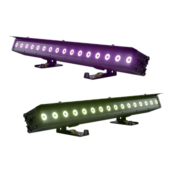
- Page 1 USER´S MANUAL BEDIENUNGSANLEITUNG MANUEL D`UTILISATION MANUAL DE USUARIO INSTRUKCJA OBSŁUGI MANUALE D‘ USO RGB W RGB WA PIXBAR ® IP65 LED BAR CLPB400IPG2 ( RGBW ) / CLPB600IPG2 ( RGBWAUV )
-
Page 2: Table Of Contents
CONTENTS / INHALTSVERZEICHNIS / CONTENU / CONTENIDO / TREŚĆ / CONTENUTO ENGLISH INFORMATION ON THIS USER MANUAL INTENDED USE DEFINITIONS AND SYMBOLS SAFETY INSTRUCTIONS NOTES ON PORTABLE OUTDOOR DEVICES PACKAGING CONTENT INTRODUCTION CONNECTIONS, OPERATING AND DISPLAY ELEMENTS OPERATION INSTALLATION FROST FILTER GLARE SHIELD CARE, MAINTENANCE AND REPAIR OPTIONAL ACCESSORIES... - Page 3 OPTIONALES ZUBEHÖR ABMESSUNGEN (mm) TECHNISCHE DATEN ERLÄUTERUNGEN ZUR IP-SCHUTZART MINDESTABSTAND ZUR BELEUCHTETEN FLÄCHE MINDESTABSTAND ZU NORMAL ENTFLAMMBAREN MATERIALIEN ENTSORGUNG HERSTELLERERKLÄRUNGEN FRANÇAIS INFORMATIONS SUR CE MANUEL D'UTILISATION UTILISATION PRÉVUE DÉFINITIONS ET EXPLICATION DES PICTOGRAMMES CONSIGNES DE SÉCURITÉ NOTES SUR LES APPAREILS PORTABLES POUR EXTÉRIEUR CONTENU DU CARTON INTRODUCTION CONNECTEURS, UTILISATION ET INDICATEURS...
- Page 4 CONTENTS / INHALTSVERZEICHNIS / CONTENU / CONTENIDO / TREŚĆ / CONTENUTO ESPAÑOL INFORMACIÓN SOBRE ESTE MANUAL DE USUARIO USO ADECUADO DEFINICIONES Y EXPLICACIONES DE LOS SÍMBOLOS INSTRUCCIONES DE SEGURIDAD INDICACIONES PARA EQUIPOS PORTÁTILES DE EXTERIOR ELEMENTOS SUMINISTRADOS INTRODUCCIÓN CONEXIONES, CONTROLES E INDICADORES OPERACIÓN MONTAJE FILTRO FROST...
- Page 5 AKCESORIA OPCJONALNE WYMIARY (mm) DANE TECHNICZNE WYJAŚNIENIE KLASY OCHRONY IP MINIMALNA ODLEGŁOŚĆ OD OŚWIETLANEJ POWIERZCHNI MINIMALNA ODLEGŁOŚĆ OD NORMALNIE ŁATWOPALNYCH MATERIAŁÓW UTYLIZACJA DEKLARACJE PRODUCENTA ITALIANO INFORMAZIONI SU QUESTO MANUALE D’ISTRUZIONI USO CONFORME SPIEGAZIONE DI TERMINI E SIMBOLI INDICAZIONI SULLA SICUREZZA AVVERTENZE PER DISPOSITIVI PORTATILI PER ESTERNI DOTAZIONE INTRODUZIONE...
-
Page 6: Information On This User Manual
This device has been developed and manufactured to the highest quality standards to ensure many years of problem-free operation. Please read this user manual carefully to be able to use your new Cameo product quickly and optimally. Further information about Cameo Light is availab- le on our website CAMEOLIGHT.COM. -
Page 7: Safety Instructions
This symbol identifies hazards that can cause electric shock. This symbol identifies hazardous areas or hazardous situations. This symbol indicates hazards caused by hot surfaces. This symbol indicates hazards caused by intense light sources. This symbol indicates a device in which there are no user-replaceable parts. This symbol indicates additional information on the operation of the product. - Page 8 ATTENTION: 1. Do not operate the unit if it has been exposed to large temperature fluctuations (for example, after transport). Moisture and condensation can damage the device. Switch on the device only when it has reached room temperature. 2. Make sure that the voltage and frequency of the mains supply correspond to the values indicated on the unit.
- Page 9 CAUTION: 1. In the case of moving components such as mounting brackets or other moving components, there is a possibility of jamming. 2. In the case of units with motor-driven components, there is a risk of injury from the movement of the unit. Sudden movement of the device can cause shock reactions. 3.
- Page 10 SIGNAL TRANSMISSION AND CONTROL BY RADIO (e.g. W-DMX or audio radio systems, Bluetooth): The quality and performance of wireless signal transmissions generally depends on the ambient conditions. The following factors can impact range and signal stability, for example: Shielding (e.g. masonry, metal structures, water) High volumes of radio traffic (e.g.
-
Page 11: Notes On Portable Outdoor Devices
NOTES ON PORTABLE OUTDOOR DEVICES 1. Temporary operation! Event equipment is generally only designed for temporary operation. 2. Continuous operation or permanent structural installation – particularly outdoors – can impair the function, surfaces and seals and accelerate material fatigue. 3. Damage to the surface coating can impair the device's corrosion protection. Damaged surface coating (e.g. - Page 12 The spotlights feature the RDM standard (remote device management). This remote device management enables the status query and configuration of RDM end devices via an RDM-capable controller, such as the optionally available Cameo UNICON (item number CLIREMOTE). The Cameo UNICON also allows access to the entire spotlight menu.
-
Page 13: Connections, Operating And Display Elements
IP65 mains output socket with rubber sealing cap (TRUE1 compatible). Facilitates power supply to other CAMEO spotlights. Ensure that the total current consumption of all connected devices does not exceed the value specified on the device in amperes (A) (when not in use, always close with the rubber sealing cap). -
Page 14: Operation
• As soon as the spotlight is correctly connected to the power supply, the following are displayed in succession: “Update wait ...” (for service purposes only), “Welcome to Cameo”, the model name and the software version. After this process, the spotlight is ready for operation and the previously activated operating mode is launched. - Page 15 • Note on the main display in the operating modes with external control: As soon as the control signal is interrupted, the characters in the display start flashing; if the control signal is present again, the flashing stops. • Briefly pressing UP when in the main display rotates the display by 180°. SETTING DMX START ADDRESS (DMX address) Starting from the main display, press MENU to enter the main menu.
- Page 16 DMX modes with DMX delay channel The DMX Delay function is a simple way to create a running light effect with a large number of spotlights that are all the same model and that are all running the same software version. This is otherwise only achievable with a suitable DMX controller and time-consuming programming.
- Page 17 This will take you to the submenu for configuring the submenu items (see table). Control signal is forwarded via DMX OUT Activate DMX control signal forwarding via W-DMX Deactivate sending of the DMX control signal via W-DMX Pairing with ready-to-pair W-DMX devices Disconnect all W-DMX connections Set DMX delay for slave units: Off, 0.1s - 2.0s Do not forward control signal...
- Page 18 COLOUR PRESET STAND-ALONE MODE 49 different colour presets plus eight individually adjustable user presets (see Edit User Color) are available. The brightness can be set at a higher level. Starting from the main display, press MENU to enter the main menu. Use UP and DOWN to select the menu item Stand Alone, confirm the selection, then select Color Preset and confirm again with ENTER.
- Page 19 STAND-ALONE OPERATION MODE PLAY LOOP (8-step colour sequences 1 - 8) The 8 available loops are pre-programmed at the factory, but can be customised in the Edit Loop menu item. The brightness can be set at a higher level. Starting from the main display, press MENU to enter the main menu.
- Page 20 EDITING USER-PRESETS (Edit User Color) The eight user presets available in the stand-alone mode Colour Preset can be edited individually. Starting from the main display, press MENU to enter the main menu. Using UP and DOWN you now select the menu item Stand Alone, confirm with ENTER, then select Edit User Color and confirm once again.
- Page 21 EZ REMOTE CONTROL VIA CAMEO UNICON (optionally available) Starting from the main display, press MENU to enter the main menu. Using UP and DOWN you now select the EZ Remote menu item and confirm by pressing ENTER. Now set the desired fixture ID (Fixture ID 1 - 8) and confirm the entry.
- Page 22 SLAVE MODE Standard slave operation: Starting from the main display, press MENU to enter the main menu. Using the UP and DOWN buttons, you now select the menu itemSlave confirm with ENTER, select the Slave Group 0 and confirm again with ENTER. Connect the slave and master units (same mo- del, same software version) using a DMX cable or W-DMX™...
- Page 23 SYSTEM SETTINGS (Settings) Starting from the main display, press MENU to enter the main menu. Using the UP und DOWN buttons you now select the menu item Settings and confirm with ENTER. This will take you to the submenu for setting the submenu items (see table, select with UP and DOWN, confirm with ENTER, change value or status with UP and DOWN, confirm with ENTER).
- Page 24 Dimmer curve: The light intensity increas- es linearly with the DMX value Dimmer curve: The light intensity can be adjusted finely in the lower DMX value range and coarsely in the upper DMX value range Dimming behaviour Dimmer curve: The light intensity can be and PWM adjusted coarsely in the lower DMX value frequency...
- Page 25 Last command is retained Operating Last activated stand-alone mode is started mode on 10s fade to blackout control signal Instant blackout interrup- User Colour 1 is activated tion Full On Function disabled Mirror pixel Pixels are mirrored Store all Store with ENTER system Store with ENTER settings...
- Page 26 SYSTEM INFORMATION (System Info) Starting from the main display, press MENU to enter the main menu. Select System Info using UP and DOWN and confirm with ENTER. Information on the submenu items in the system info menu and the corresponding options can be found in the table below (select with UP and DOWN, confirm with ENTER, change value or status with UP and DOWN, confirm with ENTER).
-
Page 27: Installation
INSTALLATION DANGEROverhead mounting requires extensive experience, including the calculation of the load limit values of the installation material and regular safety inspection of all installation materials and spotlights. If you do not have these qualifications, do not attempt to perform an installation yourself. Refer instead to a qualified professional. There is a risk that devices that are incorrectly mounted and secured may come loose and fall down. - Page 28 USE SPIN16 TV SPIGOT FOR MOUNTING The mounting feet of the PIXBAR® G2 have 16 mm TV spigots that can be extended and retracted without tools. To unfold a TV spigot, pull the spring-loaded locking bolt out of the locking hole in the direction of the arrow (1), fold the TV spigot forwards and let the locking bolt engage in the locking hole offset by 90°...
- Page 29 VERTICAL HANGING MOUNTING ON A TRUSS For vertical hanging mounting, up to three PIXBAR® G2 may be connected to each other. The following optionally available products must be used for this: A suitable truss clamp with sufficient load-bearing capacity for the total load (e.g.
- Page 30 VERTICAL FLOOR MOUNTING For vertical floor mounting, a maximum of two PIXBAR® G2 may be connected to each other. The following optionally available products must be used for this: One connector (item number CL- PBG2STACKKIT). One stop set (item number CLPBG2VER- TIMOUNT).
- Page 31 VERTICALLY SUSPENDED TRUSS VERTICAL FLOOR MOUNTING...
-
Page 32: Frost Filter
FROST FILTER A standard frost filter is included with the PIXBAR® G2. To insert the frost filter into the holder provided for it of the bar, open the sliding latch at one end of the bar ( , slide down the handle). -
Page 33: Care, Maintenance And Repair
CARE, MAINTENANCE AND REPAIR In order to ensure the long-term, proper functioning of the device, it must be regularly cleaned and, if necessary, maintained. The maintenance requirement depends on the intensity of use and the environment in which it is used. We generally recommend a visual inspection before each operation. -
Page 34: Optional Accessories
CLPBG2VERTIMOUNT Stop set for mounting a PIXBAR® G2 on the Omega mounting bracket CLOMEGABRACKET1 and for mounting on the connection set CLPBG2M20ADA CLOMEGABRACKET1 Omega mounting bracket CLPBG2M20ADA Connection set for mounting a PixBar G2 on a stand with M20 thread... -
Page 35: Dimensions (Mm)
DIMENSIONS (mm) 1000 1000 1018 98,5... -
Page 36: Technical Data
TECHNICAL DATA Item number CLPB400IPG2 CLPB600IPG2 Product category LED light LED light Type LED bars LED bars Light source 16 x 4in1 RGBW 16 x 6in1 RGBWAUv 5300lm @ Full On; R: 1580lm; G: 6500lm @ 6300K; R: 2500lm; G: Luminous flux 2755lm;... - Page 37 Pixel: R1, G1, B1, W1,... R16, G16, (EZ-Chase); Pixel: R1, G1, B1, W1, A1, B16, W16 Uv1,... R16, G16, B16, W16, A16, Uv16 DMX functions: Cameo standard RDM functions Cameo standard RDM functions Auto; Static; CCT; HSI; Colour Preset; Auto; Static; CCT; HSI; Colour Preset; Standalone Play Loop;...
-
Page 38: Explanations On Ip Rating
Max. current 0.77 A @ 230 V / 1.62 A @ 110 V 0.77 A @ 230 V / 1.62 A @ 110 V Inrush current Max power 180 V, 230 V, 110 V 180 V, 230 V, 110 V consumption STANDBY LED Power connec-... -
Page 39: Minimum Distance To Illuminated Surface
IPX5 Protection against water jets (nozzle) from any angle IPX6 Protection against strong water jets IPX7 Protection against temporary immersion 4. In addition, some device-specific measures such as covers and sealing caps are necessary in order to achieve the specified rating (e.g. protective caps on unused connections). The IP rating of the product can be found in the technical data and is printed on the device. -
Page 40: Manufacturer's Declarations
MANUFACTURER’S DECLARATIONS Manufacturer's warranty & limitation of liability Adam Hall GmbH | Adam-Hall-Str.1 | 61267 Neu-Anspach | Germany E-mail: Info@adamhall.com / +49 (0)6081 / 9419-0. Our current warranty conditions and limitation of liability can be found at: https://cdn-shop.adamhall.com/media/pdf/Manufacturers-Declarations-CAMEO_DE_EN_ES_FR.pdf For service requests, please contact your distribution partner. CE conformity Adam Hall GmbH hereby confirm that this product meets the following guidelines (where applica- ble):... -
Page 41: Deutsch
Dieses Gerät wurde unter hohen Qualitätsanforderungen entwickelt und gefertigt, um viele Jahre einen reibungslosen Betrieb zu gewährleisten. Bitte lesen Sie diese Bedienungsanleitung sorgfäl- tig, damit Sie Ihr neues Produkt von Cameo Light schnell und optimal einsetzen können. Weitere Informationen über Cameo Light erhalten Sie auf unserer Website CAMEOLIGHT.COM. -
Page 42: Sicherheitshinweise
Dieses Symbol kennzeichnet Gefahren, die einen elektrischen Schlag verursachen können. Dieses Symbol kennzeichnet Gefahrenstellen oder gefährliche Situationen. Dieses Symbol kennzeichnet Gefahren durch heiße Oberflächen. Dieses Symbol kennzeichnet Gefahren durch intensive Lichtquellen. Dieses Symbol kennzeichnet ein Gerät, in dem sich keine vom Benutzer austauschba- ren Teile befinden. - Page 43 ACHTUNG: 1. Nehmen Sie das Gerät nicht in Betrieb, wenn es starken Temperaturschwankungen ausgesetzt war (beispielsweise nach dem Transport). Feuchtigkeit und Kondensat könnten das Gerät beschädigen. Schalten Sie das Gerät erst ein, wenn es Umge- bungstemperatur erreicht hat. 2. Stellen Sie sicher, dass die Spannung und die Frequenz des Stromnetzes mit den auf dem Gerät angegebenen Werten übereinstimmen.
- Page 44 VORSICHT: 1. Bei beweglichen Bauteilen wie Montagebügeln, oder sonstigen beweglichen Bau- teilen besteht die Möglichkeit sich zu klemmen. 2. Bei Geräten mit motorisch angetriebenen Bauteilen besteht Verletzungsgefahr durch die Bewegung des Gerätes. Plötzliche Gerätebewegungen können zu Schreckreaktionen führen. 3. Die Gehäuseoberfläche des Geräts kann sich im regulären Betrieb stark erwärmen. Stellen Sie sicher, dass ein versehentliches Berühren des Gehäuses ausgeschlos- sen ist.
- Page 45 SIGNALÜBERTRAGUNG UND STEUERUNG PER FUNK (z.B. W-DMX oder Audio-Funksysteme, Bluetooth): Die Qualität und Leistungsfähigkeit kabelloser Signalübertragungen ist generell abhängig von den Umgebungsbedingungen. Einfluss auf die Reichweite und Signalstabilität haben z.B.: Abschirmung (z.B. Mauerwerk, Metallbauten, Wasser) Hohes Funkaufkommen (z.B. starke W-LAN Netze) Interferenzen Elektromagnetische Strahlung (z.B.
-
Page 46: Hinweise Für Ortsveränderliche Outdoor-Geräte
HINWEISE FÜR ORTSVERÄNDERLICHE OUTDOOR-GERÄTE 1. Temporärer Betrieb! Veranstaltungsequipment ist grundsätzlich nur für den vorü- bergehenden Betrieb konzipiert. 2. Dauerbetrieb oder dauerhafte bauliche Anbringung, besonders im Außenbereich, kann zur Beeinträchtigung der Funktion, sowie der Oberflächen und Dichtungen und zu beschleunigter Materialermüdung führen. 3. - Page 47 Die Scheinwerfer verfügen über den RDM-Standard (Remote Device Management). Diese Gerätefernverwaltung ermöglicht die Statusabfrage und Konfiguration von RDM-Endgeräten über einen RDM-fähigen Controller, wie den optional erhältlichen Cameo UNICON (Artikelnummer CLIRE- MOTE). Der Cameo UNICON ermöglicht darüber hinaus den Zugriff auf das gesamte Scheinwerfer- menü.
-
Page 48: Anschlüsse, Bedien- Und Anzeigeelemente
POWER OUT IP65 Netzausgangsbuchse mit Gummidichtkappe (TRUE1 kompatibel). Dient der Netzversorgung weiterer CAMEO Scheinwerfer. Achten Sie darauf, dass die gesamte Stromaufnahme aller ange- schlossenen Geräte den auf dem Gerät in Ampere (A) angegebenen Wert nicht überschreitet (bei Nichtgebrauch stets mit der Gummidichtkappe verschließen). -
Page 49: Bedienung
ANMERKUNGEN • Sobald der Scheinwerfer korrekt am Stromnetz angeschlossen ist, wird während des Start- vorgangs nacheinander „Update wait..“ (nur für Service-Zwecke), „Welcome to Cameo“, die Modellbezeichnung und die Softwareversion im Display angezeigt. Nach diesem Vorgang ist der Scheinwerfer betriebsbereit und die Betriebsart, die zuvor aktiviert war, wird gestartet. - Page 50 DMX-STARTADRESSE EINSTELLEN (DMX Address) Ausgehend von der Hauptanzeige gelangen Sie durch Drücken auf MENU in das Hauptmenü. Mit Hilfe von UP und DOWN wählen Sie nun den Menüpunkt DMX Address aus und bestätigen mit ENTER. Stellen Sie die gewünschte DMX-Startadresse mit Hilfe von UP und DOWN ein und bestätigen die Eingabe mit ENTER (höchster Wert abhängig von der aktuell eingestellten DMX-Be- triebsart).
- Page 51 Einstellen des DMX-Delays: Wählen Sie eine der DMX-Betriebsarten mit DMX-Delay-Kanal aus und bestätigen die Auswahl (im Beispiel D4 CH Preset). Ordnen Sie die Scheinwerfer nach Wunsch einer von bis zu 24 Gruppen zu (plus Gruppe 0), wobei auch mehrere Scheinwerfer einer Grup- pe zugeordnet werden können.
- Page 52 Ausgehend von der Hauptanzeige gelangen Sie durch Drücken auf MENU in das Hauptmenü (Menu). Wählen Sie nun den Menüpunkt Stand Alone aus, bestätigen, wählen Master/Alone aus und bestätigen abermals. Daraufhin gelangen Sie in das Untermenü zum Einstellen der Untermenüpunkte (siehe Tabelle). Steuersignal wird via DMX OUT weitergeleitet Weiterleiten des DMX-Steuersignals per W-DMX aktivieren...
- Page 53 STAND-ALONE-BETRIEBSART COLOR PRESET 49 verschiedene Farb-Presets plus acht individuell einstellbare User-Presets (siehe Edit User Color) stehen zur Verfügung. Die Helligkeit kann übergeordnet eingestellt werden. Ausgehend von der Hauptanzeige gelangen Sie durch Drücken auf MENU in das Hauptmenü. Mit Hilfe von UP und DOWN wählen Sie nun den Menüpunkt Stand Alone aus, bestätigen die Auswahl, wählen dann Color Preset aus und bestätigen abermals mit ENTER.
- Page 54 STAND-ALONE-BETRIEBSART HSI (Hue - Saturation - Intensity) In der Stand-Alone-Betriebsart HSI können der Farbton (Hue), die Farbsättigung (Saturation) und die Helligkeit (Dimmer) separat nach Wunsch eingestellt werden. Ausgehend von der Hauptan- zeige gelangen Sie durch Drücken auf MENU in das Hauptmenü. Mit Hilfe von UP und DOWN wählen Sie nun den Menüpunkt Stand Alone aus, bestätigen die Auswahl, wählen dann HSI aus und bestätigen abermals mit ENTER.
- Page 55 Sie können nun den jeweiligen Wert nach Wunsch einstellen. Bestätigen Sie alle Eingaben. Zum Deaktivieren der Timer-Funktion wählen Sie unter Punkt Timer die Einstellung Off aus und bestä- tigen die Eingabe. Hinweis: Die Timer-Funktion ist für den Einsatz im Master/Slave-Betrieb via Kabel und W-DMX ™...
- Page 56 LOOP EDITIEREN (Edit Loop) Die Helligkeit, die Schrittdauer und die Überblendzeit sind bei allen acht Loops separat einstellbar. Ausgehend von der Hauptanzeige gelangen Sie durch Drücken auf MENU in das Hauptmenü. Mit Hilfe von UP und DOWN wählen Sie nun den Menüpunkt Stand Alone aus, bestätigen mit ENTER, wählen dann Edit Loop aus und bestätigen abermals.
- Page 57 EZ REMOTE STEUERUNG PER CAMEO UNICON (optional erhältlich) Ausgehend von der Hauptanzeige gelangen Sie durch Drücken auf MENU in das Hauptmenü. Mit Hilfe von UP und DOWN wählen Sie nun den Menüpunkt EZ Remote aus und bestätigen durch Drücken auf ENTER. Stellen Sie nun die gewünschte Geräte-ID (Fixture ID 1 - 8) ein und bestä- tigen die Eingabe.
- Page 58 Erweiterter Slave-Betrieb: Wenn Sie beim Master / Slave-Betrieb die Steuerung der Slave-Ein- heiten durch eine der Stand-Alone-Betriebsarten Auto Program oder Play Loop durchführen möchten, kann das Steuersignal in bis zu 24 Stufen zeitlich verzögert wiedergegeben werden, die Verzögerung wird im Stand Alone Menü Master/Alone in der Master-Einheit übergeordnet eingestellt, der Verzögerungsfaktor im Slave-Menü...
- Page 59 Daraufhin gelangen Sie in das Untermenü zum Einstellen der Untermenüpunkte (siehe Tabelle, Auswahl mit UP und DOWN, bestätigen mit ENTER, Wert bzw. Status ändern mit UP und DOWN, bestätigen mit ENTER). W-DMX aktiviert W-DMX deaktiviert W-DMX-Betriebsart: Empfänger G3 (Sendestandard G3) G4s (Sendestandard G4s ) Entkoppeln aller Geräte und Koppelbereit- schaft versetzen...
- Page 60 Dimmerkurve: Die Lichtintensität steigt linear mit dem DMX-Wert an Dimmerkurve: Die Lichtintensität lässt sich im unteren DMX-Wertbereich fein und im oberen DMX-Wertbereich grob einstellen Dimmerkurve: Die Lichtintensität lässt sich im unteren DMX-Wertbereich grob und im oberen DMX-Wertbereich fein einstellen Dimmerkurve: Die Lichtintensität lässt sich im unteren und oberen DMX-Wertbereich fein und im mittleren DMX-Wertbereich grob einstellen...
- Page 61 R, G, B, und W (CLPB400IPG2) bzw. R, G, B, W, A und Uv (CLPB600IPG2) mit Maxi- malwert 255 Individuelle Farb-Kalibrierung. Betriebsa- Color rtübergreifende Helligkeitseinstellung mit Calibra- Werten von 0 - 255 tion Werksseitige Kalibrierung (betriebsar- tübergreifend) Zusammenführung von Factory- und RAW-Kalibrierung Letzter Befehl wird gehalten Zuletzt aktivierte Stand-Alone-Betriebsart...
- Page 62 SERVICE-MENÜ (Service) Ausgehend von der Hauptanzeige gelangen Sie durch Drücken auf MENU in das Hauptmenü (Main Menu). Wählen Sie mit Hilfe von UP und DOWN Service aus und bestätigen mit ENTER. Informationen zu den Untermenüpunkten im Service-Menü und den entsprechenden Optionen finden Sie in untenstehender Tabelle (Auswahl mit UP und DOWN, bestätigen mit ENTER, Wert bzw.
-
Page 63: Montage
Vx.x.x Anzeige der Firmware-Version der entsprechenden Komponente Vx.x.x Anzeige der Temperatur der entspre- xxx °C/°F chenden Komponente °C Einstellen der Temperatureinheit °F xxxx h : xx m Gesamtbetriebszeit xxxx h : xx m Nutzzeit xxxx h : xx m Betriebszeit des Leuchtmittels Betriebszeit nach dem Zurücksetzen xxxx h : xx m der Service-Betriebszeit... - Page 64 MONTAGE EINER PIXBAR AN EINER TRAVERSE ® Die Montage an einer Traverse erfolgt mit Hilfe optional erhältlicher Traversenklemmen, die entweder direkt an den Montagefüßen befestigt werden (1), oder an optional erhältlichen Ome- ga-Montagebügeln (Artikelnummer CLOMEGABRACKET1). Die Montagefüße können am Gehäuse der PIXBAR G2 verschoben werden, lösen Sie dafür die mittlere der fünf Innensechskantschrau- ®...
- Page 65 SPIN16 TV-ZAPFEN FÜR DIE MONTAGE VERWENDEN Die Montagefüße der PIXBAR G2 verfügen über werkzeuglos aus- und einklappbare 16 mm ® TV-Zapfen. Zum Ausklappen eines TV-Zapfens ziehen Sie den gefederten Verriegelungsbolzen in Pfeilrichtung aus dem Verriegelungsloch (1), klappen den TV-Zapfen nach vorne und lassen den Verriegelungsbolzen in das um 90°...
- Page 66 VERTIKAL HÄNGENDE MONTAGE AN EINER TRAVERSE Für die vertikal hängende Montage dürfen bis zu drei PIXBAR G2 miteinander ver- ® bunden werden. Hierfür müssen folgende optional erhältliche Produkte verwendet werden: Eine geeignete Traversenklemme mit ausreichender Tragkraft für die Gesamt- last (z.B. Halfcoupler). Ein Omega Bracket (Artikelnummer CLOMEGABRACKET1).
- Page 67 SENKRECHTE BODENMONTAGE Für die senkrechte Bodenmontage dürfen maximal zwei PIXBAR G2 miteinander ® verbunden werden. Hierfür müssen folgende optional erhältliche Produkte verwendet werden: Ein Verbindungselement (Artikelnummer CLPBG2STACKKIT). Ein Anschlagset (Artikelnummer CLPBG2VERTIMOUNT). Ein M20 Verbindungsset (Artikelnummer CLPBG2M20ADA). Ein schwerer Standfuß aus Stahl mit M20 Gewinde und ausreichender Stand- festigkeit für die Gesamtlast.
- Page 68 VERTIKAL HÄNGENDE TRAVERSE SENKRECHTE BODENMONTAGE...
-
Page 69: Frostfilter
FROSTFILTER Ein Standard Frostfilter ist im Lieferumfang der PIXBAR G2 enthalten. Um den Frostfilter in die ® dafür vorgesehene Halterung (1) der Bar einzusetzen, öffnen Sie den Schieberiegel an einem Ende der Bar ((2), am Griff nach unten schieben). Nachdem Sie den Frostfilter in die Halterung einge- setzt haben, schließen Sie den Riegel wieder, um das Herausfallen des Filters zu verhindern. -
Page 70: Pflege, Wartung Und Reparatur
PFLEGE, WARTUNG UND REPARATUR Um die einwandfreie Funktion des Geräts auf Dauer zu gewährleisten, muss es regelmäßig ge- pflegt und bei Bedarf gewartet werden. Der Pflege- bzw. Wartungsbedarf steht in Abhängigkeit der Nutzungsintensität und -umgebung. Wir empfehlen generell eine Sichtprüfung vor jeder Inbetriebnahme. Weiterhin empfehlen wir alle 500 Betriebsstunden, oder bei geringerer Nutzungsintensität spätestens nach Ablauf eines Jahres alle unten genannten und zutreffenden Pflegemaßnahmen durchzuführen. -
Page 71: Optionales Zubehör
HINWEIS! Unsachgemäß ausgeführte Wartungsarbeiten können den Gewährleis- tungsanspruch beeinträchtigen. HINWEIS! Bei vom Hersteller vorgesehenen Um- oder Nachrüstsets beachten Sie unbedingt die beiliegende Einbauanleitung. OPTIONALES ZUBEHÖR CLPBG2FILTER55 55° Frostfilter CLPBG2FILTER70 70° Frostfilter CLPBG2FILTER2555 25° x 55° Frostfilter CLPBG2STACKKIT Verbindungselement für die sichere mechanische Verbindung von zwei PIXBAR ®... -
Page 72: Abmessungen (Mm)
ABMESSUNGEN (mm) 1000 1000 1018 98,5... -
Page 73: Technische Daten
TECHNISCHE DATEN Artikelnummer CLPB400IPG2 CLPB600IPG2 Produktkategorie Statische LED-Lampe Statische LED-Lampe LED-Leiste LED-Leiste Scheinwerfer 16 x 4in1 RGBW 16 x 6in1 RGBWAUv Lichtstrom 6500 lm @ 6300 K; R: 2500 lm; G: 5300 lm bei voller Leistung; R: 1580 3600 lm; B: 570 lm; W: 5000 lm lm;... - Page 74 R16, G16, B16, W16 Geräteeinstellungen; Gruppierung; DMX-Verzögerung (EZ-Chase); Pixel: R1, G1, B1, W1, A1, Uv1,... R16, G16, B16, W16, A16, Uv16 RDM-Funktionen Cameo Standard-RDM-Funktionen Cameo Standard-RDM-Funktionen Stand-Alone Auto; Statisch; CCT; HSI; Farbvorein- Auto; Statisch; CCT; HSI; Farbvorein- stellung; Wiedergabeschleife; Slave;...
-
Page 75: Erläuterungen Zur Ip-Schutzart
Kühlungssystem Passive Konvektion, lüfterlos Passive Konvektion, lüfterlos Rauschpegel Rauschfrei Rauschfrei Betriebsspan- 100 - 240 V AC, 50 - 60 Hz 100 - 240 V AC, 50 - 60 Hz nung Max. Stromauf- 0,77 A @ 230 V; 1,62 A @ 110 V 0,77 A @ 230 V; 1,62 A @ 110 V nahme Einschaltstrom 42 A... -
Page 76: Mindestabstand Zur Beleuchteten Fläche
3. Die zweite Kennziffer bezeichnet den Schutz gegen Wasser: IPX0 Kein Schutz IPX1 Schutz gegen Tropfwasser IPX2 Schutz gegen fallendes Tropfwasser, wenn das Gerät bis zu 15° geneigt ist IPX3 Schutz gegen fallendes Sprühwasser bis 60° gegen die Senkrechte IPX4 Schutz gegen allseitiges Spritzwasser IPX5 Schutz gegen Strahlwasser (Düse) aus beliebigem Winkel... -
Page 77: Herstellererklärungen
GERÄT: 1. Dieses Gerät unterliegt der europäischen Richtlinie für Elektro- und Elektronik-Alt- geräte in der jeweils geltenden aktuellen Fassung. WEEE-Richtlinie Waste Elec- trical and Electronical Equipment. Altgeräte gehören nicht in den Hausmüll. Das Altgerät muss über einen zugelassenen Entsorgungsbetrieb oder eine kommunale Entsorgungseinrichtung entsorgt werden. -
Page 78: Français
Veuillez lire attentivement ce manuel d'utilisation afin de pouvoir utiliser votre nouveau produit Cameo rapidement et de manière et optimale. De plus amples informations sur Cameo Light sont disponibles sur notre site web CAMEOLIGHT.COM. -
Page 79: Consignes De Sécurité
Ce pictogramme identifie les dangers qui peuvent causer un choc électrique. Ce pictogramme identifie les zones ou les situations dangereuses. Ce pictogramme indique les dangers causés par les surfaces portées à haute tempé- rature. Ce symbole indique les dangers causés par des sources lumineuses intenses. Ce symbole indique que l'appareil ne contient aucune pièce remplaçable par l'utilisa- teur. - Page 80 AVIS : 1. Ne faites pas fonctionner l'appareil s'il a été exposé à de fortes variations de tem- pérature (par exemple, après le transport). L'humidité et la condensation internes peuvent endommager l'appareil. N'allumez l'appareil qu'une fois qu'il a atteint la température ambiante. 2.
- Page 81 ATTENTION : 1. Dans le cas de composants mobiles tels que des supports de montage ou d'autres pièces similaires, il existe un risque de blocage. 2. Dans le cas des appareils dotés de composants motorisés, il existe un risque de blessure dû au mouvement de l'appareil. Un mouvement brusque de l'appareil peut provoquer des réactions de choc.
- Page 82 ATTENTION ! INFORMATIONS IMPORTANTES AU SUJET DES PRODUITS D'ÉCLAIRAGE ! 1. Ne regardez jamais directement le faisceau lumineux, même pendant un court instant. 2. Ne regardez jamais le faisceau lumineux à l'aide de dispositifs optiques tels qu'une loupe. 3. Les effets stroboscopiques peuvent provoquer des crises d'épilepsie chez les personnes sensibles.
-
Page 83: Notes Sur Les Appareils Portables Pour Extérieur
TRANSMISSION VIA W-DMX AVERTISSEMENT : Latransmission DMX sans fil ne doit pas être utilisée pour des applications présentant des facteurs de sécurité susceptibles d'entraîner des blessures ou des dommages matériels en cas de défaillance. Cela s'applique en particulier aux scènes et structures mobiles, aux moteurs/ascen- seurs ou dispositifs de levage commandés par DMX pour contrôle de plates-formes élévatrices, de systèmes hydrauliques ou de dispositifs mobiles similaires. -
Page 84: Introduction
à distance). Ce protocole de gestion à distance des appareils permet d'interroger leur état et de les configurer via un contrôleur compatible RDM, tel que le Cameo UNICON, disponible en option (référence CLIREMOTE). Le Cameo UNICON permet également d'accéder à l'ensemble du... -
Page 85: Connecteurs, Utilisation Et Indicateurs
POWER OUT Renvoi secteur IP65 avec capuchon d'étanchéité en caoutchouc (compatible TRUE1). Facilite l'alimentation d'autres projecteurs CAMEO. Assurez-vous que l'intensité totale consommée par tous les projecteurs connectés en cascade ne dépasse pas la valeur spécifiée sur l'appareil en ampères (A) (lorsque le renvoi secteur n'est pas utilisé, protégez-le toujours avec le capuchon d'étanchéité... -
Page 86: Fonctionnement
: "Update wait (Attente de mise à jour) ..." (à des fins de service uniquement), "Welcome to Cameo", puis le nom du modèle et la version du logiciel. Le projecteur est ensuite prêt à fonctionner, dans le dernier mode activé avant extinction. - Page 87 • Remarque sur l'écran principal dans les modes de fonctionnement avec contrôle externe : Dès que le signal de contrôle est interrompu, les caractères de l'écran commencent à clignoter ; le clignotement s'arrête dès le retour du signal de contrôle. •...
- Page 88 Modes DMX avec canal de retard DMX : La fonction DMX Delay est un moyen simple de créer un effet de lumière mobile avec un grand nombre de projecteurs, tous du même modèle et avec la même version du logiciel. Pour obtenir le même résultat, il faut utiliser un contrôleur DMX approprié, avec une programmation fastidieuse.
- Page 89 À partir de l'écran principal, appuyez sur MENU pour accéder au menu principal. Sélectionnez ensuite l'élément de menu Stand Alone, confirmez, sélectionnez Master/Alone et confirmez à nouveau. Vous accédez ainsi au sous-menu permettant de configurer les éléments du sous-menu (voir tableau) : Le signal de commande est transmis via la sortie DMX Active la transmission du signal de contrôle DMX via...
- Page 90 CLPB400IPG2 CLPB600IPG2 MODE AUTONOME COLOUR PRESET Vous disposez de 49 préréglages de couleur différents et de huit préréglages utilisateur réglables individuellement (voir Edit User Color). La luminosité peut être réglée de manière très précise. À partir de l'écran principal, appuyez sur MENU pour accéder au menu principal. Utilisez les touches HAUT et BAS pour sélectionner l'élément de menu Stand Alone, confirmez la sélection, puis sé- lectionnez Color Preset et confirmez à...
- Page 91 MODE AUTONOME HSI (Hue - Saturation - Intensity) En mode autonome HSI, la teinte, la saturation et la luminosité peuvent être réglées séparément comme vous le souhaitez. À partir de l'écran principal, appuyez sur MENU pour accéder au menu principal. Utilisez les touches HAUT et BAS pour sélectionner l'élément de menu Stand Alone, confirmez la sélection, puis sélectionnez HSI et confirmez à...
- Page 92 FONCTION TIMER La fonction de minuterie permet de gérer les modes autonomes « Direct LED », « Colour Preset », « CCT » et « HSI » de manière contrôlée dans le temps, de sorte que la durée d’allumage (Fade In) puisse être réglée de 0 à 60 minutes, la durée d’illumination (Dwell Time) de 1 à 24 heures et la durée d’extinction (Fade Out) de 0 à...
- Page 93 ÉDITION DE BOUCLE (Edit Loop) La luminosité, la durée des pas et le temps de fondu peuvent être réglés séparément pour les huit boucles. À partir de l'écran principal, appuyez sur MENU pour accéder au menu principal. A l'aide des touches et , sélectionnez le point de menu Stand Alone, confirmez avec ENTER, puis sélectionnez Edit Loop et confirmez à...
- Page 94 CONTRÔLE EZ REMOTE VIA CAMEO UNICON (Disponible en option) À partir de l'écran principal, appuyez sur MENU pour accéder au menu principal. Utilisez les touches HAUT et BAS pour sélectionner l'élément de menu EZ Remote et confirmez en appuyant sur la touche ENTER. Réglez maintenant l'ID de l'appareil souhaité (Fixture ID 1 - 8) et confirmez la saisie.
- Page 95 Définit le groupe d'esclaves pour la temporisation du signal Active le module W-DMX Désactive le module W-DMX Débranche toutes les connexions et met le projecteur en mode d'attente d'appairage Affectez les projecteurs à l'un des 24 groupes (plus le groupe 0) selon vos préférences – vous pouvez affecter plusieurs projecteurs à...
- Page 96 W-DMX activé W-DMX désactivé Mode W-DMX : Récepteur Norme d'émission G3 Norme d'émission G4S Désapparie tous les projecteurs et les prépare à un nouvel appairage Appairer des appareils W-DMX. Le W-DMX doit être activé sur tous les appareils et l'appairage avec un émetteur doit être conservé...
- Page 97 Courbe de gradation : L'intensité lumineu- se varie grossièrement dans la plage de valeurs DMX inférieure et finement dans la plage de valeurs DMX supérieure L’intensité lumineuse varie finement pour les valeurs DMX basses et élevées, et plus grossièrement pour les valeurs DMX intermédiaires Sélection de la fréquence PWM (modula- tion de largeur d'impulsion) de la LED...
- Page 98 Maintien de la dernière commande reçue Le dernier mode autonome activé est lancé Fondu au noir de 10 s Extinction instantanée La couleur utilisateur 1 est activée Plein feu Fonction désactivée Pixel miroir Les pixels sont réfléchis Mémoriser avec ENTER Mémoriser avec ENTER Mémoriser avec ENTER MENU SERVICE (Service)
- Page 99 Annule l'opération Réinitialisation de la valeur de durée d'utilisation Pour technicien de service uniquement INFORMATIONS SYSTÈME (System Info) À partir de l'écran principal, appuyez sur MENU pour accéder au menu principal. Sélectionnez System Info à l'aide des touches HAUT et BAS et confirmez avec la touche ENTER. Vous trouverez dans le tableau ci-dessous des informations sur les éléments du sous-menu du menu info système et les options correspondantes (sélectionnez avec HAUT et BAS, confirmez avec ENTER, modifiez la valeur ou l'état avec HAUT et BAS, confirmez avec ENTER).
-
Page 100: Montage
MONTAGE DANGER : Le montage au plafond nécessite une grande expérience, notamment pour calculer les valeurs limites de charge du matériel d’installation et pour vérifier régulièrement la sécurité de tous les matériaux d’installation et des projecteurs. Si vous ne possédez pas ces qualifications, n'essayez pas d'effectuer l'installation vous-même. - Page 101 UTILISEZ L'EMBOUT TV SPIN16 POUR LE MONTAGE Les pieds de montage de la PIXBAR G2 sont dotés d'embouts TV de 16 mm qui peuvent être ® déployés et rétractés sans outils. Pour déplier un embout TV, tirez le boulon de verrouillage à ressort hors du trou de verrouillage, dans le sens de la flèche (1), pliez l'embout TV vers l'avant et laissez le boulon de verrouillage s'engager dans le trou de verrouillage décalé...
- Page 102 MONTAGE VERTICAL SUSPENDU SUR BARRE TRANSVERSALE Pour un montage vertical suspendu, jusqu'à trois PIXBAR G2 peuvent être fixées les ® unes aux autres. Les produits suivants, disponibles en option, doivent être utilisés à cet effet : Un collier de serrage approprié ayant une capacité...
- Page 103 MONTAGE VERTICAL AU SOL Pour un montage vertical au sol, un maxi- mum de deux PIXBAR G2 peuvent être ® reliées l'une à l'autre. Les produits suivants, disponibles en option, doivent être utilisés à cet effet : Une pièce de liaison (référence CLPBG2STACKKIT).
- Page 104 BARRE TRANSVERSALE SUSPENDUE MONTAGE VERTICAL AU SOL VERTICALEMENT...
-
Page 105: Filtre Frost
FILTRE FROST Un filtre frost standard est fourni avec la PIXBAR G2. Pour insérer le filtre frost dans le support ® prévu à cet effet (1) de la barre, ouvrez le loquet coulissant à l'une des extrémités de la barre ((2), faites glisser la poignée vers le bas). -
Page 106: Entretien, Maintenance Et Réparations
ENTRETIEN, MAINTENANCE ET RÉPARATIONS Afin de garantir le bon fonctionnement à long terme de l'appareil, celui-ci doit être régulièrement nettoyé et, si nécessaire, passer en maintenance. Le besoin de maintenance dépend de l'intensité de l'utilisation et de l'environnement dans lequel il est utilisé. Nous recommandons généralement une inspection visuelle avant chaque utilisation. -
Page 107: Accessoires En Option
MAINTENANCE ET RÉPARATION (uniquement par du personnel qualifié) DANGER ! L'appareil renferme des composants sous tension. Même après avoir débranché la fiche de la prise secteur, il peut subsister une tension résiduelle dans l'appareil, par exemple en raison de condensateurs chargés. À... -
Page 108: Dimensions (Mm)
DIMENSIONS (mm) 1000 1000 1018 98,5... -
Page 109: Caractéristiques Techniques
CARACTÉRISTIQUES TECHNIQUES Référence CLPB400IPG2 CLPB600IPG2 produit Catégorie de Éclairage LED statique Éclairage LED statique produit Type Barre LED Barre LED Source lumineuse 16 x LED 4in1 RGBW 16 x LED 6in1 RGBWAUv 5300 lm @ Plein feu ; R : 1580 lm ; G : 6500 lm @ 6300K ;... - Page 110 (EZ-Chase); Pixel: R1, G1, B1, W1, A1, Uv1,... R16, G16, B16, W16, A16, Uv16 Fonctions RDM Fonctions RDM standard Cameo Fonctions RDM standard Cameo Auto ; Statique ; CCT ; HSI ; Auto ; Statique ; CCT ; HSI ; Préréglage Autonome Préréglage des couleurs ;...
- Page 111 Indice IP IP65 pour une utilisation en extérieur IP65 pour une utilisation en extérieur Température am- biante nominale T -20°C - 45°C (appareil) T -20°C - 45°C (appareil) (en fonctionne- -10°C - 45°C (afficheur) -10°C - 45°C (afficheur) ment) Humidité Jusqu'à...
-
Page 112: Explication De La Classe De Protection Ip
EXPLICATION DE LA CLASSE DE PROTECTION IP 1. Un indice IP décrit uniquement la protection contre les objets solides et l’eau. Il ne décrit pas la résistance générale aux intempéries, comme la protection contre les rayons UV et les influences thermiques, etc. 2. -
Page 113: Distance Minimale Par Rapport Aux Matériaux Normalement
DISTANCE MINIMALE PAR RAPPORT AUX MATÉRIAUX NORMALEMENT INFLAMMABLES Ce symbole accompagné d'une indication de distance en mètres (m) indique la distance minimale de l'appareil par rapport aux matériaux normalement inflammables. Dans cet exemple, la distance est de 0,5 m. Pour connaître la 0,5 m valeur valable pour cet appareil, veuillez vous référer aux données techniques de ce manuel ! - Page 114 Directive basse tension (2014/35/UE) Directive CEM (2014/30/UE) RoHS (2011/65/EU) RED (2014/53/EU) Déclaration de conformité CE Les déclarations de conformité pour les produits soumis aux directives LVD, EMC, RoHS peuvent être demandées à info@adamhall.com Les déclarations de conformité des produits soumis à la directive RED peuvent être téléchargées sur www.adamhall.com/compliance/.
-
Page 115: Español
Este equipo está diseñado y fabricado con los estándares de calidad más exigentes, para garan- tizar un correcto funcionamiento durante muchos años. Lea atentamente este manual de usuario para poder aprovechar rápidamente toda la funcionalidad de su nuevo producto de Cameo Light. Más información sobre Cameo Light en la web CAMEOLIGHT.COM. -
Page 116: Instrucciones De Seguridad
Este símbolo indica peligro de descarga eléctrica. Este símbolo identifica las zonas o situaciones peligrosas. Este símbolo indica peligro por superficie a alta temperatura. Este símbolo indica peligro debido a fuente de luz intensa. Este símbolo indica que en el equipo no hay piezas que pueda sustituir el usuario. Este símbolo indica información complementaria sobre el uso del producto. - Page 117 ATENCIÓN: 1. Si el equipo ha estado expuesto a un cambio brusco de temperatura (por ejemplo, después del transporte), no lo encienda inmediatamente. La condensación o la humedad podrían dañar el equipo. No encienda el equipo hasta que haya alcanza- do la temperatura ambiente.
- Page 118 PRECAUCIÓN: 1. En el caso de los componentes móviles, como los soportes de montaje u otros elementos móviles, existe la posibilidad de que se atasquen. 2. En el caso de los equipos con componentes accionados por motor, existe riesgo de lesiones por el movimiento del equipo.
- Page 119 ¡PRECAUCIÓN!: ¡INFORMACIÓN IMPORTANTE SOBRE LOS PRODUCTOS DE ILUMINACIÓN! 1. No mire directamente el haz de luz, ni siquiera momentáneamente. 2. No mire directamente el haz de luz con instrumentos ópticos, como lentes de aumento. 3. ¡Los efectos estroboscópicos pueden a veces causar convulsiones en personas fotosensibles! 4.
-
Page 120: Indicaciones Para Equipos Portátiles De Exterior
TRANSMISIÓN DE SEÑALES POR W-DMX ADVERTENCIA: En general, la transmisión DMX inalámbrica no debe utilizarse para aplicaciones con factores relacionados con la seguridad que puedan provocar lesiones personales o daños materiales en caso de fallo. Esto se aplica en particular a las estructuras móviles de escenarios o trusses, motores/ elevadores controlados por DMX o equipos de elevación que accionan por DMX plata- formas elevadoras controladas, sistemas hidráulicos o componentes móviles similares. -
Page 121: Introducción
Esta característica de gestión remota permite consultar el estado y la configuración de equipos RDM mediante un controlador compatible con RDM, como el Cameo UNICON, disponible como accesorio opcional (ref. CLIREMOTE). El Cameo UNICON también permite acceder a todo el... -
Page 122: Conexiones, Controles E Indicadores
Salida eléctrica IP65 con tapa hermética de goma (compatible con TRUE1). Sirve para alimentar otros focos CAMEO. Asegúrese de que el consumo total de todos los equipos conectados no su- pere los amperios especificados del equipo (cuando no se utilice, dejar siempre la tapa cerrada). -
Page 123: Operación
«Update wait.» (solo para mantenimien- to), «Welcome to Cameo», el modelo del equipo y la versión del software. Al terminar el proce- so, el equipo ya está listo para funcionar y se activará el modo de funcionamiento seleccionado previamente. - Page 124 • Nota sobre la pantalla principal en los modos de funcionamiento con control externo: En cuanto se interrumpe la señal de control, los caracteres de la pantalla empiezan a parpadear; si la señal de control vuelve a estar presente, el parpadeo se detendrá. •...
- Page 125 Modos operativos DMX con canal de retardo DMX: Con la función retardo de DMX se puede crear un efecto de luces en movimiento de manera sencilla con cualquier número de focos del mismo modelo y con la misma versión de software, lo que normalmente solo se podría hacer con un controlador DMX adecuado y mucha programación.
- Page 126 Accederá al submenú en el que podrá configurar las opciones de la tabla siguiente. La señal de control se envía por DMX OUT Activada la transmisión de la señal de control DMX por W-DMX Desactivada la transmisión de la señal de control DMX por W-DMX Emparejar con equipos W-DMX listos para emparejar Desconectar todas las conexiones W-DMX...
- Page 127 MODO AUTÓNOMO. COLOR PRESET Dispone de 49 preajustes de color y 8 preajustes de usuario ajustables de forma independiente (consulte la sección Edit User Color). La intensidad puede ajustarse en el nivel superior. Desde la pantalla principal, pulse MENU para ir al menú principal. Pulse UP y DOWN para seleccionar la opción de menú...
- Page 128 MODO AUTÓNOMO. PLAY LOOP (Secuencias de color 1-8 de 8 pasos) Los 8 bucles disponibles vienen preprogramados de fábrica, pero pueden personalizarse desde la opción Edit Loop. La intensidad puede ajustarse en el nivel superior. Desde la pantalla principal, pulse MENU para ir al menú principal. Pulse los botones UP y DOWN para seleccionar la opción del menú...
- Page 129 Nota: La función de temporizador es adecuada para el funcionamiento maestro/esclavo por cable y W-DMX ™ EDITAR PREAJUSTES DE USUARIO (Edit User Color) Los ocho presets de usuario disponibles en el modo autónomo Color Preset se pueden editar de forma individual. Desde la pantalla principal, pulse MENU para ir al menú principal. Ahora, utilice los botones UP y DOWN para seleccionar la opción del menú...
- Page 130 CONTROL EZ REMOTE CON UNICON DE CAMEO (disponible opcionalmente) Desde la pantalla principal, pulse MENU para ir al menú principal. A continuación, utilice los botones UP y DOWN para seleccionar la opción EZ Remote del menú y pulse ENTER para confirmar.
- Page 131 Modo esclavo ampliado: Si desea controlar los equipos esclavos mediante uno de los modos autónomos Auto Program o Play Loop en modo maestro/esclavo, la señal de control puede re- producirse con un retardo de hasta 24 pasos; el retardo se ajusta en el menú Stand Alone Mas- ter/Alone del equipo maestro;...
- Page 132 CONFIGURACIÓN (Settings) Desde la pantalla principal, pulse MENU para ir al menú principal. Con los botones UP y DOWN seleccione la opción de menú Settings y confirme con ENTER. Seguidamente se abre el submenú que permite ajustar las opciones de submenú (ver tabla; seleccionar con los botones UP y DOWN y confirmar con ENTER, modificar los valores o el estado con los botones UP y DOWN y confirmar con ENTER).
- Page 133 Curva de atenuación: La intensidad de la luz aumenta linealmente con el valor DMX Curva de atenuación: La intensidad de la luz se puede ajustar para que varíe poco a niveles bajos de DMX y mucho a niveles altos de DMX Curva de atenuación: La intensidad del foco varía mucho a niveles bajos de DMX y varía poco a niveles altos de DMX.
- Page 134 Último modo operativo Se inicia el último modo autónomo activado Desvanecimiento de 10 segundos hasta oscurecimiento Oscurecimiento instantáneo Se activa User Color 1 Full On Función desactivada Píxel espejo Los píxeles se reflejan Guardar con ENTER Guardar con ENTER Guardar con ENTER MENÚ...
- Page 135 Restablecer los valores de fábrica Restablecer los valores del usuario A (Guardar valores de usuario: Settings > Store Default) Restablecer los valores del usuario B (Guardar valores de usuario: Settings > Store Default) Restablecer los valores del usuario C (Guardar valores de usuario: Settings > Store Default) Cancelar el proceso Restablecer el tiempo de funcionamiento de servicio Solo para mantenimiento...
-
Page 136: Montaje
MONTAJE PELIGRO: El montaje en altura requiere mucha experiencia, incluido el cálculo de los valores límite de la carga de trabajo, el material de instalación utilizado y las comprobaciones de seguridad periódicas de todos los materiales de instalación y focos. Si no está cualificado para ello, no intente realizar la instalación por su cuenta y recurra a una empresa profesional. - Page 137 UTILICE EL ADAPTADOR DE ESPIGA SPIN16 PARA EL MONTAJE Los pies de montaje de la barra PIXBAR G2 tienen adaptador de espigas de 16 mm que pueden ® abrir y cerrarse sin necesidad de ninguna herramienta. Para abrir un adaptador de espiga, tire del perno de bloqueo con resorte para sacarlo del orificio de bloqueo en la dirección indicada (1), doble el adaptador de espiga hacia delante y deje que el perno de bloqueo encaje en el orificio de bloqueo desplazado 90°...
- Page 138 MONTAJE SUSPENDIDO VERTICAL EN UN TRUSS Para el montaje suspendido vertical, pueden acoplarse entre sí hasta tres barras PIX- G2. Para ello debe utilizar los siguien- ® tes productos disponibles como accesorios opcionales: Una abrazadera adecuada con capaci- dad de carga suficiente para el peso total (por ejemplo, una abrazadera simple).
- Page 139 MONTAJE VERTICAL EN EL SUELO Para el montaje vertical en el suelo, pueden conectarse entre sí un máximo de dos barras PIXBAR G2. Para ello debe utilizar ® los siguientes productos disponibles como accesorios opcionales: Un conector (ref. CLPBG2STACKKIT). Un accesorio de montaje vertical (ref. CLPBG2VERTIMOUNT).
- Page 140 TRAVESAÑO SUSPENDIDO VERTICALMENTE MONTAJE VERTICAL EN EL SUELO...
-
Page 141: Filtro Frost
FILTRO FROST Con la barra PIXBAR G2 se suministra un filtro difusor frost estándar. Para introducir el filtro ® difusor frost en el soporte previsto para ello (1) de la barra, abra el pestillo deslizante situado en un extremo de la barra ((2), deslice hacia abajo el pestillo). Tras introducir el filtro difusor frost en el soporte, vuelva a cerrar el pestillo para evitar que el filtro se caiga. -
Page 142: Cuidado, Mantenimiento Y Reparación
CUIDADO, MANTENIMIENTO Y REPARACIÓN Para garantizar el buen funcionamiento del equipo a largo plazo, hay que limpiarlo con regularidad y, si es necesario, hacerle las revisiones necesarias. Los requisitos de mantenimiento dependen de la intensidad de uso y del entorno en el que se utilice. Por lo general, recomendamos una inspección visual antes de cada puesta en marcha. -
Page 143: Accesorios Opcionales
¡NOTA! Los trabajos de mantenimiento realizados indebidamente pueden invalidar la garantía. ¡NOTA! Si se utilizan sets de conversión o reequipamiento, o accesorios suministra- dos por el fabricante, asegúrese de respetar el manual de instrucciones adjunto. ACCESORIOS OPCIONALES CLPBG2FILTER55 Filtro difusor frost de 55° CLPBG2FILTER70 Filtro difusor frost de 70°... -
Page 144: Dimensiones (Mm)
DIMENSIONES (mm) 1000 1000 1018 98,5... -
Page 145: Características Técnicas
CARACTERÍSTICAS TÉCNICAS Referencia CLPB400IPG2 CLPB600IPG2 Categoría de Luz LED estática Luz LED estática producto Tipo Barra LED Barra LED Fuente de luz 16 × RGBW 4 en 1 16 × RGBWAUV 6 en 1 5.300 lm a máx. intensidad. 6.500 lm a 6.300 K. R: 2.500 lm. Flujo luminoso R: 1.580 lm. - Page 146 R16, G16, B16, W16 píxel: R1, G1, B1, W1, A1, UV1... R16, G16, B16, W16, A16, Uv16 Funciones RDM: Funciones RDM estándar de Cameo Funciones RDM estándar de Cameo Auto; estático; CCT; HSI; preajuste Auto; estático; CCT; HSI; preajuste de Modo autónomo de color;...
-
Page 147: Explicación Sobre La Clase De Protección Ip
Tensión operativa 100-240 VCA 50/60 Hz 100-240 VCA 50/60 Hz Corriente máx. 0,77 A a 230 V. 1,62 A a 110 V 0,77 A a 230 V. 1,62 A a 110 V Corriente de 42 A 39 A inicio Consumo máx. 180 W a 230/110 V 180 W a 230/110 V Consumo en 9 W 9 W espera Conectores de Seetronic IP65 entrada y salida Seetronic IP65 entrada y salida alimentación... -
Page 148: Distancia Mínima A La Superficie Iluminada
IPX0 Sin protección IPX1 Protección contra gotas de agua IPX2 Protección contra la caída de gotas de agua cuando el equipo está inclinado hasta 15° IPX3 Protección contra el agua rociada hasta 60° respecto a la vertical IPX4 Protección contra las salpicaduras de agua por todos los lados IPX5 Protección contra chorros de agua a presión desde cualquier ángulo IPX6... -
Page 149: Declaración Del Fabricante
Los aparatos viejos deben eliminarse a través de un servicio de eliminación de residuos autorizado o de una instalación municipal de eliminación de residuos. Respete la normativa vigente en su país. 2. Respete todas las leyes de eliminación aplicables en su país. 3. -
Page 150: Polski
Urządzenie to zostało opracowane i wyprodukowane zgodnie z najwyższymi standardami jakości, aby zapewnić wiele lat bezproblemowej pracy. Proszę uważnie przeczytać niniejszą instrukcję obsługi, aby móc szybko i optymalnie korzystać z nowego produktu Cameo. Więcej informacji na temat Cameo Light znajdą Państwo na naszej stronie internetowej CAMEOLIGHT.COM. -
Page 151: Instrukcje Bezpieczeństwa
Ten symbol wskazuje na zagrożenia, które mogą spowodować porażenie prądem. Ten symbol oznacza niebezpieczne obszary lub niebezpieczne sytuacje. Ten symbol oznacza zagrożenia spowodowane gorącymi powierzchniami. Ten symbol oznacza zagrożenia powodowane przez intensywne źródła światła. Ten symbol oznacza urządzenie, w którym nie ma części wymienianych przez użyt- kownika. - Page 152 UWAGA: 1. Nie używać urządzenia, jeżeli było narażone na duże wahania temperatury (np. po transporcie). Wilgoć i kondensacja mogą uszkodzić urządzenie. Urządzenie należy włączać dopiero wtedy, gdy osiągnie temperaturę pokojową. 2. Upewnić się, że napięcie i częstotliwość sieci zasilającej odpowiadają wartościom podanym na urządzeniu.
- Page 153 PRZESTROGA! 1. W przypadku ruchomych elementów, takich jak wsporniki montażowe lub inne ruchome elementy, istnieje możliwość zakleszczenia. 2. W przypadku urządzeń z elementami napędzanymi silnikiem istnieje ryzyko obra- żeń spowodowanych ruchem urządzenia. Nagły ruch urządzenia może wywołać reakcje szokowe. 3. Powierzchnia obudowy urządzenia może się bardzo nagrzewać podczas regularnej pracy.
- Page 154 4. Te urządzenia oświetleniowe wyposażone zostały w źródla światła zainstalowane na stałe. Nie mogą być one wymieniane przez użytkownika. W przypadku usterki prosimy skontaktować się ze sprzedawcą. TRANSMISJA SYGNAŁU I STEROWANIE PRZEZ RADIO (np. W-DMX lub systemy radiowe audio, Bluetooth): Jakość...
-
Page 155: Uwagi Dotyczące Przenośnych Urządzeń Zewnętrznych
Ponadto, bezprzewodowa transmisja DMX nie może być używana do wyzwalania płomieni lub urządzeń pirotechnicznych, efektów wybuchowych lub do sterowania efektami gazowymi lub płynnymi. Należą do nich armatki CO2, miotacze konfetti, efekty wodne itp. UWAGI DOTYCZĄCE PRZENOŚNYCH URZĄDZEŃ ZEWNĘTRZNYCH 1. Działanie tymczasowe! Sprzęt eventowy jest zazwyczaj przeznaczony wyłącznie do pracy tymczasowej. -
Page 156: Wprowadzenie
Reflektory są wyposażone w standard RDM (zdalne zarządzanie urządzeniami). To zdalne zarządzanie urządzeniami umożliwia sprawdzanie stanu i konfigurację urządzeń końcowych RDM za pośrednictwem kontrolera obsługującego RDM, takiego jak opcjonalnie dostępny Cameo UNICON (numer artykułu CLIREMOTE). Cameo UNICON umożliwia również dostęp do całego menu urządzenia. -
Page 157: Przyłącza, Elementy Obsługi I Wskaźniki
POWER OUT Gniazdo wyjściowe IP65 z gumową zaślepką (kompatybilne z TRUE1). Umożliwia zasilanie innych reflektorów CAMEO. Upewnić się, że całkowity pobór prądu przez wszystkie podłączone urzą- dzenia nie przekracza wartości podanej na urządzeniu w amperach (A) (gdy urządzenie nie jest używane, należy je zawsze zamykać... -
Page 158: Obsługa
UWAGA: • Gdy tylko reflektor zostanie prawidłowo podłączony do zasilania, wyświetlane są kolejno na- stępujące komunikaty: "Update wait ..." (tylko do celów serwisowych), "Welcome to Cameo", nazwa modelu i wersja oprogramowania. Po zakończeniu tego procesu reflektor jest gotowy do pracy i uruchamiany jest wcześniej aktywowany tryb pracy. - Page 159 • Proszę zwrócić uwagę na główny wyświetlacz w trybach pracy ze sterowaniem zewnętrznym: Gdy tylko sygnał sterujący zostanie przerwany, znaki na wyświetlaczu zaczynają migać; jeśli sygnał sterujący jest ponownie obecny, miganie ustaje. • Krótkie naciśnięcie przycisku UP na wyświetlaczu głównym powoduje obrócenie wyświetlacza o 180°.
- Page 160 Tryby DMX z kanałem opóźnienia DMX: Funkcja opóźnienia DMX jest prostym sposobem na stworzenie efektu biegnącego światła z dużą liczbą reflektorów, z których wszystkie są tego samego modelu i mają tę samą wersję oprogra- mowania. W przeciwnym razie jest to możliwe tylko przy użyciu odpowiedniego sterownika DMX i czasochłonnego programowania.
- Page 161 TRYB STAND-ALONE - MASTER / ALONE W trybach autonomicznych Direct LED, Color Preset, CCT, HSI, Auto Program i Play Loop, sygnał sterujący odpowiedniego trybu może być wysyłany do urządzeń podrzędnych przez XLR (DMX OUT) i W-DMX ™ Stand Alone -> Master/Alone -> Master Jeśli wyjście sygnału sterującego nie jest pożądane, można je dezaktywować: Stand Alone ->...
- Page 162 TRYB STAND-ALONE DIRECT LED MODE Autonomiczny tryb Direct LED umożliwia ustawienie ściemniacza, stroboskopu, R, G, B i W (CLPB400IPG2) lub R, G, B, W, A i UV (CLPB600IPG2) bezpośrednio na urządzeniu, podobnie jak w przypadku sterownika DMX. W ten sposób można stworzyć indywidualną scenę bez dodatkowego sterownika DMX.
- Page 163 TRYB PRACY STAND ALONE CCT (Correlated Color Temperature) W trybie autonomicznym CCT temperaturę barwową można regulować w krokach co 100 K w zakresie od 2200 K do 8000 K, a także odcień i jasność (ściemniacz). Zaczynając od ekranu głównego, proszę nacisnąć MENU, aby wejść do menu głównego. Proszę zastosować UP i DOWN, aby wybrać...
- Page 164 FUNKCJA TIMERA Funkcja timera umożliwia sterowanie czasowe trybami autonomicznymi Direct LED, Colour Preset, CCT i HSI w taki sposób, że czas zanikania (Fade In) można ustawić w zakresie od 0 do 60 minut, czas oczekiwania (dwell time) od 1 do 24 godzin, a czas zanikania od 0 do 60 minut. Po aktywa- cji funkcji timera, sterowanie timerem zostanie wdrożone przy następnym uruchomieniu systemu.
- Page 165 EDYCJA USER-PRESETS (Edit User Color) Osiem ustawień użytkownika dostępnych w trybie autonomicznym Colour Preset można edyto- wać indywidualnie. Zaczynając od ekranu głównego, proszę nacisnąć MENU, aby wejść do menu głównego. Za pomocą przycisków i , wybrać pozycję menu Stand Alone, potwierdzić przyciskiem ENTER, a następnie wybrać...
- Page 166 EZ REMOTE CONTROL VIA CAMEO UNICON (dostępny opcjonalnie) Zaczynając od ekranu głównego, proszę nacisnąć MENU, aby wejść do menu głównego. Proszę zastosować UP i DOWN, aby wybrać pozycję menu EZ Remote i potwierdzić naciskając ENTER.
- Page 167 Rozszerzona obsługa trybu podrzędnego: Jeśli chcą Państwo sterować jednostkami podrzęd- nymi za pomocą jednego z trybów stand-alone Auto Program lub Play Loop w trybie master / slave, sygnał sterujący może być odtwarzany z opóźnieniem czasowym do 24 kroków, opóźnienie jest ustawiane w Stand Alone menu Master/Alone w jednostce głównej master a współczynnik opóźnienia w menu slave odpowiedniego urządzenia (grupy).
- Page 168 Spowoduje to przejście do podmenu w celu ustawienia pozycji podmenu (patrz tabela, wybierz za pomocą UP i DOWN, potwierdź za pomocą ENTER, zmień wartość lub status za pomocą UP i DOWN, potwierdź za pomocą ENTER). Aktywowacja W-DMX W-DMX wyłączony Tryb W-DMX: Odbiornik G3 (standard transmisji G3) G4s (standard transmisyjny G4s) Proszę...
- Page 169 Krzywa ściemniania: Natężenie światła można regulować zgrubnie w dolnym zakresie wartości DMX i precyzyjnie w górnym zakresie wartości DMX Intensywność światła może być precyzy- jnie regulowana przy niższych i wyższych wartościach DMX i szeroko regulowana przy średnich wartościach DMX Proszę wybrać częstotliwość PWM LED Frequency Światło gwałtownie reaguje na zmiany wartości DMX...
- Page 170 Zachowywane jest ostatnie polecenie Uruchamiany jest ostatnio aktywowany tryb autonomiczny 10s przejście do zaciemnienia Natychmiastowe zaciemnienie Kolor użytkownika 1 jest aktywny Full On Funkcja wyłączona Piksel lustrzany Piksele są dublowane Zapisz za pomocą ENTER Zapisz za pomocą ENTER Zapisz za pomocą ENTER MENU SERWISOWE (Service) Zaczynając od ekranu głównego, proszę...
- Page 171 Informacje o pozycjach podmenu w menu serwisowym i odpowiadających im opcjach można zna- leźć w poniższej tabeli (wybór za pomocą UP i DOWN, potwierdzenie za pomocą ENTER, zmiana wartości lub stanu za pomocą UP i DOWN, potwierdzenie za pomocą ENTER). Reset do ustawień...
-
Page 172: Instalacja
INSTALACJA ZAGROŻENIE Montaż podwieszany na wysokości wymaga dużego doświadczenia, w tym obliczenia wartości granicznych obciążeń materiałów instalacyjnych oraz regularnej kontroli bezpieczeństwa wszystkich materiałów instalacyjnych i reflek- torów. Jeśli nie posiadają Państwo takich kwalifikacji, nie należy podejmować prób samodzielnej instalacji. Proszę zwrócić się do wykwalifikowanego specjalisty. Istnieje ryzyko, że nieprawidłowo zamontowane i zabezpieczone urządzenia mogą... - Page 173 MONTAŻ PIXBAR NA KRATOWNICY ® Montaż na kratownicy odbywa się za pomocą opcjonalnie dostępnych zacisków kratownicowych, które są mocowane bezpośrednio do nóżek montażowych (1) lub do opcjonalnie dostępnych wsporników montażowych Omega (numer części CLOMEGABRACKET1). Stopki montażowe można przesuwać na obudowie PIXBAR G2.
- Page 174 DO MONTAŻU NALEŻY UŻYĆ KRÓĆCA TV SPIN16 Nóżki montażowe PIXBAR G2 mają 16 mm króćce TV, które można wysuwać i wsuwać bez ® użycia narzędzi. Aby rozłożyć czop TV, należy wyciągnąć sprężynowy trzpień blokujący z otworu blokującego w kierunku strzałki (1), złożyć czop TV do przodu i pozwolić, aby trzpień blokujący za- trzasnął...
- Page 175 PIONOWY MONTAŻ WISZĄCY NA DRĄŻKU W przypadku pionowego montażu wiszące- go można połączyć ze sobą maksymalnie trzy PIXBAR G2. W tym celu należy użyć ® następujących opcjonalnie dostępnych produktów: Odpowiedni zacisk kratownicy o wy- starczającej nośności dla całkowitego obciążenia (np. półzacisk). Jeden wspornik Omega (numer artykułu CLOMEGABRACKET1).
- Page 176 PIONOWY MONTAŻ PODŁOGOWY W przypadku pionowego montażu na podłodze można połączyć ze sobą maksy- malnie dwa PIXBAR G2. W tym celu należy ® użyć następujących opcjonalnie dostępnych produktów: Jedno złącze (numer artykułu CLPBG2STACKKIT). Zestaw z jednym ogranicznikiem (numer artykułu CLPBG2VERTIMOUNT). Jeden zestaw połączeniowy M20 (numer artykułu CLPBG2M20ADA).
- Page 177 POPRZECZKA ZAWIESZONA PIONOWO PIONOWY MONTAŻ PODŁOGOWY...
-
Page 178: Filtr Frost
FILTR FROST Standardowy frost-filtr jest dołączony do PIXBAR G2. Aby włożyć frost-filtr do przeznaczonego na ® niego uchwytu (1) prowadnicy, należy otworzyć zatrzask przesuwny na jednym końcu prowadni- cy ((2), przesunąć uchwyt w dół). Po włożeniu frost-filtra do uchwytu należy ponownie zamknąć zatrzask, aby zapobiec wypadnięciu filtra. -
Page 179: Pielęgnacja, Konserwacja I Naprawa
PIELĘGNACJA, KONSERWACJA I NAPRAWA Aby zapewnić długotrwałe i prawidłowe funkcjonowanie urządzenia, należy je regularnie czyścić i w razie potrzeby konserwować. Wymóg konserwacji zależy od intensywności użytkowania i środowiska, w którym jest używany. Generalnie zalecamy kontrolę wzrokową przed każdym uruchomieniem. Ponadto zalecamy prze- prowadzanie wszystkich wymienionych poniżej czynności konserwacyjnych raz na 500 godzin pracy lub, w przypadku mniejszej intensywności użytkowania, najpóźniej po roku. -
Page 180: Akcesoria Opcjonalne
UWAGA: W przypadku zestawów do konwersji lub modernizacji dostarczonych przez producenta, należy przestrzegać załączonych instrukcji montażu. AKCESORIA OPCJONALNE CLPBG2FILTER55 Frost-filtr 55° CLPBG2FILTER70 Frost-filtr 70° CLPBG2FILTER2555 Frost-filtr 25° x 55° CLPBG2STACKKIT Element łączący do bezpiecznego mechanicznego połączenia dwóch PIXBAR ® CLPBG2VERTIMOUNT Zestaw ograniczników do montażu PIXBAR G2 na wsporniku montażowym Omega CLOMEGA- ®... -
Page 181: Wymiary (Mm)
WYMIARY (mm) 1000 1000 1018 98,5... -
Page 182: Dane Techniczne
DANE TECHNICZNE Numer artykułu CLPB400IPG2 CLPB600IPG2 Kategoria Statyczna oświetlenie LED Statyczna oświetlenie LED produktu LED Bar LED Bar Źródło światła 16 x 4w1 RGBW 16 x 6w1 RGBWAUv 5300lm przy pełnym włączeniu; Strumień 6500lm @ 6300K; R: 2500lm; R: 1580lm; G: 2755lm; B: 427lm; świetlny G: 3600lm;... - Page 183 G16, B16, W16 (EZ-Chase); Pixel: R1, G1, B1, W1, A1, Uv1,... R16, G16, B16, W16, A16, Uv16 Funkcje RDM Standardowe funkcje RDM Cameo Standardowe funkcje RDM Cameo Auto; Static; CCT; HSI; Colour Preset; Auto; Static; CCT; HSI; Colour Preset; Autonomiczny Play Loop;...
-
Page 184: Wyjaśnienie Klasy Ochrony Ip
Maks. pobór 180 W @ 230 V / 110 V 180 W @ 230 V / 110 V mocy Moc w trybie gotowości Złącza zasilania Seetronic IP65 In + Out Seetronic IP65 In + Out Do 9 jednostek przy 230 V; do 5 Do 9 jednostek przy 230 V;... -
Page 185: Minimalna Odległość Od Oświetlanej Powierzchni
IPX6 Ochrona przed silnymi strumieniami wody IPX7 Ochrona przed tymczasowym zanurzeniem 4. Ponadto, niektóre środki specyficzne dla urządzenia, takie jak osłony i zaślepki uszczelniające, są niezbędne do osiągnięcia określonej klasy ochrony (np. zaślepki ochronne na nieużywanych połączeniach). Stopień ochrony IP produktu można znaleźć w danych technicznych i jest wydrukow- any na urządzeniu. -
Page 186: Deklaracje Producenta
3. Jako klient prywatny mogą Państwo uzyskać informacje na temat przyjaznych dla środowiska opcji utylizacji od sprzedawcy produktu lub odpowiednich władz regionalnych. DEKLARACJE PRODUCENTA Gwarancja producenta i ograniczenie odpowiedzialności Adam Hall GmbH, Adam-Hall-Str. 1, D-61267 Neu Anspach / E-mail: Info@adamhall.com / +49 (0)6081 / 9419-0 Nasze aktualne warunki gwarancji i ograniczenia odpowiedzialności można znaleźć... -
Page 187: Italiano
Questo dispositivo è stato sviluppato e prodotto in conformità a elevati standard qualitativi per garantire un funzionamento affidabile per molti anni. Leggere attentamente questo manuale d’i- struzioni per utilizzare subito al meglio il nuovo prodotto Cameo Light. Per maggiori informazioni su Cameo Light, consultare il nostro sito web CAMEOLIGHT.COM. -
Page 188: Indicazioni Sulla Sicurezza
Questo simbolo indica pericoli che possono causare scosse elettriche. Questo simbolo indica punti di pericolo o situazioni pericolose. Questo simbolo indica pericoli dovuti a superfici calde. Questo simbolo indica pericoli dovuti a sorgenti luminose intense. Questo simbolo indica un dispositivo che non contiene parti sostituibili dall’utente. Questo simbolo indica informazioni complementari sull’utilizzo del prodotto. - Page 189 ATTENZIONE 1. Non mettere in funzione il dispositivo se ha subito forti sbalzi di temperatura (ad esempio dopo il trasporto). Umidità e condensa potrebbero danneggiare il dispositi- vo. Accendere il dispositivo solo dopo che ha raggiunto la temperatura ambiente. 2. Verificare che la tensione e la frequenza della rete elettrica corrispondano ai valori indicati sul dispositivo.
- Page 190 CAUTELA 1. I componenti mobili, come le staffe di montaggio o componenti mobili di altro tipo, comportano il rischio di schiacciamento. 2. Nei dispositivi con componenti azionati a motore sussiste il pericolo di lesioni pro- vocate dal movimento del dispositivo stesso. Movimenti improvvisi del dispositivo possono causare reazioni da shock.
- Page 191 4. In queste lampade sono installate lampadine fisse che non devono essere sostituite dall’utente. In caso di malfunzionamento, rivolgersi al proprio distributore di fiducia. TRASMISSIONE E CONTROLLO DEL SEGNALE VIA RADIO (ad esempio W-DMX o sistemi radio audio, Bluetooth): La qualità e la performance della trasmissione wireless del segnale in generale dipendono dalle condizioni ambientali.
-
Page 192: Avvertenze Per Dispositivi Portatili Per Esterni
AVVERTENZE PER DISPOSITIVI PORTATILI PER ESTERNI 1. Utilizzo temporaneo! Le attrezzature per eventi sono concepite esclusivamente per un uso provvisorio. 2. L’uso continuo o l’installazione permanente, in particolare in esterni, può pre- giudicare il funzionamento, le superfici e le guarnizioni e accelerare la fatica del materiale. - Page 193 RDM tramite un controller compatibile con RDM, come il Cameo UNICON acquistabile come optional (codice articolo CLIREMO- TE). Cameo UNICON consente inoltre di accedere a tutto il menu del faro.
-
Page 194: Connessioni, Elementi Di Comando E Indicatori
Presa di uscita di rete IP65 con tappo ermetico in gomma (compatibile con TRUE1). Serve per l’alimentazione elettrica di altri fari CAMEO. Verificare che la potenza assorbita complessiva di tutti i dispositivi collegati non superi il valore indicato in ampere (A) sul dispositivo (se non si utilizza, chiudere sempre con il tappo ermetico in gomma). -
Page 195: Utilizzo
“Update wait...” (solo per manutenzione), “Welco- me to Cameo”, l’indicazione del modello e la versione del software. Al termine della procedura, il faro è pronto per essere utilizzato e si avvia la modalità operativa attivata in precedenza. - Page 196 • Nota sulla schermata principale nelle modalità operative con controllo esterno: non appena il segnale di comando si interrompe, i caratteri del display iniziano a lampeggiare. Il lampeggia- mento cessa quando il segnale di controllo si ripristina. • Dalla schermata principale, premendo brevemente il tasto UP, la visualizzazione del display può essere ruotata di 180°.
- Page 197 Modalità DMX con canale DMX Delay La funzione DMX Delay consente di creare con facilità dei giochi di luce a effetto chase utilizzando un numero a piacere di fari dello stesso modello e della stessa versione software. Questo effetto altrimenti si potrebbe ottenere solo con un controller DMX idoneo e una programmazione com- plessa.
- Page 198 MENU STAND-ALONE MASTER / ALONE Nelle modalità stand-alone Direct LED, Color Preset, CCT, HSI, Auto Program e Play Loop, il se- gnale di comando della modalità corrispondente può essere emesso alle unità slave tramite XLR (DMX OUT) e W-DMX ™ Stand Alone -> Master/Alone -> Master Se non è...
- Page 199 Premendo MENU nella schermata principale si accede al menu principale. Con i tasti UP e DOWN, selezionare ora Stand Alone, confermare con ENTER, selezionare Direct LED e confermare di nuovo con ENTER. Selezionare ora la voce di menu che si desidera modificare, confermare la selezione, impostare il valore desiderato e confermare l’inserimento.
- Page 200 MODALITÀ STAND-ALONE CCT (Correlated Colour Temperature) Nella modalità stand-alone CCT, è possibile regolare la temperatura di colore da 2200 K a 8000 K con incrementi da 100 K, la tonalità (Tint) e la luminosità (Dimmer). Premendo MENU nella schermata principale si accede al menu principale. Con i tasti UP e DOWN, selezionare ora la voce di menu Stand Alone, confermare la selezione, quindi selezionare CCT e confermare di nuovo con ENTER.
- Page 201 MODALITÀ STAND-ALONE PLAY LOOP (Sequenze dei colori in 8 passi 1-8) Gli 8 loop disponibili sono predefiniti in fabbrica ma possono essere personalizzati nella voce di menu Edit Loop. La luminosità è regolabile a livello superiore. Premendo MENU nella schermata principale si accede al menu principale. Con i tasti UP e DOWN, selezionare Stand Alone, confer- mare con ENTER, selezionare la voce di sottomenu Play Loop e confermare di nuovo con ENTER.
- Page 202 MODIFICARE I PRESET UTENTE (Edit User Color) Gli otto preset utente disponibili nella modalità stand-alone Color Preset sono modificabili indi- vidualmente. Premendo MENU nella schermata principale si accede al menu principale. Con i tasti UP e DOWN, selezionare la voce di menu Stand Alone, confermare con ENTER, selezionare quindi Edit User Color e confermare di nuovo.
- Page 203 CONTROLLO EZ REMOTE TRAMITE CAMEO UNICON (acquistabile come optional) Premendo MENU nella schermata principale si accede al menu principale. Con i tasti UP e DOWN selezionare la voce di menu EZ Remote e confermare premendo ENTER. Impostare l’ID disposi- tivo desiderato (Fixture ID 1-8) e confermare l’inserimento.
- Page 204 Impostare il gruppo slave per il ritardo del segnale Attivare il modulo W-DMX Disattivare il modulo W-DMX Staccare tutti i collega- menti e predisporli per l’accoppiamento Assegnare i fari al gruppo desiderato tra i 24 disponibili (più il gruppo 0). È possibile assegnare più fari allo stesso gruppo.
- Page 205 W-DMX attivato W-DMX disattivato Modalità W-DMX: ricevitore G3 (standard di trasmissione G3) G4s (standard di trasmissione G4s) Disassociare tutti i dispositivi e predisporli per l’accoppiamento Accoppiare a dispositivi W-DMX. Il W-DMX deve essere attivato su tutti i dispositivi e l’accoppiamento a un trasmettitore deve essere annullato (Receive Reset) Inviare il segnale in entrata al connettore Quando si perde il segnale W-DMX, utiliz-...
- Page 206 Selezione della frequenza LED PWM Frequency Il proiettore reagisce immediatamente alle variazioni del valore DMX Il proiettore si comporta in maniera analo- ga a un proiettore alogeno con variazioni di luminosità graduali. Imita la variazione di colore quando si regola la luminosità di un faro alogeno. Diminuendo l’intensità...
- Page 207 Salvare con ENTER Salvare con ENTER Salvare con ENTER MENU ASSISTENZA (Service) Premere MENU dalla schermata principale per accedere al menu principale (Main Menu). Con i tasti UP e DOWN, selezionare Service e confermare con ENTER. Le informazioni sulle voci di sottomenu del menu Service e le opzioni corrispondenti sono riporta- te nella tabella sotto (selezionare con UP e DOWN, confermare con ENTER, modificare il valore o lo stato con UP e DOWN, confermare con ENTER).
- Page 208 INFORMAZIONI DI SISTEMA (System Info) Premere MENU dalla schermata principale per accedere al menu principale (Main Menu). Con i tasti UP e DOWN, selezionare System Info e confermare con ENTER. Le informazioni sulle voci di sottomenu del menu System Info e le opzioni corrispondenti sono riportate nella tabella sotto (selezionare con UP e DOWN, confermare con ENTER, modificare il valore o lo stato con UP e DOWN, confermare con ENTER).
-
Page 209: Montaggio
MONTAGGIO PERICOLO: il montaggio sopratesta richiede una vasta esperienza, che include il calcolo dei valori limite per il carico di lavoro, il materiale di installazione utilizzato e la verifica periodica della sicurezza di tutti i materiali di installazione e dei fari. In assenza di queste qualifiche, non cercare di effettuare da soli l’installazione, ma ricorrere all’aiuto di imprese professionali. - Page 210 PER IL MONTAGGIO, UTILIZZARE PERNI TV SPIN16 I piedini di montaggio della PIXBAR G2 sono dotati di perni TV da 16 mm che si possono aprire ® e chiudere senza attrezzi. Per aprire un perno TV, estrarre il bullone di bloccaggio a molla dal foro corrispondente nel senso della freccia (1), piegare il perno TV in avanti e far innestare il bullone di bloccaggio nel foro di bloccaggio sfalsato di 90°...
- Page 211 MONTAGGIO VERTICALE A SOSPENSIONE SU BARRA TRASVERSALE Nel montaggio verticale a sospensione si possono collegare tra loro fino a tre PIXBAR G2. In questo caso, si devono uti- ® lizzare i seguenti articoli acquistabili come optional: Un morsetto per barra trasversale adatto con sufficiente capacità...
- Page 212 MONTAGGIO VERTICALE A PAVIMENTO Nel montaggio verticale a pavimento si possono collegare tra loro al massimo due PIXBAR G2. In questo caso, si devono uti- ® lizzare i seguenti articoli acquistabili come optional: Un elemento di raccordo (codice articolo CLPBG2STACKKIT). Un set di arresto (codice articolo CLPBG2VERTIMOUNT).
- Page 213 BARRA TRASVERSALE A SOSPENSIONE MONTAGGIO VERTICALE A PAVIMENTO VERTICALMENTE...
-
Page 214: Filtro Frost
FILTRO FROST Con la PIXBAR G2 è fornito in dotazione un filtro “Frost” standard. Per inserire il filtro frost ® nell’apposito supporto (1) della barra, aprire la chiusura scorrevole su un’estremità della barra ((2), spingere l’impugnatura verso il basso). Dopo aver inserito il filtro frost nel supporto, richiude- re il fermo per evitare che il filtro cada. -
Page 215: Cura, Manutenzione E Riparazione
CURA, MANUTENZIONE E RIPARAZIONE Per garantire il corretto funzionamento del dispositivo nel tempo, è necessario sottoporlo a una pulizia regolare e, se necessario, a manutenzione. La necessità di cura e manutenzione dipende dall’intensità e dall’ambiente di utilizzo. In generale si consiglia di effettuare un’ispezione visiva prima di ogni utilizzo. Si consiglia inoltre di eseguire tutti gli interventi di pulizia applicabili menzionati di seguito ogni 500 ore di funziona- mento o, in caso di minore intensità... -
Page 216: Accessori Opzionali
NOTA Gli interventi di manutenzione non eseguiti correttamente possono invalidare la garanzia. NOTA Nel caso di set di conversione o retrofitting, oppure di accessori forniti dal produttore, seguire sempre il manuale di montaggio accluso. ACCESSORI OPZIONALI CLPBG2FILTER55 55° Filtro frost CLPBG2FILTER70 70°... -
Page 217: Dimensioni (Mm)
DIMENSIONI (mm) 1000 1000 1018 98,5... -
Page 218: Dati Tecnici
DATI TECNICI Codice articolo CLPB400IPG2 CLPB600IPG2 Categoria del Luce LED statica Luce LED statica prodotto Tipo Barra LED Barra LED Sorgente lumi- 16 RGBW 4in1 16 RGBW 6in1 nosa 5300 lm a piena accensione; 6500 lm a 6300 K; R: 2500 lm; Flusso luminoso R: 1580 lm; G: 2755 lm; B: 427 lm; G: 3600 lm;... - Page 219 B1, W1,... R16, G16, B16, W16 R1, G1, B1, W1, A1, Uv1,... R16, G16, B16, W16, A16, Uv16 Funzioni RDM Funzioni RDM standard di Cameo Funzioni RDM standard di Cameo Auto; Statico; CCT; HSI; Preset colo- Auto; Statico; CCT; HSI; Preset colore;...
-
Page 220: Spiegazioni Sulla Classe Di Protezione Ip
Corrente 0,77 A a 230 V; 1,62 A a 110 V 0,77 A a 230 V; 1,62 A a 110 V massima Corrente di 42 A 39 A spunto Consumo massi- 180 W a 230 V / 110 V 180 W a 230 V / 110 V mo di energia Potenza in 9 W 9 W standby Connettori di Seetronic IP65 In + Out Seetronic IP65 In + Out alimentazione... -
Page 221: Distanza Minima Dalla Superficie Illuminata
IPX2 Protezione contro la caduta di gocce d’acqua quando il dispositivo è inclinato fino a 15° IPX3 Protezione contro la caduta di spruzzi d’acqua fino a 60° rispetto alla verticale IPX4 Protezione contro gli spruzzi d’acqua su tutti i lati IPX5 Protezione contro i getti d’acqua (ugello) da qualsiasi angolazione IPX6... -
Page 222: Dichiarazioni Del Fabbricante
2. Rispettare tutte le leggi sullo smaltimento in vigore nel proprio Paese. 3. I clienti privati possono richiedere informazioni sulle opzioni di smaltimento ecosostenibile al rivenditore presso il quale è stato acquistato il prodotto o presso le autorità regionali competenti. DICHIARAZIONI DEL FABBRICANTE Garanzia del produttore e limitazione di responsabilità... -
Page 223: Dmx Control / Dmx Steuerung / Pilotage Dmx / Control Dmx / Sterowanie Dmx / Controllo Dmx : Pb 400 Ip G2
DMX CONTROL / DMX STEUERUNG / PILOTAGE DMX / CONTROL DMX / STEROWANIE DMX / CONTROLLO DMX : PB 400 IP G2 PB 400 IP G2 Dim UC1 Channel Function Values (Color = Stand Alone Dimmer 000 - 255 0% to 100% Mode - Color Pre- set - User... - Page 224 034 - 037 778 Millennium Gold 038 - 041 21 Gold Amber 042 - 045 157 Pink 046 - 049 110 Middle Rose 050 - 053 109 Light Salmon 054 - 057 35 Light Pink 058 - 061 134 Golden Amber 062 - 065 17 Surprise Peach 066 - 069 746 Brown 070 - 073 105 Orange...
- Page 225 198 - 201 2 Rose Pink 202 - 207 User Color 1 208 - 213 User Color 2 214 - 219 User Color 3 220 - 225 User Color 4 Color Presets 226 - 231 User Color 5 232 - 237 User Color 6 238 - 243 User Color 7 244 - 249 User Color 8 250 - 255 No function...
- Page 226 Ramp down slow 057 - 068 to fast Ramp down ran- 069 - 079 dom slow to fast Random Strobe 080 - 102 effect slow to fast Multi- Strobe Functions Strobe Break functional Strobe effect 5s to 1s 103 - 127 (Short burst with break) Strobe slow to fast...
- Page 227 000 - 024 No function Record User 025 - 025 Color 1 Record User 026 - 026 Color 2 Record User 027 - 027 Color 3 Record User 028 - 028 Color 4 User Colors Record User 029 - 029 Color 5 Record User 030 - 030...
- Page 228 144 - 163 No function Dimmer Curve 164 - 165 Linear Dimmer Curve 166 - 167 Exponential Dimmer Curve Dimmer Curve 168 - 169 Logarithmic Dimmer Curve 170 - 171 S-Curve Device settings 172 - 239 No function (All settings are executed after Load Factory 240 - 241...
- Page 229 Ramp down 057 - 068 slow to fast Ramp down ran- 069 - 079 dom slow to fast Random Strobe 080 - 102 effect slow to fast Multi- Strobe Functions functional Strobe Break effect 5s to 1s Strobe 103 - 127 (Short burst with break) Strobe slow to fast...
- Page 230 094 - 097 100 Spring Yellow 098 - 101 88 Lime Green 102 - 105 121 LEE Green 106 - 109 738 Jas Green 110 - 113 89 Moss Green 139 Primary 114 - 117 Green 118 - 121 124 Dark Green 122 - 125 323 Jade 354 Special 126 - 129...
- Page 231 244 - 249 User Color 8 Color Presets Color Presets (override Color Mixing) 250 - 255 No function 000 - 005 Off 006 - 009 Pattern 1 010 - 013 Pattern 2 014 - 017 Pattern 3 018 - 021 Pattern 4 022 - 025 Pattern 5 026 - 029 Pattern 6 030 - 033 Pattern 7...
- Page 232 Record User 031 - 031 Color 7 User Colors Record User 032 - 032 Color 8 033 - 057 No function 058 - 059 Pixel Mirroring Off Pixel Mirroring 060 - 061 Pixel Mirroring On 062 - 073 No function Dimmer Response 074 - 075 Dimmer Response...
- Page 233 Load Factory Defaults (without 242 - 243 User Colours & Loops) Device settings (All settings Load User 244 - 245 are executed after holding Load Default Default A value for 3 seconds) Load User (please read remark 1*) 246 - 247 Default B Load User 248 - 249...
- Page 234 Red fine 000 - 255 0% to 100% Green 000 - 255 0% to 100% Green fine 000 - 255 0% to 100% Additive Blue 000 - 255 0% to 100% Color Mixing Blue fine 000 - 255 0% to 100% White 000 - 255 0% to 100% White fine...
- Page 235 778 Millennium 034 - 037 Gold 038 - 041 21 Gold Amber 042 - 045 157 Pink 046 - 049 110 Middle Rose 050 - 053 109 Light Salmon 054 - 057 35 Light Pink 058 - 061 134 Golden Amber 062 - 065 17 Surprise Peach 066 - 069 746 Brown 070 - 073 105 Orange...
- Page 236 174 - 177 701 Provence 178 - 181 797 Deep Purple 182 - 185 48 Rose Purple 186 - 189 345 Fuchsia Pink 795 Magical 190 - 193 Magenta 194 - 197 128 Bright Pink 198 - 201 2 Rose Pink Color Presets (override Color 202 - 207 User Color 1 Mixing &...
- Page 237 033 - 057 No function 058 - 059 Pixel Mirroring Off Pixel Mirroring 060 - 061 Pixel Mirroring On 062 - 073 No function Dimmer Response 074 - 075 Dimmer Response 076 - 077 Halogen Dimming 078 - 081 No function 082 - 083 DTW (Redshift) On 084 - 085 DTW (Redshift) Off 086 - 119 No function...
- Page 238 Load User 246 - 247 Device settings (All settings Default B Load Default are executed after holding Load User value for 3 seconds) 248 - 249 Default C (please read remark 1*) 250 - 255 No function PB 400 IP G2 36CH Pattern Channel...
- Page 239 White 000 - 255 Additive 0% to 100% Color Mixing White fine 000 - 255 000 - 005 Off 006 - 006 Warm white Warm white to 007 - 046 2700K 047 - 047 Bulb White (2700K) 048 - 087 2700K to 3200K Halogen White 088 - 088 (3200K)
- Page 240 054 - 057 35 Light Pink 058 - 061 134 Golden Amber 062 - 065 17 Surprise Peach 066 - 069 746 Brown 070 - 073 105 Orange 074 - 077 20 Medium Amber 768 Egg Yolk 078 - 081 Yellow 082 - 085 15 Deep Straw 086 - 089 767 Nectarine...
- Page 241 198 - 201 2 Rose Pink 202 - 207 User Color 1 208 - 213 User Color 2 214 - 219 User Color 3 220 - 225 User Color 4 Color Presets (override Color Mixing & Color Temperature) 226 - 231 User Color 5 232 - 237 User Color 6 238 - 243 User Color 7 244 - 249 User Color 8...
- Page 242 Effect Pattern Pattern Position & Speed 128 - 255 Speed fast to slow (backwards) 000 - 005 0s (Off) Pattern Transition Pattern 006 - 255 0,1s to 5s 000 - 005 Off Pattern Fade/Wake Effect 006 - 127 Fade 0% to 100% 128 - 255 Wake 0% to 100% Background Dimmer 000 - 255 0% to 100%...
- Page 243 000 - 005 Off 006 - 006 Warm white Warm white to 007 - 046 2700K 047 - 047 Bulb White (2700K) 048 - 087 2700K to 3200K Halogen White 088 - 088 (3200K) 089 - 128 3200K to 4000K Background Color Temperature Neutral White (affects Background Color...
- Page 244 062 - 065 17 Surprise Peach 066 - 069 746 Brown 070 - 073 105 Orange 074 - 077 20 Medium Amber 768 Egg Yolk 078 - 081 Yellow 082 - 085 15 Deep Straw 086 - 089 767 Nectarine 090 - 093 101 Yellow 094 - 097 100 Spring Yellow 098 - 101 88 Lime Green...
- Page 245 208 - 213 User Color 2 214 - 219 User Color 3 220 - 225 User Color 4 Background Color Presets 226 - 231 User Color 5 (override Background Color 232 - 237 User Color 6 Mixing & Color Temperature) 238 - 243 User Color 7 244 - 249 User Color 8 250 - 255 No function...
- Page 246 082 - 083 DTW (Redshift) On Dimming 084 - 085 DTW (Redshift) Off 086 - 119 No function 120 - 121 PWM 1 (650 Hz) 122 - 123 PWM 2 (1530 Hz) 124 - 125 PWM 3 (3600 Hz) Frequency 126 - 127 PWM 4 (12000 Hz) 128 - 129 PWM 5 (18900 Hz) 130 - 131 PWM 6 (25000 Hz)
- Page 247 PB 400 IP G2 48CH Pix- el RGB Channel Function Values Subgroup Red 1 000 - 255 0% to 100% Green 1 000 - 255 0% to 100% Color Mixing Pixel 1 Blue 1 000 - 255 0% to 100% Red 2 000 - 255 0% to 100% Green 2...
- Page 248 Red 13 000 - 255 0% to 100% Green 13 000 - 255 0% to 100% Color Mixing Pixel 13 Blue 13 000 - 255 0% to 100% Red 14 000 - 255 0% to 100% Green 14 000 - 255 0% to 100% Color Mixing Pixel 14 Blue 14 000 - 255 0% to 100%...
- Page 249 000 - 024 No function 025 - 025 Record User Color 1 026 - 026 Record User Color 2 027 - 027 Record User Color 3 028 - 028 Record User Color 4 User Colors 029 - 029 Record User Color 5 030 - 030 Record User Color 6 031 - 031 Record User Color 7 032 - 032 Record User Color 8...
- Page 250 Device Load Factory Defaults settings (All 242 - 243 (without User Colours settings are & Loops) Load Default executed 244 - 245 Load User Default A after holding 246 - 247 Load User Default B value for 3 248 - 249 Load User Default C seconds) (please read 250 - 255 No function...
- Page 251 Red 9 000 - 255 0% to 100% Green 9 000 - 255 0% to 100% Color Mixing Pixel 9 Blue 9 000 - 255 0% to 100% White 9 000 - 255 0% to 100% Red 10 000 - 255 0% to 100% Green 10 000 - 255 0% to 100% Color Mixing...
- Page 252 PB 400 IP G2 D2CH Dim D4CH D7CH Preset Direct Channel Channel Channel Function Values Dimmer 000 - 255 0% to 100% Color = 000 - 005 Open Stand 006 - 010 Closed Alone 011 - 022 Ramp up/down slow to fast Mode - Ramp up/down random 023 - 033...
- Page 253 062 - 065 17 Surprise Peach 066 - 069 746 Brown 070 - 073 105 Orange 074 - 077 20 Medium Amber 078 - 081 768 Egg Yolk Yellow 082 - 085 15 Deep Straw 086 - 089 767 Nectarine 090 - 093 101 Yellow 094 - 097...
-
Page 254: Dmx Control / Dmx Steuerung / Pilotage Dmx
Color Pre- 238 - 243 User Color 7 sets (over- 244 - 249 User Color 8 ride Color 250 - 255 No function Mixing) 000 - 005 Off (no delay) DMX Delay 006 - 255 0,1s to 2,0s PB 600 IP G2 DMX CONTROL / DMX STEUERUNG / PILOTAGE DMX / CONTROL DMX / STEROWANIE DMX / CONTROLLO DMX : PB 600 IP G2 Dim UC1... - Page 255 018 - 021 127 Smokey Pink 022 - 025 36 Medium Pink 026 - 029 19 Fire 030 - 033 135 Deep Golden Amber 034 - 037 778 Millennium Gold 038 - 041 21 Gold Amber 042 - 045 157 Pink 046 - 049 110 Middle Rose 050 - 053 109 Light Salmon 054 - 057 35 Light Pink...
- Page 256 186 - 189 345 Fuchsia Pink 190 - 193 795 Magical Magenta 194 - 197 128 Bright Pink 198 - 201 2 Rose Pink 202 - 207 User Color 1 208 - 213 User Color 2 Color Presets 214 - 219 User Color 3 220 - 225 User Color 4 226 - 231 User Color 5 232 - 237 User Color 6...
- Page 257 006 - 010 Closed Ramp up/down 011 - 022 slow to fast Ramp up/down 023 - 033 random slow to fast Ramp up slow 034 - 045 to fast Ramp up 046 - 056 random slow to fast Ramp down 057 - 068 slow to fast Multi-...
- Page 258 Neutral White 129 - 129 (4000K) 130 - 169 4000K to 5600K Studio White 170 - 170 (5600K) Color Temperature 171 - 210 5600K to 6500K (affects Color Mixing) Daylight White 211 - 211 (6500K) 6500K to Cold 212 - 251 white 252 - 255 Cold white 000 - 000 Off...
- Page 259 Pixel Direction 058 - 059 Mirroring Off Pixel Pixel Direction Mirroring 060 - 061 Mirroring On 062 - 073 No function Dimmer Re- 074 - 075 sponse LED Dimmer Re- 076 - 077 sponse Halogen 078 - 081 No function Dimming DTW (Redshift) 082 - 083...
- Page 260 Dimmer Curve Dimmer 170 - 171 S-Curve Curve 172 - 239 No function Load Factory 240 - 241 Defaults Load Facto- Device settings (All ry Defaults settings are executed 242 - 243 (without User after holding value for Colours & 3 seconds) Loops) Load Default...
- Page 261 Multi- Strobe Functions 251 - 255 Open functional Strobe 000 - 255 0% to 100% Green 000 - 255 0% to 100% Blue 000 - 255 0% to 100% Additive Color Mixing White 000 - 255 0% to 100% Amber 000 - 255 0% to 100% 000 - 255 0% to 100% 000 - 005 No function...
- Page 262 134 - 137 183 Moonlight Blue 138 - 141 132 Medium Blue 142 - 145 119 Dark Blue 146 - 149 716 Mikkel Blue 150 - 153 71 Tokyo Blue 154 - 157 181 Congo Blue 158 - 161 799 Special KH Lavender 162 - 165 707 Ultimate Violet 343 Special Medium Lav- 166 - 169...
- Page 263 062 - 065 Pattern 15 066 - 069 Pattern 16 070 - 073 Pattern 17 Pattern Selection 074 - 077 Pattern 18 078 - 081 Pattern 19 Effect Pattern 082 - 255 All LEDs on 000 - 005 Effect Pattern Speed Stop Effect Pattern Speed slow Pattern Position &...
- Page 264 128 - 129 PWM 5 (18900 Hz) Frequency 130 - 131 PWM 6 (25000 Hz) 132 - 133 RAW 134 - 135 Factory Calibration Color Calibration 136 - 137 User Calibration 138 - 139 Smart Calibration 140 - 141 Display Always On Display Functions 142 - 143 Display Off after 20s...
- Page 265 Strobe Break effect 5s to 1s 103 - 127 (Short burst with break) Multi- Strobe Functions Strobe slow to fast functional 128 - 250 (<1Hz to 20Hz) Strobe 251 - 255 Open 000 - 255 0% to 100% Red fine 000 - 255 0% to 100% Green 000 - 255 0% to 100%...
- Page 266 030 - 033 135 Deep Golden Amber 034 - 037 778 Millennium Gold 038 - 041 21 Gold Amber 042 - 045 157 Pink 046 - 049 110 Middle Rose 050 - 053 109 Light Salmon 054 - 057 35 Light Pink 058 - 061 134 Golden Amber 062 - 065 17 Surprise Peach 066 - 069 746 Brown...
- Page 267 194 - 197 128 Bright Pink 198 - 201 2 Rose Pink 202 - 207 User Color 1 208 - 213 User Color 2 214 - 219 User Color 3 Color Presets (over- ride Color Mixing & 220 - 225 User Color 4 Color Temperature) 226 - 231 User Color 5 232 - 237 User Color 6...
- Page 268 086 - 119 No function 120 - 121 PWM 1 (650 Hz) 122 - 123 PWM 2 (1530 Hz) 124 - 125 PWM 3 (3600 Hz) Frequency 126 - 127 PWM 4 (12000 Hz) 128 - 129 PWM 5 (18900 Hz) 130 - 131 PWM 6 (25000 Hz) 132 - 133 RAW 134 - 135 Factory Calibration...
- Page 269 057 - 068 Ramp down slow to fast Ramp down random slow 069 - 079 to fast Random Strobe effect slow 080 - 102 Multi- to fast Strobe Functions functional Strobe Break effect 5s to 1s Strobe 103 - 127 (Short burst with break) Strobe slow to fast (<1Hz 128 - 250...
- Page 270 000 - 005 No function 006 - 009 46 Dark Magenta 010 - 013 29 Plasa Red 014 - 017 26 Bright Red 018 - 021 127 Smokey Pink 022 - 025 36 Medium Pink 026 - 029 19 Fire 030 - 033 135 Deep Golden Amber 034 - 037 778 Millennium Gold 038 - 041 21 Gold Amber...
- Page 271 343 Special Medium Lav- 166 - 169 ender 170 - 173 798 Chrysalis Pink 174 - 177 701 Provence 178 - 181 797 Deep Purple 182 - 185 48 Rose Purple 186 - 189 345 Fuchsia Pink 190 - 193 795 Magical Magenta 194 - 197 128 Bright Pink Color Presets (over- 198 - 201 2 Rose Pink...
- Page 272 000 - 005 Effect Pattern Speed Stop Effect Pattern Speed slow Pattern Position & 006 - 127 to fast Speed Effect Pattern Speed fast to 128 - 255 slow (backwards) Pattern 000 - 005 0s (Off) Pattern Transition 006 - 255 0,1s to 5s 000 - 005 off Pattern Fade/Wake 006 - 127 Fade 0% to 100%...
- Page 273 Background Amber 000 - 255 0% to 100% fine Background UV 000 - 255 0% to 100% Background UV fine 000 - 255 0% to 100% 000 - 005 Off 006 - 006 Warm white 007 - 046 Warm white to 2700K 047 - 047 Bulb White (2700K) 048 - 087 2700K to 3200K 088 - 088 Halogen White (3200K)
- Page 274 082 - 085 15 Deep Straw 086 - 089 767 Nectarine 090 - 093 101 Yellow 094 - 097 100 Spring Yellow 098 - 101 88 Lime Green 102 - 105 121 LEE Green 106 - 109 738 Jas Green 110 - 113 89 Moss Green 114 - 117 139 Primary Green 118 - 121 124 Dark Green...
- Page 275 000 - 005 0s (Off) Background Color 006 - 105 0,1s - 10s (0,1s Steps) Crossfade (affects Background 106 - 214 11s - 119s (1s Steps) Background CCT and Color Mixing 215 - 244 2m - 4m50s (10s Steps) Color Presets) 245 - 255 5m - 15m (1m Steps) 000 - 024 No function Record User Color/User...
- Page 276 140 - 141 Display Always On Display Functions 142 - 143 Display Off after 20s 144 - 163 No function 164 - 165 Dimmer Curve Linear 166 - 167 Dimmer Curve Exponential Dimmer Curve Device settings (All 168 - 169 Dimmer Curve Logarithmic settings are executed 170 - 171 Dimmer Curve S-Curve after holding value for...
- Page 277 Red 8 000 - 255 0% to 100% Green 8 000 - 255 0% to 100% Color Mixing Pixel 8 Blue 8 000 - 255 0% to 100% Red 9 000 - 255 0% to 100% Green 9 000 - 255 0% to 100% Color Mixing Pixel 9 Blue 9 000 - 255 0% to 100%...
- Page 278 Ramp up random 046 - 056 slow to fast Ramp down slow 057 - 068 to fast Ramp down random 069 - 079 slow to fast Multi- Random Strobe Strobe Functions 080 - 102 functional effect slow to fast Strobe Strobe Break effect 103 - 127 5s to 1s (Short burst...
- Page 279 084 - 085 DTW (Redshift) Off Dimming 086 - 119 No function 120 - 121 PWM 1 (650 Hz) 122 - 123 PWM 2 (1530 Hz) 124 - 125 PWM 3 (3600 Hz) Frequency 126 - 127 PWM 4 (12000 Hz) 128 - 129 PWM 5 (18900 Hz) 130 - 131 PWM 6 (25000 Hz) 132 - 133 RAW...
- Page 280 White 2 000 - 255 0% to 100% Color Mixing Amber 2 000 - 255 0% to 100% Pixel 2 UV 2 000 - 255 0% to 100% Red 3 000 - 255 0% to 100% Green 3 000 - 255 0% to 100% Blue 3 000 - 255 0% to 100% Color Mixing...
- Page 281 White 9 000 - 255 0% to 100% Color Mixing Amber 9 000 - 255 0% to 100% Pixel 9 UV 9 000 - 255 0% to 100% Red 10 000 - 255 0% to 100% Green 10 000 - 255 0% to 100% Blue 10 000 - 255 0% to 100% Color Mixing...
- Page 282 White 16 000 - 255 0% to 100% Color Mixing Amber 16 000 - 255 0% to 100% Pixel 16 UV 16 000 - 255 0% to 100% PB 600 IPG2 D2CH D4CH D9CH Dim UC1 Preset Direct Function Values Subgroup Dimmer 000 - 255 0% to 100%...
- Page 283 026 - 029 19 Fire 135 Deep Golden 030 - 033 Amber 034 - 037 778 Millennium Gold 038 - 041 21 Gold Amber 042 - 045 157 Pink 046 - 049 110 Middle Rose 050 - 053 109 Light Salmon 054 - 057 35 Light Pink 058 - 061 134 Golden Amber 062 - 065 17 Surprise Peach...
- Page 284 174 - 177 701 Provence 178 - 181 797 Deep Purple 182 - 185 48 Rose Purple 186 - 189 345 Fuchsia Pink 795 Magical 190 - 193 Magenta 194 - 197 128 Bright Pink 198 - 201 2 Rose Pink Color 202 - 207 User Color 1 Color...
- Page 288 CAMEOLIGHT.COM Adam Hall GmbH Adam-Hall-Str. 1 | 61267 Neu-Anspach | Germany Phone: +49 6081 9419-0 | adamhall.com Adam Hall Ltd. | The Seedbed Business Centre | SS3 9QY Essex | United Kingdom REV: 01...
Need help?
Do you have a question about the PIXBAR G2 and is the answer not in the manual?
Questions and answers