Table of Contents
Advertisement
Quick Links
INSTALLER: Leave this manual with the appliance.
CONSUMER: Retain this manual for future reference.
These instructions are supplementary to the Installation
and Operating Instructions supplied with the fireplace
and should be kept together. Refer to the Installation
and Operating Instructions for proper gas supply, safety
requirements and operating instructions.
Visit www. townandcountry.com for the most recent version of this manual
120324-20
HORIZONTAL
VARIABLE DEPTH
POWER VENT KIT
For use with TC Series "C" & "D" units,
NOT FOR USE with TC54
22270003
22270004
INSTALLATION AND
OPERATING INSTRUCTIONS
TCVT.HPV-D
1 - 25 FEET
7 - 110 FEET
100005216
Advertisement
Table of Contents

Related Manuals for Town & Country Fireplaces TC Series


Summary of Contents for Town & Country Fireplaces TC Series
- Page 1 Operating Instructions for proper gas supply, safety HORIZONTAL requirements and operating instructions. VARIABLE DEPTH POWER VENT KIT For use with TC Series “C” & “D” units, NOT FOR USE with TC54 22270003 1 - 25 FEET 22270004 7 - 110 FEET...
-
Page 2: Power Vent Installation
Power Vent Installation PAINT: The vent terminal is painted Locate the fireplace as per the main instructions supplied. with a neutral color and can be Make the following modifications to add the components used with the Flush painted to suit the house color Mount Power Vent Kits. -
Page 3: Power Vent
Venting Length POWER VENT 0 - 6’ 7’- 25’ 26’-110’ TCVT.PV1.25 HIGH TCVT.PV7.110 HIGH Powervents Available by Model MODEL TTCVT.PV1.25 TCVT.PV7.110 TCVT.PVKIT REQUIRED TC30.D TC36.DAR TC36.D TC36.DST TCWS.38D TC42.D TCWS.54D TCWS.54DST Power Vent Fig. #1 VENTING CONFIGURATIONS minimum 1½” clearance Minimum distance of 3 Minimum distance of 3 chimney... -
Page 4: Vent Terminal Minimum Clearances
Minimum Vent Length Chart THIS POWER VENT SYSTEM IS FOR USE WITH 5”& 8” COAXIAL DIRECT VENT PIPING Fig. #2 Minimum Rise Pipe Min. From Floor to Flue Center Length Pipe Length TCWS 54D TCWS 38D TC30D TC36D TC42D TC36DST 49”... - Page 5 Warning: The clearances listed below are based on testing with allowable temperatures of 170F (75C), some building materials (vinyl, plastic etc.) may be damaged or distorted at these allowable temperatures. Soffits, Siding and Decking made with vinyl or other plastics will require larger clearances to prevent heat related damage. Check with siding/Soffit or decking manufacturer and proceed with caution.
-
Page 6: Horizontal (Side Wall) Venting
Horizontal (Side Wall) Venting This kit uses either Simpson Duravent GS direct vent pipe, Secure Vent direct vent pipe, Selkirk Direct-temp vent pipe or ICC Exceldirect vent pipe with a 5” inner pipe and an 8” outer pipe. For part numbers see the table of venting components on page 12 of this manual. - Page 7 Fig. #5 CAUTION: The rise and run combination and the number of elbows must not exceed specifications in Fig #1 and Fig #2. Fig. #7 INNER WALL PLATE 14 7/8” 7 7/8” SEAL WITH SILICONE ON ALL FOUR SIDES 14 5/8” NOTCH AT THE TOP Fig.
- Page 8 7b. For wall thicknesses greater than 7 1/2” and up to a maximum Fig. #11 of 16 1/2” , attach the inner wall plate to the wall sleeve assembly, using the four screws provided (Fig #9). Then slide this assembly over the terminal with the notch at the top (Fig #11 &...
-
Page 9: Control System Connection
Fig. #14 Control System Connection ACCESS PANEL ACCESS PANEL For “Series C” Fireplaces The gas control system is located on the right hand side of the firebox behind an access panel and the decorative panel. 1. Burner assembly, burner media and/or decorative panels may need to be removed if already installed (see main installation manual for details). -
Page 10: Pressure Switch Installation
Fig. #19 Pressure Switch Installation For “Series C” Fireplaces PRESSURE PRESSURE SWITCH SWITCH 1. Connect the pressure switch jumper wires to the orange wire (Fig. # 19). 2. Attach the silicone tube from the upper pressure tap on the power vent adaptor (Fig. #4) to the “low” port of ORANGE WIRE ORANGE WIRE the pressure switch. - Page 11 Control System Connection For “Series D” Fireplaces FIREBOX ACCESS PANEL he gas control system is located on the right hand side of the firebox behind an Fig. #22 access panel and the decorative firebox panel (if installed). The fireplace is oper- ated via a wall control and a hand held remote control unit.
- Page 12 Pressure Switch Installation For “Series D” Fireplaces Attach the silicone tube from the upper pressure tap on the power vent adaptor (Fig. #4) to the “low” port of the pressure switch. Attach the other silicone tube from the lower pressure ap to the “high” port of the pressure switch (Fig. #25).
-
Page 13: Fan Wiring
Fan Wiring The Flush Mount Power Vent assembly has an electrical Fig. #29 connector block mounted internally. The external wiring from the main voltage/control module should be connected to this block. Follow the steps below to access this block. . Remove the 2 top and 2 bottom screws securing the end cap only. - Page 14 Dimensions 1/2” 5/8” 11/16” 7/8” 7/8” 11/16” 3/4” NOTE:For all other units use the restrictor NOTE: If this powervent is to be installed in a shown in Fig. #33. TC30 then it should use the full restrictor as shown in Fig. #32. Fig.
-
Page 15: Venting Components
Venting Components SIMPSON DURAVENT COMPONENTS SECURE VENT COMPONENTS Number Description Number Description 1208 6” Pipe Length SV5L6 6” Pipe Length 1207 9” Pipe Length SV5L12 12” Pipe Length 1206 12” Pipe Length SV5L24 24” Pipe Length 1204 24” Pipe Length SV5L36 36”... - Page 16 Wiring Diagram for Series “C” Fireplaces Fig. #34 120324-20_TCVT.PV-D 100005216...
- Page 17 Wiring Diagram for Series “D” Fireplaces Fig. #35 120324-20_TCVT.PV-D 100005216...
-
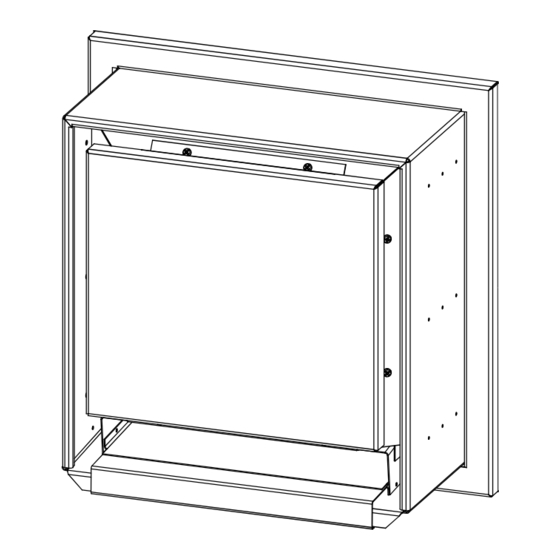
Page 18: Parts Diagram
Parts Diagram ITEM PART No. DESCRIPTION 80001902 FRONT GRILL COVER 80002217 INNER GRILL 80000553 BLOWER ASSEMBLY 1’ TO 25’ 80000554 BLOWER ASSEMBLY 25’ TO 110’ 80002024 BLOWER GASKET 80002216 MOUNTING FLANGE 80002059 FIRESTOP KIT Fig. #36 120324-20_TCVT.PV-D 100005216... - Page 19 120324-20_TCVT.PV-D 100005216...
- Page 20 © 2019 Copyright Pacific Energy Fireplace Products LTD Reproduction, adaptation, or translation without prior written permission is prohibited, except as allowed under the copyright laws. For Technical Support, please contact your retailer. www.townandcountryfireplaces.net 2975 Allenby Rd., Duncan, BC V9L 6V8 Printed in Canada...
Need help?
Do you have a question about the TC Series and is the answer not in the manual?
Questions and answers