Advertisement
Quick Links
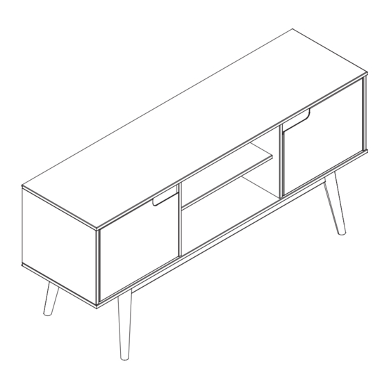
Item:
Please visit our website for the most current instructions, assembly tips, to report damage
or request parts. www.walkeredison.com
Copyright © 2018, by Walker Edison Furniture Co., LLC,
Copyright © 2018, by W
W58ADR2D
Assembly Instructions
alker Edison Furniture Co., LLC, All rights reserved.
Revised 08/2023-V8
All rights reserved.
P.1
Advertisement

Subscribe to Our Youtube Channel
Related Manuals for Walker Edison W58ADR2D


Summary of Contents for Walker Edison W58ADR2D
- Page 1 Please visit our website for the most current instructions, assembly tips, to report damage or request parts. www.walkeredison.com Revised 08/2023-V8 Copyright © 2018, by W Copyright © 2018, by Walker Edison Furniture Co., LLC, alker Edison Furniture Co., LLC, All rights reserved. All rights reserved.
- Page 2 and hammmer...
-
Page 3: Parts List
Parts List 19 19 Left side panel 01 pc 01 pcs Right center panel Left center panel 01 pc Base 01 pcs Back panel 01 pc Foot crossbeam 02 pcs Center shelf 01 pc Foot 04 pcs Side shelf 02 pcs Front / Back croosbeam 02 pcs 04 pcs... -
Page 4: Hardware List
Hardware List Ø8*30mm Wooden dowel 44 pcs Ø4*30mm Screw 28 pcs Screw 13 pcs Ø4*40mm Washer 02 pcs Ø3,5*25mm Screw 08 pcs Wall anchor 01 pc Ø4*16mm Screw 26 pcs 04 pcs Hing Screw Ø7*60mm 08 pcs Hex Key 01 pc Corner 02 pcs Ø10*10mm... - Page 5 Hardware List Ø6*35mm 01 pc Ø4*16mm Screw 01 pc Ø8mm Silicone 02 pcs Slap Hole 04 pcs Philips head screwdriver required Hammer recommended for assembly (not included) for assembly (not included) The hardware quantities listed above are required for proper assembly. Some extra hardware may also have been included.
- Page 6 Step 1 Ø8*30mm Insert wood dowel (A) into parts (4), (11) and (25). Insert support (N) into parts (4) and (25). Ø8*14mm Step 2 Ø8*30mm Insert wood dowel (A) into parts (2), (23), (27) and (29). Insert support (N) into parts (2) and (23). Ø8*14mm...
- Page 7 Step 3 Insert wood dowel (O) into parts (27) and (29). Ø6*30mm Step 4 Ø4*16mm Attach the accessory (R) to the accessory (L), then secure everything to the part (21) with a screw (H) and a Phillips screwdriver.
- Page 8 Step 5 Secure parts (4) and (25) to part (11). Step 6 Secure part (2), (4), (23) and (25) to part (21) with screw (B) and a Phillips screwdriver. Ø4*30mm Attach part (11) to parts (4) and (25) using screw (B) and a Phillips screwdriver.
- Page 9 Step 7 Attach the accessories (E) and (G) to the part (21) with a screw (Q) and a Phillips screwdriver. Ø4*16mm Step 8 Secure parts (28) to part (27). Step 9 Secure the assembled part to the part (26).
- Page 10 Step 10 Attach the assembled part to the base (26) using screw (B) and Phillips head screwdriver. Ø4*30mm Step 11 Secure parts (29) to parts (28). Use a object like a book to support part (29). Step 12 Attach the assembled part to the parts (29) and hold this parts while someone help to remove de objects (books).
- Page 11 Step 13 Attach the assembled part to the part (26) without disassemble. Step 14 Ø4*30mm Attach the assembled part to the base (26) using screw (B) and Phillips head screwdriver. P.11...
- Page 12 Step 15 Ø7*60mm Attach the foot (28) to the base (26) using screw (J) and hex key (K). Step 16 Attach part (26) to parts (2), (4), (23) and (25) using screw (C) and a Phillips screwdriver. Ø4*30mm Ø4*40mm Attach the part (29) to the base (26) using screw (B) and Phillips head screwdriver. P.12...
- Page 13 Step 17 Ø7*60mm Insert screw (J) into part (19) using a Hex Key (K). Step 18 Fix the parts (19) to the body using the screw (F) and Phillips screwdriver. Ø3,5*25mm P.13...
- Page 14 Step 19 Secure back panel (10) to body with nails (M) and hammer. Ø10*10mm Step 20 Insert the accessory (S) into the holes in the parts (2), (4), (23) and (25). Insert parts (15) to the body of the product. P.14...
- Page 15 Step 21 Ø4*16mm Attach the hardware (I) to the (32) and (33) parts with the screw (H) and a Phillips screwdriver. Step 22 Ø4,0*16mm Secure part (32), (33) to part (2) and (23) with screw (H). P.15...
- Page 16 Step 23 Ø4,0*16mm Attach screw (H). P.16...
- Page 17 Step 24 WARNING Serious or fatal crushing injuries can occur from tip-over. To help prevent tip-over, install tip restraints per instructions. If using to support a television or monitor: For use with televisions weighing 50lbs (22.67Kg) or less and no wider than this product. Use with heavier televisions may result in instability causing tip over resulting in death or serious injury.
Need help?
Do you have a question about the W58ADR2D and is the answer not in the manual?
Questions and answers